


1. Introduction
3D reconstruction technology is a cutting-edge research field currently widely used in AR, VR, surveying and mapping, cultural heritage reconstruction, medical imaging, high-precision mapping, game development, image entertainment, autonomous driving technology, and more. Internationally, 3D reconstruction research teams started earlier and have substantial technical accumulation. In contrast, China started late, has fewer practical results, and lacks core competitiveness. Currently, most popular 3D reconstruction software and tools in the Chinese market are developed abroad, with most of the market dominated by foreign companies such as Autodesk, Capturing Reality, Acute3D/Context Capture, PhotoModeler, and EDDA Technology (a subsidiary of EDDA USA). Structured light technology is one of the most widely used technologies in the field of industrial close-range 3D reconstruction, known for its high precision, insensitivity to weak textures, fast detection speed, and high resolution. One of the most common categories of structured light is stripe structured light, as shown below:
 style='position:absolute;left:0pt;margin-left:226.9pt;margin-top:222.1pt;height:0.1pt;width:0.05pt;mso-wrap-distance-bottom:0pt;mso-wrap-distance-top:0pt;z-index:251666432;mso-width-relative:page;mso-height-relative:page;' />style='position:absolute;left:0pt;margin-left:213.15pt;margin-top:220.45pt;height:0.15pt;width:0.2pt;mso-wrap-distance-bottom:0pt;mso-wrap-distance-top:0pt;z-index:251667456;mso-width-relative:page;mso-height-relative:page;' />
Figure 1. Stripe Structured Light
Currently, structured light 3D reconstruction technology often sacrifices time to improve accuracy. From a software perspective, reducing time means reducing the number of patterns needed for single-frame 3D reconstruction. Researchers have made significant efforts in this area. The research group led by Professors Qian Chen and Chao Zuo at Nanjing University of Science and Technology established the theoretical framework for stripe structured light phase shifting [1] and temporal phase unwrapping [2], proposing a series of composite encoding methods such as dual-frequency phase shifting [3], 2+2 step phase shifting [4], geometric constraint composite phase shifting [5], speckle composite Fourier method [6], and micro frequency shift Fourier transform method [7].
From an algorithmic perspective, current mature image processing technology, ISP, is not suitable for high-precision 3D reconstruction. ISP processing aims for aesthetic appeal and adaptation to human visual observation, which involves certain distortions and compressions of the image, detrimental to research-level 3D reconstruction. Therefore, this paper implements 3D reconstruction of structured light using traditional graphics methods, reconstructing a set of ISP images and RAW images, and evaluates the improvement in reconstruction accuracy using point cloud differences, demonstrating that using non-visual information as input can significantly enhance imaging accuracy.
2. Technologies Used
2.1. Stripe Structured Light
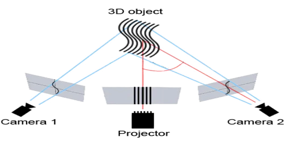
Structured light technology is one of the most widely used technologies in the field of industrial close-range 3D reconstruction due to its high precision and insensitivity to weak textures. One of the most common categories within structured light is stripe structured light, as shown below:
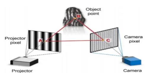
Figure 2. The measurement of stripe structured light
The measurement of stripe structured light mainly consists of a projector and a camera. Sine stripes are generated by computer programming, and the projector projects these sine stripes onto the object being measured. The camera captures the degree of bending of the stripes modulated by the object. By demodulating these bent stripes to obtain the phase and then using corresponding algorithms to process the phase, depth information can be calculated.
2.2. Multi-Step Phase Shifting Method
Wrapped phase \( \) refers to the phase directly obtained from the modulated sine stripes, with the interval between \( \) . Continuous phase is obtained by unwrapping the wrapped phase \( \) combined with the fringe order k.
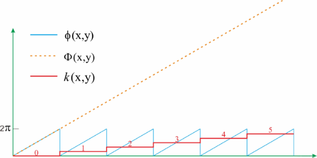
Figure 3. Phase Relationship Diagram
One method to obtain the wrapped phase is the multi-step phase shifting method. Taking the three-step phase shifting method as an example, the principle is as follows: In the phase shifting method, sinusoidal intensity modulated fringe patterns are projected sequentially onto the object surface. The deformed fringe distribution captured by the camera can be expressed as: \( {I_{n}}=A(x,y)+B(x,y)cos[ϕ(x,y)-2πn/3] \) ,where \( A(x,y) \) is the average intensity related to the background brightness and pattern brightness, \( B(x,y) \) is the modulation intensity related to pattern contrast and surface reflectivity, \( n \) is the phase shift order, \( ϕ(x,y) \) is the corresponding wrapped phase map. The wrapped phase can be solved using the following equations:
\( Φ(x,y)=ta{n^{-1}}\frac{\sum _{n=0}^{2}{I_{n}}(x,y)sin(2π /3)}{\sum _{n=0}^{2}{I_{n}}(x,y)cos(2π /3)} \)
2.3. Multi-Frequency Phase Unwrapping Method
Since the wrapped phase obtained above is not continuous, there can be phase ambiguities when finding corresponding points. Therefore, the multi-frequency temporal phase unwrapping method is used to unwrap the wrapped phase. Under structured light of different frequencies (taking two frequencies as an example), we obtain the following two equations:
\( {Φ_{h}}(x,y)={ϕ_{h}}(x,y)+2π{K_{h}}(x,y) \)
\( {Φ_{l}}(x,y)={ϕ_{l}}(x,y)+2π{K_{l}}(x,y) \)
where \( \) and \( \) are the integer parts of the fringe orders at low and high frequencies, respectively. The low-frequency phase \( \) is recovered using a unit frequency pattern, so no phase unwrapping is needed. Using the equation:
\( {k_{h}}(x,y)=Round[\frac{({λ_{l}}/{λ_{h}}){Φ_{l}}(x,y)-{ϕ_{h}}(x,y)}{2π}] \)
where Round[] denotes the rounding function. The dual-frequency method can be extended to multi-frequency methods. In this project, four frequencies are used.
2.4. Triangulation Method
The key to triangulation is finding corresponding points using epipolar constraints and unwrapped phase. This step is similar to stereo measurement. The projector is also treated as a camera in the stripe structured light method. We need to find the corresponding point for each point in the camera matrix in the projector matrix using the principle of epipolar constraint.
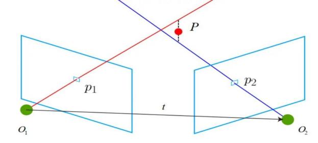
Figure 4. Triangulation Diagram
As shown, the epipolar constraint describes the constraint formed when the same point projects onto images from two different perspectives. With the known and system calibration parameters, the range of can be reduced to a line, the epipolar line. By finding the point on the epipolar line with the same unwrapped phase as , we obtain the corresponding point. With corresponding points, the depth information of point p can be calculated. Obtaining depth information requires world coordinates. Using corresponding points and camera parameters, a linear homogeneous equation system can be constructed:
\( {A_{x}}=0 A=[\begin{matrix}{P_{1x}}*K{1_{3}}-K{1_{1}} \\ {P_{1y}}*K{1_{3}}-K{1_{2}} \\ {P_{2x}}*K{2_{3}}-K{2_{1}} \\ {P_{2y}}*K{1_{3}}-K{2_{2}} \\ \end{matrix}] x=[\begin{matrix}{x_{w}} \\ {y_{w}} \\ {z_{w}} \\ w \\ \end{matrix}] \)
By performing singular value decomposition on A, the coordinates of each world point can be solved, thereby solving the depth map and point cloud.
3. Results and Analysis
3.1. Deployment on Handheld Devices for Testing
To verify the effectiveness of the proposed algorithm, we used TensorRT to deploy the neural network on a handheld device. The handheld device was used in real-world applications to test its reliability and identify any shortcomings.
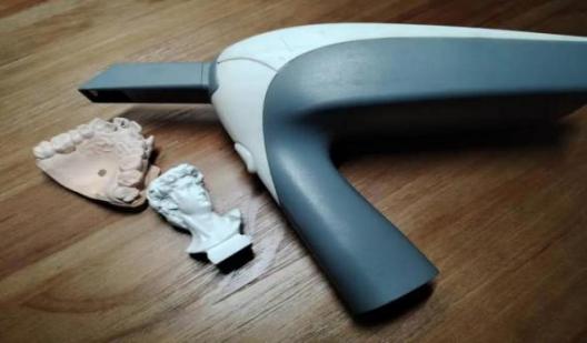
Figure 5. Handheld Device (The device used for this test is shown in this image)
3.2. Comparison and Analysis
3.2.1. Image Acquisition and Preprocessing

Figure 6. Example of Stripe Images from Group A
Figure 7. Example of Stripe Images from Group B
At this stage, the structured light projected by the equipment has a frequency of 64. The structured light projected by the equipment has a frequency of 64.
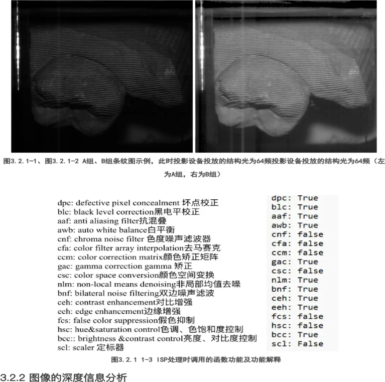
Figure 8. Functions Called During ISP Processing and Their Explanations
We selected the raw information and set this group of images as Group A. The images processed by ISP were set as Group B. We used traditional graphics methods to calculate the depth maps and point clouds of these groups of images and compared the two groups.
3.2.2. Depth Information Analysis of Images
Then, the phase of both groups of images was unwrapped to obtain the unwrapped phase matrix. Using MATLAB software, the phase maps were plotted (using the image() function), and it was initially observed that the accuracy of the information in the ISP-processed images was relatively lower.
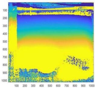
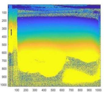
Figure 9. Unwrapped Phase Map of Group A
Figure 10. Unwrapped Phase Map of Group B
Next, the depth maps were further calculated for verification.
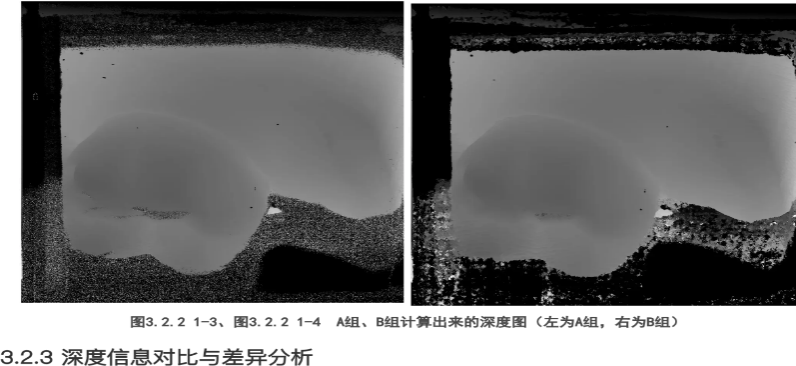
Figure 11. Calculated Depth Map of Group A
Figure 12. Calculated Depth Map of Group B
3.2.3. Comparison and Analysis of Depth Information Differences
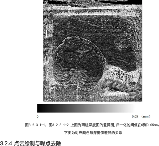
Figure 13. Difference Map of Depth Maps of Both Groups (Normalized values from 0 to 0.05mm). Lower Image: Corresponding Color and Depth Value Differences
Although differences can be observed from the depth maps, to clearly demonstrate the differences in depth values between the two groups, the depth maps were subtracted, and the differences were made absolute and normalized to obtain the difference map. This illustrates the impact of ISP processing on depth information.
3.2.4. Point Cloud Rendering and Noise Removal
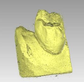
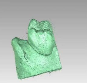
Figure 14. Point Cloud of Group A Rendered Using Geomagic Software
Figure 15. Point Cloud of Group B Rendered Using Geomagic Software
To eliminate noise interference and improve the credibility of the results, we further rendered the point clouds and removed most of the noise points.
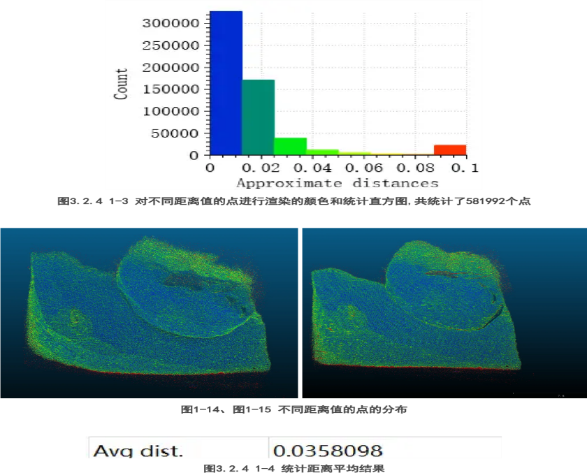
Figure 16. Color Rendering and Statistical Histogram of Points at Different Distance Values (Total of 581,992 points)

Figure 17. Distribution of Points at Different Distance Values
Figure 18. Statistical Results of Average Distance
Since a visual comparison of the point clouds alone could not clearly show the differences, we used CloudCompare software to load the two point clouds. Taking the point cloud of Group A as a reference, the distance from each point to the nearest point in Group B's point cloud was calculated. Based on the distance values, different colors were rendered, and the distances were statistically analyzed, as shown below. According to the point cloud comparison, it was found that most points with a distance greater than 0.1mm were noise points, so we only statistically analyzed points with distances from 0mm to 0.1mm.
3.2.5. Discussion of Results
Based on the statistical results and distribution view, it was found that the distance between the point clouds of Group A and Group B mostly ranged between 0~0.04mm, with an average value around 0.035mm. There was a significant discrepancy in the point cloud distribution, especially on steep surfaces of the object, indicating that the 3D reconstruction results of ISP-processed images and raw images differ significantly. A difference of 0.035mm constitutes a substantial precision loss in the field of close-range industrial 3D reconstruction. Therefore, the preliminary work can initially demonstrate that 3D reconstruction based on photon information has higher accuracy.
3.3. Further Analysis and Discussion
3.3.1. Effects of Enabling and Disabling Different ISP Algorithms
We further analyzed and discussed the significant image processing algorithms in ISP, such as bilateral noise filtering (BNF), edge enhancement (EEH), and non-local means denoising (NLM), while keeping other ISP algorithms disabled unless necessary. The statistical results are summarized in the table below:
Table 1. Impact of Different Algorithms on Results
bnf | eeh | nlm | Statistical Number of Points | Statistical Number of Points | Statistical Number of Points |
TRUE | TRUE | FALSE | 611320 | 0.03522 | 0.00672 |
TRUE | FALSE | TRUE | 603274 | 0.03163 | 0.00587 |
TRUE | TRUE | TRUE | 599513 | 0.03231 | 0.00578 |
TRUE | FALSE | FALSE | 607993 | 0.03113 | 0.00567 |
FALSE | TRUE | TRUE | 595211 | 0.03139 | 0.00538 |
FALSE | FALSE | TRUE | 598782 | 0.02949 | 0.00525 |
FALSE | TRUE | FALSE | 597596 | 0.02747 | 0.00397 |
FALSE | FALSE | FALSE | 594336 | 0.02631 | 0.00371 |
3.3.2. Results and Discussion
According to the statistical results, when the BNF, EEH, and NLM algorithms are all disabled, the mean deviation is minimal at 0.00371mm. In contrast, when certain ISP algorithms are enabled, the mean deviation increases significantly by 0.0002mm to 0.003mm compared to the state where BNF, EEH, and NLM algorithms are disabled, with error increments ranging from 7.01% to 81.13%.
We analyzed these specific ISP algorithms. The BNF algorithm (Bilateral Noise Filter) effectively filters out random Gaussian noise in images but also smooths edge information, resulting in image blurring, which is a key reason for the accuracy degradation caused by the BNF algorithm. The EEH algorithm (Edge Enhancement) highlights certain information in the original image while weakening other information, enhancing image contrast. However, this algorithm introduces significant interference in depth map calculations for 3D imaging. Finally, the NLM algorithm (Non-Local Means Denoising) searches for similar regions in the image on a block-by-block basis and averages these regions, effectively removing Gaussian noise but causing some loss of image information accuracy and leading to a degree of result distortion.
4. Conclusion
This study built code implementations for 3D reconstruction graphics using traditional computer graphics methods. It analyzed the 3D reconstruction of dental models by comparing depth maps and point clouds generated from non-visual information input (RAW images) and ISP-processed image information input, verifying that using non-visual information as input can enhance the accuracy of structured light 3D reconstruction. This technology also addresses the need for fast, high-precision 3D reconstruction across various fields. It can employ artificial intelligence techniques to learn the feature distribution of modulated light fields from photon images, reduce information loss caused by image signal processing, and, combined with differentiable point cloud rendering techniques, achieve 3D morphology reconstruction of objects from single-frequency structured light photon images. The research results, integrated with laboratory hardware systems, form an applicable handheld 3D imaging system.
Acknowledgement
Liyang Wan and Xi Chu: Code writing, conceptualization, methodology, data management, writing, draft preparation, visualization, equipment provision.
References
[1]. Zuo, C. et al. Phase shifting algorithms for fringe projection profilometry: A review. Opt. Lasers Eng. 109, 23–59 (2018).
[2]. Zuo, C., Huang, L., Zhang, M., Chen, Q. & Asundi, A. Temporal phase unwrapping algorithms for fringe projection profilometry: A comparative review. Opt. Lasers Eng. 85, 84–103 (2016).
[3]. Zuo, C. et al. High-speed three-dimensional shape measurement for dynamic scenes using bi-frequency tripolar pulse-width-modulation fringe projection. Opt. Lasers Eng. 51, 953–960 (2013).
[4]. Zuo, C., Chen, Q., Gu, G., Feng, S. & Feng, F. High-speed three-dimensional profilometry for multiple objects with complex shapes. Opt. Express 20, 19493–19510 (2021).
[5]. Tao, T. et al. Real-time 3-D shape measurement with composite phase-shifting fringes and multi-view system. Opt. Express 24, 20253–20269 (2016).
[6]. Feng, S., Chen, Q. and Zuo, C. Graphics processing unit–assisted real-time three-dimensional measurement using speckle-embedded fringe. Applied optics 54(22), 6865-6873 (2015).
Cite this article
Wan,L.;Chu,X. (2024). Study on the impact of camera ISP algorithms on stripe structured light 3D reconstruction and the improvement of 3D reconstruction accuracy by photon input. Applied and Computational Engineering,88,20-28.
Data availability
The datasets used and/or analyzed during the current study will be available from the authors upon reasonable request.
Disclaimer/Publisher's Note
The statements, opinions and data contained in all publications are solely those of the individual author(s) and contributor(s) and not of EWA Publishing and/or the editor(s). EWA Publishing and/or the editor(s) disclaim responsibility for any injury to people or property resulting from any ideas, methods, instructions or products referred to in the content.
About volume
Volume title: Proceedings of the 6th International Conference on Computing and Data Science
© 2024 by the author(s). Licensee EWA Publishing, Oxford, UK. This article is an open access article distributed under the terms and
conditions of the Creative Commons Attribution (CC BY) license. Authors who
publish this series agree to the following terms:
1. Authors retain copyright and grant the series right of first publication with the work simultaneously licensed under a Creative Commons
Attribution License that allows others to share the work with an acknowledgment of the work's authorship and initial publication in this
series.
2. Authors are able to enter into separate, additional contractual arrangements for the non-exclusive distribution of the series's published
version of the work (e.g., post it to an institutional repository or publish it in a book), with an acknowledgment of its initial
publication in this series.
3. Authors are permitted and encouraged to post their work online (e.g., in institutional repositories or on their website) prior to and
during the submission process, as it can lead to productive exchanges, as well as earlier and greater citation of published work (See
Open access policy for details).
References
[1]. Zuo, C. et al. Phase shifting algorithms for fringe projection profilometry: A review. Opt. Lasers Eng. 109, 23–59 (2018).
[2]. Zuo, C., Huang, L., Zhang, M., Chen, Q. & Asundi, A. Temporal phase unwrapping algorithms for fringe projection profilometry: A comparative review. Opt. Lasers Eng. 85, 84–103 (2016).
[3]. Zuo, C. et al. High-speed three-dimensional shape measurement for dynamic scenes using bi-frequency tripolar pulse-width-modulation fringe projection. Opt. Lasers Eng. 51, 953–960 (2013).
[4]. Zuo, C., Chen, Q., Gu, G., Feng, S. & Feng, F. High-speed three-dimensional profilometry for multiple objects with complex shapes. Opt. Express 20, 19493–19510 (2021).
[5]. Tao, T. et al. Real-time 3-D shape measurement with composite phase-shifting fringes and multi-view system. Opt. Express 24, 20253–20269 (2016).
[6]. Feng, S., Chen, Q. and Zuo, C. Graphics processing unit–assisted real-time three-dimensional measurement using speckle-embedded fringe. Applied optics 54(22), 6865-6873 (2015).