


1. Introduction
To solve the deteriorating global environment and insufficient energy reserves, renewable energy sources such as solar power are gaining prominence as primary alternatives [1-2]. A photovoltaic (PV) array can output its maximum power under special temperature and solar irradiance conditions at a particular voltage. By using the impedance matching principle in the equivalent model of the PV array, this voltage point can be calculated and tracked. The process of tracking this maximum power point (MPP) using power electronic technologies [3] is referred to as maximum power point tracking (MPPT).
Traditional MPPT algorithms include three main methods: the Perturb and Observe method (PO), the Incremental Conductance method (INC), and the Constant Voltage method (CV). At the beginning, literatures [4-7] compared the output characteristics of these above-mentioned methods and proposed an improved PO algorithm aimed at the false trips in the PO method. However, in scenes such as partial shading of PV panels, traditional algorithms often fail to track effectively. Consequently, replacing traditional MPPT algorithms with intelligent algorithms has become a research trend. To solve the multi-peak output problem caused by partial shading, literatures [8-11] proposed the Particle Swarm Optimization (PSO) algorithm. This algorithm effectively resolves the challenges of multi-peak output tracking and local optimum under partial shading conditions. However, it still faces issues such as parameter adaptability. Literatures [12-15] introduced the Fuzzy Logic Control method, but this method heavily depends on the designer’s expertise and intuition. Moreover, insufficient training data can lead to poor model performance. In summary, current MPPT research faces the following challenges:1) Limited robustness of MPPT algorithms.2) Significant power output oscillation amplitudes.
To solve these challenges, this paper proposes an MPPT control algorithm based on an improved Crow Search Algorithm (CSA). Using a PV array integrated with a boost circuit topology under partial shading conditions, this study conducts simulations in MATLAB/Simulink. The proposed method is compared with the traditional PO method under varying solar irradiance and temperature conditions in partial shading scenes. The proposed approach offers the following innovations:
1) The traditional CSA algorithm is enhanced with an auto judgment of power output to avoid local optimum.
2) Based on the first improvement, an enhanced CSA algorithm incorporating elite individuals replaces the traditional CSA algorithm, effectively reducing the amplitude of power output oscillations.
The structure of this paper is as follows: Section II represents the modeling of the PV system and introduction of the integrated circuit. The principles of traditional PO tracking, the traditional CSA algorithm, and the improved CSA algorithm are revealed in Section II. Section IV shows simulation in MATLAB/Simulink and analysis.
2. System Modeling and Circuit Integration
2.1. Photovoltaic System Modeling
Solar cells are the fundamental components of solar photovoltaic systems. Their I-U and P-U characteristics are influenced by solar irradiance, ambient temperature, and the parameters of the PN junction in the solar cells, exhibiting a nonlinear relationship [16]. Based on these characteristics, an equivalent circuit model of solar cells can be established. Commonly used equivalent circuit models include the single-diode model and the dual-diode model. The single-diode model is widely used because it accurately reflects the working principles of solar cells with a simple circuit topology. The circuit diagram of the single-diode model is shown in Figure 1.
 ,
,
Figure 1: Single diode equivalent model of solar cell
where the photocurrent \( {I_{ph}} \) generated by the solar cell is represented as a current source with an equivalent current value. The PN junction in the solar cell is represented by a parallel diode, while losses due to the material properties of the solar cell are represented by a series resistance \( {R_{s}} \) and a paralleled one \( {R_{sh}} \) . According to Kirchhoff's current law, the following equation can be derived from the circuit in Figure 1:
\( I={I_{ph}}-{I_{d}}-{I_{sh}} \) (1-1).
The characteristic equation of the solar cell can be obtained as Equation(1-2)[17]:
\( I={I_{ph}}-{I_{0}}\cdot ({e^{(q\cdot (U+I\cdot {R_{s}})/(A\cdot K\cdot T))}}-1)-\frac{I\cdot {R_{s}}+U}{{R_{sh}}} \) (1-2),
where \( {I_{0}} \) is the reverse saturation current of the diode, \( q \) is the elementary charge, \( {R_{s}} \) is the series resistance, \( A \) is the ideality factor of the PN junction, \( K \) is Boltzmann’s constant, and \( T \) is the absolute temperature in Kelvin.
Since Equation (1-2) is transcendental and complex to solve, it needs to be properly simplified. The order of magnitude of \( {R_{sh}} \) is typically 103 times larger than \( {R_{s}} \) , allowing \( \frac{I\cdot {R_{s}}+U}{{R_{sh}}} \) to be ignored. The forward current of the diode is approximately zero due to manufacturing processes, making \( {I_{ph}} \) approximately equal to the short-circuit current \( {I_{sc}} \) of the circuit shown in Figure 1. Hence, Equation (1-2) can be simplified as:
\( ={I_{sc}}\cdot [1-{C_{1}}\cdot ({e^{\frac{V}{{C_{2}}\cdot {V_{oc}}}}}-1)] \) (1-3),
where \( {V_{oc}} \) is the open-circuit voltage, \( {C_{1}}=\frac{{I_{0}}}{{I_{sc}}},{C_{2}}=\frac{AKT}{Q} \) .
At MPP, substituting the voltage \( {V_{m}} \) and current \( {I_{m}} \) into Equation (1-3) yields:
\( {I_{m}}={I_{sc}}\cdot [1-{C_{1}}\cdot ({e^{\frac{{V_{m}}}{{C_{2}}\cdot {V_{oc}}}}}-1)] \) (1-4),
Assuming \( {e^{\frac{V}{{C_{2}}\cdot {V_{oc}}}}} \) ≫1, Equation (1-4) can be further simplified to:
\( {C_{1}}=(1-\frac{{I_{m}}}{{I_{sc}}})\cdot {e^{\frac{{V_{m}}}{{C_{2}}\cdot {V_{oc}}}}} \) (1-5),
By substituting the open-circuit state \( I=0,U={V_{oc}} \) ,Equation (1-5) becomes:
\( ={I_{sc}}\cdot [1-(1-\frac{{I_{m}}}{{I_{sc}}})\cdot {e^{\frac{-{V_{m}}}{{C_{2}}\cdot {V_{oc}}}}}\cdot ({e^{\frac{1}{{C_{2}}}}}-1)] \) (1-6),
Assuming \( {e^{\frac{1}{{C_{2}}}}} \) ≫1, the equation is further simplified to:
\( {C_{2}}=(\frac{{V_{m}}}{{V_{oc}}}-1){[ln(1-\frac{{I_{m}}}{{I_{sc}}})]^{-1}} \) (1-7).
Solar cell manufacturers typically provide the maximum power point voltage \( {V_{m\_ref}} \) and current \( {I_{m\_ref}} \) measured under standard test conditions (STC), i.e., standard temperature ( \( {T_{ref}}=25°C \) ) and standard irradiance ( \( {S_{ref}}=1000W/{m^{2}} \) ). Variations in temperature and solar irradiance affect photon generation in solar cells, necessitating corrections to \( {I_{m}},{I_{sc}},{V_{m}},{V_{oc}} \) using Equations (1-8) to (1-13):
\( ΔT=T-{T_{ref}} \) (1-8),
\( ΔS=\frac{S}{{S_{ref}}}-1 \) (1-9),
\( {I_{sc}}={I_{sc\_ref}}\cdot \frac{S}{{S_{ref}}}\cdot (1+αΔT) \) (1-10),
\( {V_{oc}}={V_{oc\_ref}}\cdot (1-γΔT)\cdot ln(e+βΔS) \) (1-11),
\( {I_{m}}={I_{m\_ref}}\cdot \frac{S}{{S_{ref}}}\cdot (1+αΔT) \) (1-12),
\( {V_{m}}={V_{m\_ref}}\cdot (1-γΔT)\cdot ln(e+βΔS) \) (1-13),
where \( α、β、γ \) are all constants, commonly taking values as \( α=0.0025,β=0.5,γ=0.00288 \) .
2.2. Output Characteristics of PV Systems under Partial Shading [24]
Using two identical PV modules connected in series as an example, the single-diode equivalent model established above is used for analysis. Under partial shading, various levels of irradiance on the PV modules result in varying short-circuit currents \( {I_{sc}} \) . When the output current of the PV array lies between the short-circuit currents of the two modules, the diode in the module with the lower \( {I_{sc}} \) conducts, and the output characteristic is determined by the module with the higher \( {I_{sc}} \) . When the output current is insufficient to activate the diode of the module with the lower \( {I_{sc}} \) , the output characteristic of the PV array equals the combined output characteristics of both modules.
When the PV array consists of multiple series-connected modules, the analysis process remains the same. This paper studies a PV array consisting of three identical modules in series. The parameters for each module are as follows:
Table 1: Essential parameters of PV module
Parameter Value Unit |
Open-circuit voltage \( {V_{oc}} \) 21.7 \( V \) Voltage at MPP \( {V_{m}} \) 15 \( V \) Short-circuit current \( {I_{sc}} \) 4.8 \( A \) Current at MPP \( {I_{m}} \) 3.7 \( A \) Maximum power \( {P_{m}} \) 55.5 \( W \) |
2.3. Boost Converter Circuit [18]
 ,
,
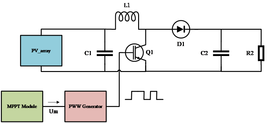
Figure 2: Boost circuit boarded with MPPT module.
where \( {C_{1}} \) is the filtering capacitor that stabilizes the output voltage. The IGBT switch \( {Q_{1}} \) , controlled appropriately, works with the diode \( {D_{1}} \) to allow the inductor \( { L_{1}} \) to absorb and release energy. When \( {Q_{1}} \) conducts, current flows through \( L \) , storing energy from the input voltage, while the load is powered by \( {C_{1}} \) .When \( {Q_{1}} \) is off, \( L \) releases the stored energy, powering the load with energy from both \( {C_{1}} \) and \( L \) . A sufficiently large inductor ensures continuous current operation in the boost circuit. By adjusting the duty cycle of \( {Q_{1}} \) , the output voltage can be controlled to exceed the input voltage, achieving voltage boosting.
3. MPPT Algorithms
3.1. PO Method [4]
The principle of the PO method is as follows: a small perturbation is applied to the PV system, and the change in output power before and after the perturbation is observed. If the output power increases, it indicates that the current voltage is less than \( { V_{mpp}} \) , and the output voltage needs to be increased; otherwise, the output voltage should be decreased. To avoid misjudgment, the difference in power \( dP \) and the difference in voltage \( dV \) before and after the perturbation ( \( \frac{dP}{dV} \) ) are introduced for evaluation.
The relationship between the signs of \( dP \) , \( dV \) , and whether the output voltage should be increased is discussed as following false code:
Algorithm 1: the PO voltage adjustment |
1. if dP < 0 then 2. if dV < 0 then 3. Output: "Increase Output Voltage" 4. else if dV > 0 then 5. Output: "Decrease Output Voltage" 6. else if dP > 0 then 7. if dV > 0 then 8. Output: "Increase Output Voltage" 9. else if dV < 0 then 10. Output: "Decrease Output Voltage" 11. End |
3.2. CSA
CSA is an intelligent optimization algorithm proposed in 2016 by Askarzadeh et al., inspired by the natural foraging behavior of crows. Crows have the habit of storing excess food and, to obtain more food, they follow other crows that have found food, discovered their storage locations, and steal the food. If a crow detects that it is being followed, it will randomly fly to confuse its pursuers.
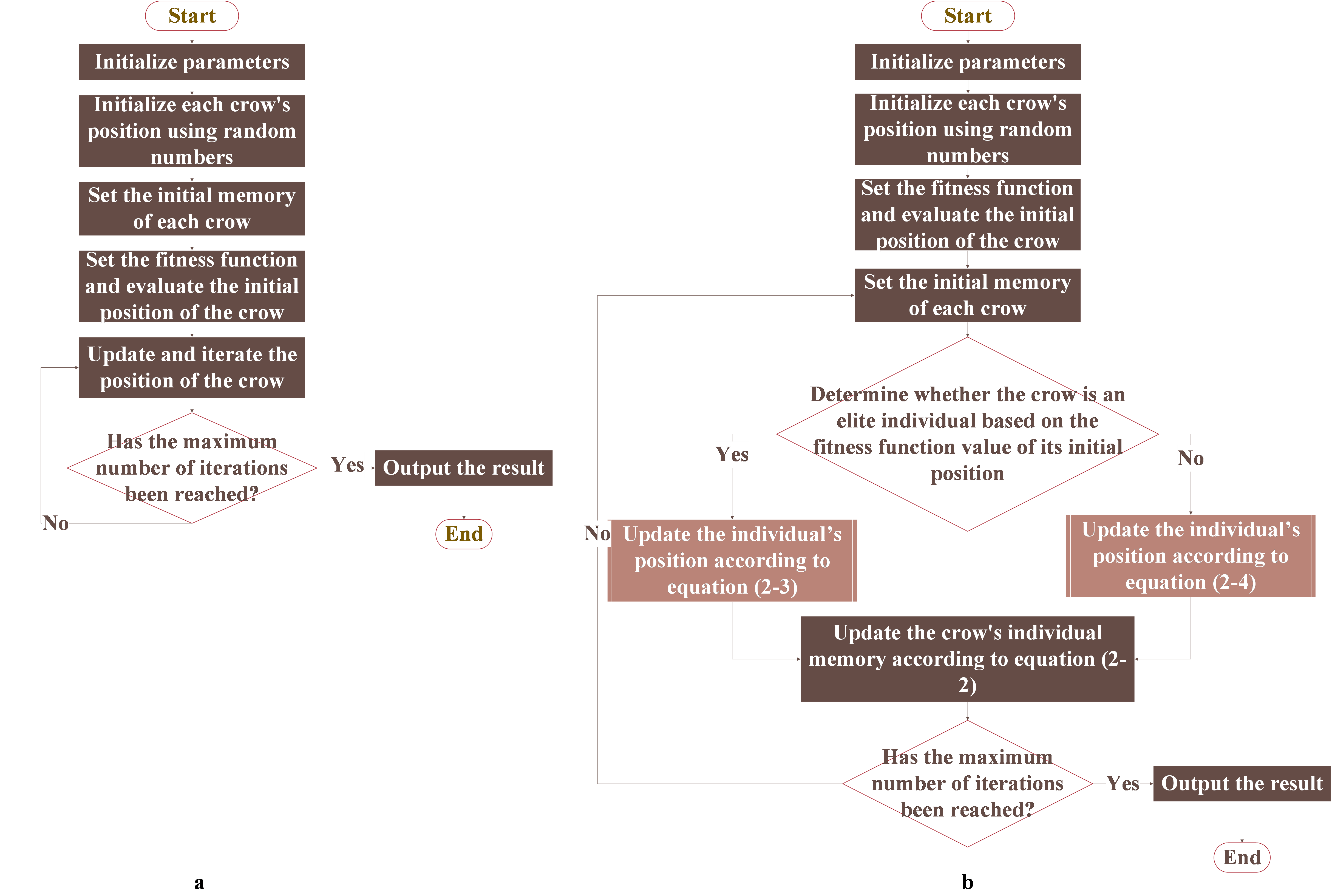
Figure 3: The compared processes of CSA(a) and Improved CSA(IMCSA)(b)
The parameters that need to be initialized include the size of the crow population \( N \) , the maximum number of iterations, the flight length \( fl \) , and the awareness probability \( AP \) . The fitness function \( f(x) \) should be designed according to specific requirements, and its value evaluates the quality of a crow’s position: the higher the fitness function value, the better the crow’s current position; conversely, a lower value indicates a worse position.
Subsequently, the algorithm randomly generates the initial positions \( {x_{i}}(t) \) of the crows and their memory of the best positions \( {m_{i}}(t) \) , representing the locations of stored food. During the iterative process of the algorithm, an individual crow randomly selects another crow as its tracking target, with the probability of being discovered set to \( AP \) . If crow a is discovered by crow \( b \) during tracking, \( a \) will randomly choose a new flight destination. Otherwise, a will attempt to approach b’s stored food location. This process can be expressed by Equation (3-1).
\( {x_{i}}=\begin{cases} \begin{array}{c} {x_{i}}+{r_{1}}∙fl∙({m_{i}}(t)-{x_{i}}(t)) { r_{2}}≥AP \\ random otherwise \end{array} \end{cases} \) (3-1)
At the end of each iteration, the positions of the crows are re-evaluated using the fitness function. These are then compared with the best positions stored in their memory. If the current position is better than the memorized best position, the crow's memory is updated accordingly. This process can be expressed by Equation (3-2).
\( {m_{i}}(t+1)=\begin{cases} \begin{array}{c} {x_{i}}(t+1) f({x_{i}}(t+1)) \lt f({m_{i}}(t)) \\ {m_{i}}(t) otherwise \end{array} \end{cases} \) (3-2)
Until the iteration times reached its upper limit, the algorithm outputs its result.
3.3. Optimization-Oriented Crow Search Algorithm Guided by Elite Individuals
Based on the above characteristics, reference [20] proposes an optimization strategy that establishes elite individuals according to the amount of stored food and uses their memorized positions as guidance. In this strategy, the top s crows with the highest stored food quantities are designated as elite individuals, while the remaining \( N-s \) crows are classified as ordinary individuals. At time \( t \) , the amount of food stored by crow \( k \) is represented by the fitness value of its storage location.
To prevent their food from being stolen, elite individuals usually operate near their nests and do not attempt to steal from others. Based on this behavior, the position of elite individuals can be determined using Equation (3-3).
\( {x_{i,j}}(t+1)=\begin{cases} \begin{array}{c} {m_{i,j}}(t)+(2{r_{1}}-1)×({m_{i,j}}(t)-1) {r_{2}} \\ {m_{i,j}}(t)+(2{r_{1}}-1)×{m_{i,j}}(t) otherwise \end{array} \end{cases} \) (3-3)
where \( j=1,2,...D \) ,while \( D \) represents the dimensionality of the search space, and \( {r_{1}},{r_{2}} \) are random numbers within the interval [0,1].
The behavior of ordinary individuals remains consistent with that of crows prior to the improvement. Their positions can be determined using the improved version of Equation (3-2), which is represented as Equation (3-4).
\( {x_{i,j}}(t+1)=\begin{cases} \begin{array}{c} {x_{i,j}}(t)+{r_{1}}∙fl(t)∙({m_{k,j}}(t)-{x_{i,j}}(t)) {r_{2}} \gt AP \\ random otherwise \end{array} \end{cases} \) (3-4)
where \( {m_{k}}(t)=[{m_{k,1}}(t)...{m_{k,D}}(t)] \) represents the food storage nest of elite individual \( k \) , and individual \( k \) is randomly selected from the elite individuals. \( {r_{1}},{r_{2}} \) are random numbers within the interval [0,1]. \( fl(t)=0.5\cdot exp{(1-\frac{t}{T})^{2}} \) is the flight step size function of crow \( i \) . \( t \) is the search time variable. \( T \) is the upper limit of the search time.
3.4. Application of the Improved Crow Search Algorithm in MPPT
The improved CSA is applied to PV MPPT. In the algorithm, each crow individual represents the output voltage of the current photovoltaic system, with each individual tasked with finding the maximum power point voltage \( { V_{m}} \) . The final output result will be the maximum power point voltage \( { V_{m}} \) .The crow’s flight step size corresponds to the voltage increment generated during each iteration of the MPPT process. The dimensionality of the search space corresponds to the number of variables that need to be optimized by the algorithm. In this study, since the output voltage and output current of the PV system need to be optimized, the dimensionality is set to 2. To ensure that the voltage and current stay within a limited range, a condition is introduced: if the output power corresponding to a particular individual’s voltage exceeds 100W, the position of that individual is no longer updated. Additionally, 30 new individuals are generated at the last maximum power point of that individual. These new individuals update their velocity according to the two-dimensional particle swarm velocity formula (Equation 3-5). Here, \( v \) represents the velocity of the individual, \( w \) is the inertia weight, \( c \) is the learning factor, \( best \) is the individual’s best position, and \( {r_{3}} \) is a random number used to expand the search space. This modified algorithm will be referred to as the IMCSA algorithm.
\( v=w\cdot v+c\cdot {r_{3}}(u\_array(best)-x) \) (Equation 3-5).
The steps of applying IMCSA to MPPT are as follows:
Step 1: Initialize the parameters and design the fitness function \( f(x) \) with boundaries.
Step 2: Generate the initial positions of \( N \) crow individuals randomly within the two-dimensional search space using random numbers from the interval [0,1].
Step 3: Calculate the fitness values according to \( f(x) \) for each initial position and select the top \( s \) crows with the highest fitness values as elite individuals.
Step 4: Begin tracking the photovoltaic system's maximum power point. Elite individuals update their positions according to Equation (3-3), while ordinary individuals update their positions according to Equation (3-4).
Step 5: Update the memory of the crow individuals, i.e., the food storage positions, based on Equation (2-2).
Step 6: Check if the maximum number of iterations has been reached. If yes, terminate the iteration and output the result. If no, return to Step 4.
4. Simulation and Analysis
A model for photovoltaic array MPPT control was established in MATLAB/Simulink [21]. The simulation time is set to 6 seconds, with a system sampling period of 1e-05 seconds. The solver algorithm is automatically selected from variable step-size algorithms. The simulation circuit diagram is shown in Figure 5, and the parameters of the circuit components are listed in Table 3.
Table 3: Parameters of the simulation circuit components
Component Value Unit |
\( {C_{1}} \) 470e-6 \( F \) \( {C_{2}} \) 47e-6 \( F \) \( {R_{1}} \) 50 \( Ω \) \( {L_{1}} \) 1.2e-3 \( L \) |
Three series-connected photovoltaic modules were used, with solar irradiance values of 1000 W/m², 800 W/m², and 600 W/m² applied to simulate partial shading conditions. The temperature of all three photovoltaic modules was maintained at 25°C. Under these partial shading conditions, 50 simulation experiments were conducted for the PO, CSA MPPT, and IMCSA MPPT algorithms. In each experiment, the initial duty cycle of the three methods was set to 0.5. For both the CSA and IMCSA algorithms, the number of crow individuals (particles) was 50, and the maximum number of iterations was 30.
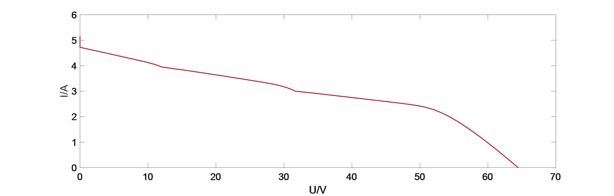
Figure 4: The current-voltage curve of PV _ array
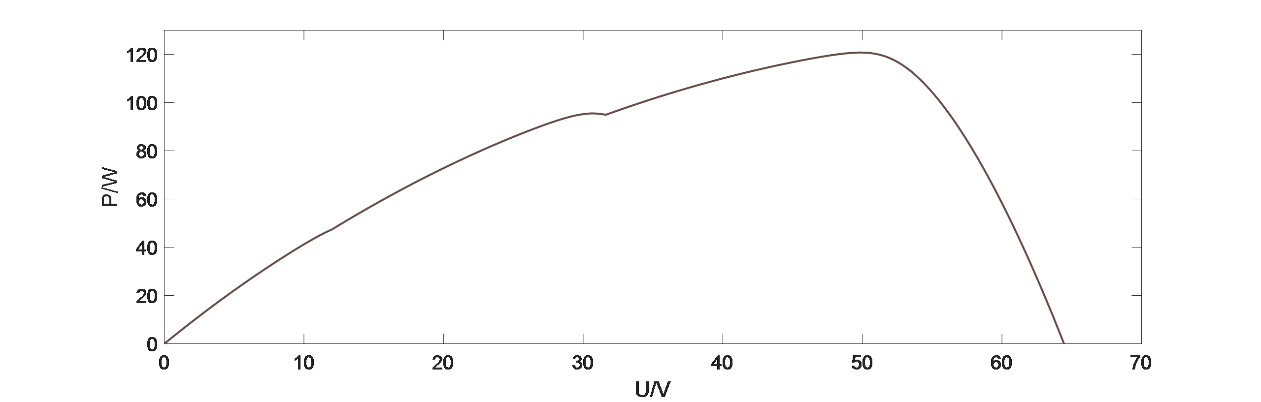
Figure 5: The power-voltage curve of PV _ array
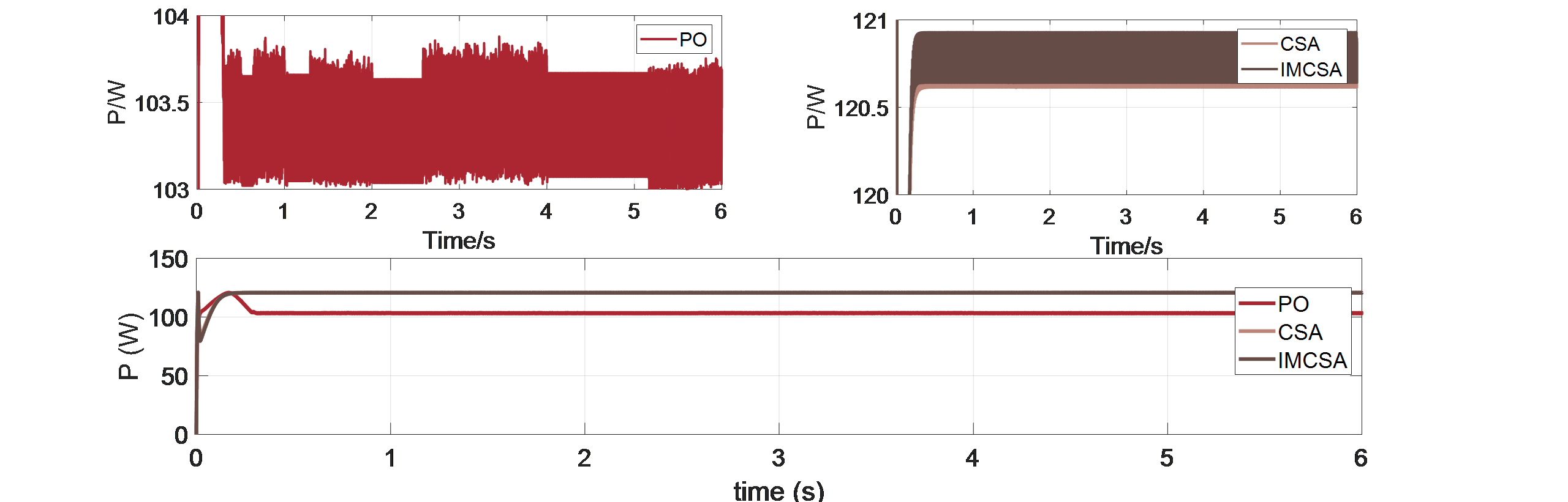
Figure 6: Overall comparison of output power for PO, CSA, and IMCSA algorithms and local comparison between CSA and IMCSA algorithms
Figure 6 shows the simulation results of the PO, CSA, and IMCSA algorithms. The results are presented sequentially from left to right and top to bottom, displaying output power, duty cycle, output voltage, and output current. From the results, it can be observed that under this partial shading condition: The PO algorithm stabilizes the output power waveform of the photovoltaic array at 0.45s, the CSA algorithm stabilizes at 0.19s, and the IMCSA algorithm stabilizes at 0.22s.
In terms of output power: The output power value of the PO algorithm is 103,431W the CSA is 120.753W, and the IMCSA is 120.791W.
Thus, the CSA and IMCSA algorithms significantly outperform the PO algorithm in this aspect, with an improvement of 16.46% and 16.78%.
In terms of output power oscillation amplitude: The oscillation amplitude of the PO algorithm is 0.744W, the oscillation amplitude of the CSA algorithm is 0.293W, and the oscillation amplitude of the IMCSA algorithm is 0.250W.
The IMCSA algorithm achieves reductions in oscillation amplitude of 17.20% compared to the CSA algorithm and 153.92% compared to the PO algorithm.
In summary [23], the proposed IMCSA algorithm achieves optimal fitness values, with the smallest oscillation amplitude and minimal power tracking loss. This enhances the stability and accuracy of MPPT, optimizing photovoltaic power generation efficiency.
5. Conclusion
Under variable solar irradiance conditions, photovoltaic cell output P-U curves exhibit large oscillation amplitudes and other issues. Traditional MPPT algorithms have slow tracking speeds and low tracking accuracy. This paper proposes an improved crow search algorithm (CSA), which leverages the guiding effect of elite individuals to enhance the motion strategy of crow populations. The output voltage, current, and power of the traditional PO, CSA, and the improved ADCSA algorithms were compared.
Simulation results demonstrate that under variable solar irradiance conditions, the improved ADCSA algorithm achieves faster maximum power point tracking with smaller oscillation amplitudes compared to the other two algorithms. This highlights the robustness of the proposed algorithm in adapting to environmental changes. Thus, the improved ADCSA algorithm is more adaptive, responsive, accurate, and stable under varying solar irradiance conditions, significantly improving power generation efficiency.
References
[1]. Ding M, Wang W, Wang X, et al. A review on the effect of large-scale PV generation on power systems[J]. Proceedings of the CSEE, 2014, 34(1): 1-14.
[2]. Yuyi F,Yifan Z,Muchen D, et al. Research on temperature distribution and power prediction model of photovoltaic modules [J/OL]. ACTA ENERGIAE SOLARIS
[3]. Yishu Z, Xiaowen W. Application of improved particle swarm optimization algorithm in multi-peak MPPT for photovoltaic array[J]. Distributed Energy Resources, 2018, 3(1): 34-38.
[4]. Yan C, Binghuang C, Dayong L. Comparative studies on the MPPT control algorithms of solar energy photovoltaic system[J]. ACTA ENERGIAE SOLARIS, 2006, 27(6): 535.
[5]. Zhang C. Research on MPPT and anti-islanding of grid-connected photovoltaic power generation system[D]. Zhejiang University, 2006: 28-29.
[6]. Yuansheng X. Research on control problems of solar photovoltaic generation system[D]. Zhejiang: Zhejiang university of technology.
[7]. Xuemei Y. The Research on Optimization Control of Solar Photovoltaic Application Systems [D].Shandong:Qingdao University,2009
[8]. Zhu Y, Shi X, Dan Y, et al. Application of PSO algorithm in global MPPT for PV array[C]Zhongguo Dianji Gongcheng Xuebao (Proceedings of the Chinese Society of Electrical Engineering). Chinese Society for Electrical Engineering, 2012, 32(4): 42-48.
[9]. Wu H, Sun Y, Meng C. Application of fuzzy controller with particle swarm optimization algorithm to maximum power point tracking of photovoltaic generation system[C]Proceedings of the CSEE. 2011, 31(6): 52-57.
[10]. Yanli L, Zhou H, Cheng Z. MPPT control method of PV System Based on PSO [J]. Computer Engineering,2010,36(05)
[11]. Xiaoling Y, Chen Y. Applications of Adaptive Particle Swarm Optimization Algorithm to MPPT of Shadow Photovoltaic Power Generation [J]. Electric Power,2013,46, (10)
[12]. Wu D, Wang X. A photovoltaic MPPT fuzzy controlling algorithm[J]. ACTA ENERGIAE SOLARIS, 2011, 32(6): 808-813.
[13]. Li X, Shi Q, Jiang Q. Application of double fuzzy control in MPPT of grid-connected photovoltaic generation system[J]. Electric Power Automation Equipment, 2012, 32(8): 113-117.
[14]. Xue Y,Wang S. Fuzzy control based on P&O applied in photovoltaic maximum power tracking [J]. ACTA ENERGIAE SOLARIS,2014,35,(09)
[15]. Fan Q, Yan F, Zhang C, et al. PV MPPT algorithm improvement based on fuzzy control[J]. ACTA ENERGIAE SOLARIS, 2017, 38(8): 2151-2158.
[16]. Zhou D, Zhao Z, Wu L. Analysis characteristics of photovoltaic arrays using simulation[J]. JOURNAL-TSINGHUA UNIVERSITY, 2007, 47(7): 1109.
[17]. Zongkui X. Research on power tracking and cooperative control for photovoltaic DC microgrid system [D].Hebei:Yanshan University,2023
[18]. Yu H. Research on DC/DC Converter of optical storage DC microgrid [D].Inner Mongolia : Inner Mongolia University of Science and Technology , 2023
[19]. Wang Y,Cao J, Zhiyang Q. A novel feature selection algorithm based on Crow Search Algorithm [J].Journal of Jilin University(Science Edition).2019,57(04):870
[20]. ZHANG Ning. Analyses and application research of Crow Search Algorithm and Dwarf Mongoose Optimization Algorithm [D].Guangxi:Guangxi Minzu University,2023
[21]. Yaodan C, Chen B ,Hongwei X ,Zhao Y, Li T . Application of improved particle swarm optimization in photovoltaic MPPT [J]. Chinese Journal of Power Sources.2022 ,46 (04)
[22]. Lianbing L ,Lanchao W ,Zhu L, Qiqi H, Shaobo Y. Application of adaptive immune particle swarm optimization in photovoltaic MPPT [J]. Chinese Journal of Power Sources. 2024 ,48 (04)
[23]. Wanyang W, Liying Z, Zhang M , Wenjia Z , Qiaoling T. Research on chimpanzee algorithm optimization of photovoltaic MPPT [J]. Chinese Journal of Power Sources .2024 ,48 (03)
[24]. Hewei L, Guanglin L, Pengyu C,Li K. Application of improved particle swarm optimization in multi-peak MPPT for photovoltaic arrays [J]. Automation & Instrumentation,2015,(03)
Cite this article
Lin,R. (2025). Application of Improved Crow Search Algorithm in MPPT of Photovoltaic Arrays under Partial Shading Conditions. Applied and Computational Engineering,142,47-56.
Data availability
The datasets used and/or analyzed during the current study will be available from the authors upon reasonable request.
Disclaimer/Publisher's Note
The statements, opinions and data contained in all publications are solely those of the individual author(s) and contributor(s) and not of EWA Publishing and/or the editor(s). EWA Publishing and/or the editor(s) disclaim responsibility for any injury to people or property resulting from any ideas, methods, instructions or products referred to in the content.
About volume
Volume title: Proceedings of MSS 2025 Symposium: Automation and Smart Technologies in Petroleum Engineering
© 2024 by the author(s). Licensee EWA Publishing, Oxford, UK. This article is an open access article distributed under the terms and
conditions of the Creative Commons Attribution (CC BY) license. Authors who
publish this series agree to the following terms:
1. Authors retain copyright and grant the series right of first publication with the work simultaneously licensed under a Creative Commons
Attribution License that allows others to share the work with an acknowledgment of the work's authorship and initial publication in this
series.
2. Authors are able to enter into separate, additional contractual arrangements for the non-exclusive distribution of the series's published
version of the work (e.g., post it to an institutional repository or publish it in a book), with an acknowledgment of its initial
publication in this series.
3. Authors are permitted and encouraged to post their work online (e.g., in institutional repositories or on their website) prior to and
during the submission process, as it can lead to productive exchanges, as well as earlier and greater citation of published work (See
Open access policy for details).
References
[1]. Ding M, Wang W, Wang X, et al. A review on the effect of large-scale PV generation on power systems[J]. Proceedings of the CSEE, 2014, 34(1): 1-14.
[2]. Yuyi F,Yifan Z,Muchen D, et al. Research on temperature distribution and power prediction model of photovoltaic modules [J/OL]. ACTA ENERGIAE SOLARIS
[3]. Yishu Z, Xiaowen W. Application of improved particle swarm optimization algorithm in multi-peak MPPT for photovoltaic array[J]. Distributed Energy Resources, 2018, 3(1): 34-38.
[4]. Yan C, Binghuang C, Dayong L. Comparative studies on the MPPT control algorithms of solar energy photovoltaic system[J]. ACTA ENERGIAE SOLARIS, 2006, 27(6): 535.
[5]. Zhang C. Research on MPPT and anti-islanding of grid-connected photovoltaic power generation system[D]. Zhejiang University, 2006: 28-29.
[6]. Yuansheng X. Research on control problems of solar photovoltaic generation system[D]. Zhejiang: Zhejiang university of technology.
[7]. Xuemei Y. The Research on Optimization Control of Solar Photovoltaic Application Systems [D].Shandong:Qingdao University,2009
[8]. Zhu Y, Shi X, Dan Y, et al. Application of PSO algorithm in global MPPT for PV array[C]Zhongguo Dianji Gongcheng Xuebao (Proceedings of the Chinese Society of Electrical Engineering). Chinese Society for Electrical Engineering, 2012, 32(4): 42-48.
[9]. Wu H, Sun Y, Meng C. Application of fuzzy controller with particle swarm optimization algorithm to maximum power point tracking of photovoltaic generation system[C]Proceedings of the CSEE. 2011, 31(6): 52-57.
[10]. Yanli L, Zhou H, Cheng Z. MPPT control method of PV System Based on PSO [J]. Computer Engineering,2010,36(05)
[11]. Xiaoling Y, Chen Y. Applications of Adaptive Particle Swarm Optimization Algorithm to MPPT of Shadow Photovoltaic Power Generation [J]. Electric Power,2013,46, (10)
[12]. Wu D, Wang X. A photovoltaic MPPT fuzzy controlling algorithm[J]. ACTA ENERGIAE SOLARIS, 2011, 32(6): 808-813.
[13]. Li X, Shi Q, Jiang Q. Application of double fuzzy control in MPPT of grid-connected photovoltaic generation system[J]. Electric Power Automation Equipment, 2012, 32(8): 113-117.
[14]. Xue Y,Wang S. Fuzzy control based on P&O applied in photovoltaic maximum power tracking [J]. ACTA ENERGIAE SOLARIS,2014,35,(09)
[15]. Fan Q, Yan F, Zhang C, et al. PV MPPT algorithm improvement based on fuzzy control[J]. ACTA ENERGIAE SOLARIS, 2017, 38(8): 2151-2158.
[16]. Zhou D, Zhao Z, Wu L. Analysis characteristics of photovoltaic arrays using simulation[J]. JOURNAL-TSINGHUA UNIVERSITY, 2007, 47(7): 1109.
[17]. Zongkui X. Research on power tracking and cooperative control for photovoltaic DC microgrid system [D].Hebei:Yanshan University,2023
[18]. Yu H. Research on DC/DC Converter of optical storage DC microgrid [D].Inner Mongolia : Inner Mongolia University of Science and Technology , 2023
[19]. Wang Y,Cao J, Zhiyang Q. A novel feature selection algorithm based on Crow Search Algorithm [J].Journal of Jilin University(Science Edition).2019,57(04):870
[20]. ZHANG Ning. Analyses and application research of Crow Search Algorithm and Dwarf Mongoose Optimization Algorithm [D].Guangxi:Guangxi Minzu University,2023
[21]. Yaodan C, Chen B ,Hongwei X ,Zhao Y, Li T . Application of improved particle swarm optimization in photovoltaic MPPT [J]. Chinese Journal of Power Sources.2022 ,46 (04)
[22]. Lianbing L ,Lanchao W ,Zhu L, Qiqi H, Shaobo Y. Application of adaptive immune particle swarm optimization in photovoltaic MPPT [J]. Chinese Journal of Power Sources. 2024 ,48 (04)
[23]. Wanyang W, Liying Z, Zhang M , Wenjia Z , Qiaoling T. Research on chimpanzee algorithm optimization of photovoltaic MPPT [J]. Chinese Journal of Power Sources .2024 ,48 (03)
[24]. Hewei L, Guanglin L, Pengyu C,Li K. Application of improved particle swarm optimization in multi-peak MPPT for photovoltaic arrays [J]. Automation & Instrumentation,2015,(03)