


1. Introduction
Three-dimensional integrated circuit (3D-IC) technology enables heterogeneous integration to overcome Moore’s Law limitations, reducing chip area by 40% and power consumption by 30%, but heat flux densities exceeding 1000 W/cm² pose critical reliability risks [10]. ITRS data indicates that device performance degrades by >10% per 2°C rise beyond 70°C, with DRAM retention dropping by 50% [1]. Traditional air-cooling (0.5–1.0°C·cm²/W thermal resistance) and microchannel cooling (0.1°C·cm²/W) face scalability challenges due to cost and complexity [2]. Addressing the coupled thermal-electrical-mechanical effects in 3D-ICs is critical for high-power applications like 5G base stations and data centers.
Recent advances include UCLA’s electric-field-controlled thermal transistors (1300% conductivity modulation, 1 MHz switching) [3], Samsung’s embedded microfluidic cooling (1200 W/cm² in 20 nm FinFET) [4], and IBM’s diamond heat sinks (15°C junction temperature reduction) [5]. However, unresolved challenges persist: classical Fourier models exhibit >20% thermal resistance errors at nanoscales [6]; nonlinear interdependencies hinder multi-objective optimization; and cross-scale heat transfer lacks unified frameworks to prevent cascading thermal runaway [7].
This study proposes a dual-path strategy for 3D-IC thermal management. A dynamic point-source heat transfer model with time-varying factor P_i(t) achieves <5% temperature error under 50% load fluctuations. A thermal-electrical-mechanical framework integrates Anand’s viscoplastic model, improving thermal stress prediction accuracy to >92%. Cross-scale optimization combines temperature-weighted multi-objective algorithms (adaptive λ) and a Kriging network with dispersion index D [8], achieving >90% cooling efficiency prediction and 25% thermal performance gains on FR4/ceramic substrates. Experimental validation confirms cascading thermal runaway suppression, offering robust solutions for 5G and AI hardware[15].
2. Thermal effects on chip performance and layout optimisation strategies
2.1. Modelling of thermal effects and dynamic characterisation
In three-dimensional integrated circuit (3D-IC) design, the synergistic optimisation of thermal effects and layout density is a core issue in enhancing chip reliability. To systematically analyse the influence of heat source distribution on the temperature field, this paper constructs a dynamic model based on two-dimensional heat conduction theory. The governing equation is expressed as:
\( {∇^{2}}T=-\frac{1}{k}\sum _{i=1}^{N}{P_{i}}δ(x-{x_{i}},y-{y_{i}}) \) (1)
where \( {P_{i}} \) is the power of the ith heat source and the \( δ \) function is used to characterise the spatial distribution of discrete heat sources. For dynamic load scenarios (e.g., periodic processor tasks), a time-varying power regulation factor is introduced:
\( {P_{i}}(t)={P_{i0}}\cdot (1+βsin(ωt)) \) (2)
Where \( β \) is the power fluctuation amplitude and \( ω \) represents the load frequency. By coupling this factor with the transient heat conduction equation, the model can accurately represent the chip’s temperature response under non-steady-state operating conditions, providing a theoretical basis for dynamic heat dissipation strategies.
Thermally induced mechanical stresses, resulting from material expansion, are a key factor in package failure[14]. The relationship is quantified using the thermal stress equation:
\( {σ_{thermal}}=\frac{Eα}{1-ν}ΔT \) (3)
The effect of local temperature difference ( \( ΔT \) ) on material stress can be quantified, where E is the modulus of elasticity, \( α \) is the coefficient of thermal expansion and \( ν \) is the Poisson's ratio. Combined with the Anand viscoplastic constitutive equation, this framework enables prediction of solder joint fatigue life under thermal cycling, thereby supporting long-term reliability assessments of the package structure.
2.2. Layout design framework for multi-objective co-optimisation
The layout design of high-density integrated circuits requires a balance between heat dissipation efficiency and spatial compactness. This paper proposes a multi-objective optimisation method based on the heat source dispersion index (D). The core idea is to guide global layout optimisation by quantifying the uniformity of heat source distribution. Initially, a basic version of the dispersion index is constructed based on the inverse of the average distance between heat sources:
\( D=\frac{1}{N}\sum _{i≠j}^{}\frac{1}{∥{r_{i}}-{r_{j}}∥} \) (4)
Where \( {r_{i}} \) denotes the coordinates of the heat source, the smaller the value of D indicates the more dispersed the distribution of the heat source. To enhance engineering applicability, an improved version introduces normalised weights and maximum spacing constraints:
\( D=\frac{1}{N(N-1)}\sum _{i \lt j}^{}{(\frac{{d_{ij}}}{{d_{max}}})^{2}} \) (5)
where \( {d_{max}} \) is the diagonal length of the substrate. The nonlinear mapping relationship between D-value and thermal efficiency is established by Kriging interpolation, and this index can effectively predict the thermal potential of the layout scheme [8]. The optimisation algorithm further incorporates a dynamic fitness function that integrates multiple performance indicators—peak temperature, temperature uniformity, and thermal resistance:
\( F={λ_{1}}\cdot \frac{Δ{T_{max}}}{{T_{th}}}+{λ_{2}}\cdot \frac{Uniformity.}{D}+{λ_{3}}\cdot \frac{Thermal resistance}{{R_{th}}} \) (6)
The weight coefficient λi is dynamically adjusted according to the target temperature scenarios (e.g., 50°C, 75°C, 95°C). The algorithm flow contains key steps: (1) Population Initialization: Randomly generate heat source coordinates to explore the substrate’s feasible region. (2) Fitness Evaluation: Assess heat dissipation efficiency and reliability by simulating the temperature field and analysing thermal stress. (3) Genetic Operations: Optimise the population iteratively using roulette-wheel selection, multipoint crossover, and probabilistic mutation. (4) Convergence Determination: Terminate the process when the change in fitness falls below a predefined threshold or the maximum number of iterations is reached.
2.3. Classified heat dissipation strategy and multi-physical field coupling mechanism
A hierarchical thermal framework is proposed for complex applications: Macro-level optimizes global heat source distribution via dispersion index D to reduce interlayer thermal coupling. Micro-level embeds microchannels/heat pipes in hotspots for localized cooling. A thermal-electrical coupling model minimizes Joule heating through power network optimization. Substrate thermal conductivity is dynamically weighted—ceramic substrates favor compact layouts (high conductivity), while FR4 requires dispersed arrangements (low conductivity) to balance heat dissipation. As shown in Figure 1, the heat source distribution optimization demonstrates how decentralized (a) and centralized (b) layouts affect thermal stacking effects."
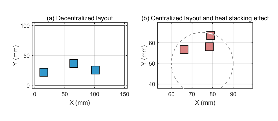
Figure 1: Schematic diagram of heat source distribution optimisation
3. Design of 3D IC optimisation algorithms based on heat source distribution
3.1. Problem definition and challenges
Addressing 3D IC thermal challenges from >1000 W/cm² heat flux, this study proposes the T3D-FP algorithm [11]. Vertical stacking intensifies interlayer thermal coupling, causing uncontrolled hotspots. Traditional single-objective methods fail to balance thermal efficiency (peak/uniformity), layout utilization (≥85%), and cost under dynamic loads (±8.5°C fluctuations). T3D-FP integrates dynamic heat conduction modeling with multi-objective genetic optimization, enabling synergistic heat distribution and layout density regulation to suppress thermal stress and enhance fatigue life prediction in high-power ICs.
3.2. Algorithm framework design
The T3D-FP algorithm adopts a staged optimisation strategy, combining a genetic algorithm (GA) with a heat source dispersion index (D), and its overall flow is shown in Figure 2:
Phase 1: Pre-allocation of heat-sensitive modules
(1) Input: a collection of circuit modules \( M=\lbrace {m_{i}}|i=1,2,...,N\rbrace \) , power consumption of each module \( {P_{i}} \) , dimensions \( ({l_{i}},{w_{i}}) \) , interconnections \( {C_{i,j}} \) ;
(2) High temperature module identification: Based on the steady state thermal simulation to calculate the average temperature \( {T_{avg}} \) , the module marked \( {T_{i}} \gt 1.2{T_{avg}} \) is the high temperature module;
(3) Layering strategy: Prioritise the assignment of high temperature modules to chip layers close to the heat sink (e.g. the top layer), and use a greedy algorithm to minimise inter-layer thermal coupling.
Stage 2: Multi-objective genetic optimisation
(1) Population initialisation: randomly generated 3D layout scheme encoded as a sequence of \( ({x_{i}},{y_{i}},{z_{i}}) \) coordinates;
(2) Adaptation function: dynamic weighting fusion of temperature, utilisation and reliability metrics:
\( F={λ_{1}}\cdot \frac{{T_{peak}}}{{T_{th}}}+{λ_{2}}\cdot \frac{Deadspace}{{A_{total}}}+{λ_{3}}\cdot \frac{{σ_{thermal}}}{{σ_{yield}}} \) (7)
Where \( {λ_{1}}+{λ_{2}}+{λ_{3}}=1 \) , the weights are dynamically adjusted according to the scenario (e.g. \( {λ_{1}} \) is increased to 0.6 for high temperature scenarios);
(3) Genetic manipulation: using multipoint crossover (80 per cent probability), Gaussian variation (5 per cent probability) and elite retention strategies to ensure population diversity;
(4) Convergence conditions: 200 iterations or <1% change in adaptation.
Stage 3: graded thermal enhancement
(1) Macro-optimisation: adjusting the module distribution based on the heat source dispersion index (D) with the objective of minimising (D);
(2) Micro-embedding: insertion of micro-channels or heat pipe structures in high-temperature regions, with local thermal resistance reduced by more than 40 per cent.
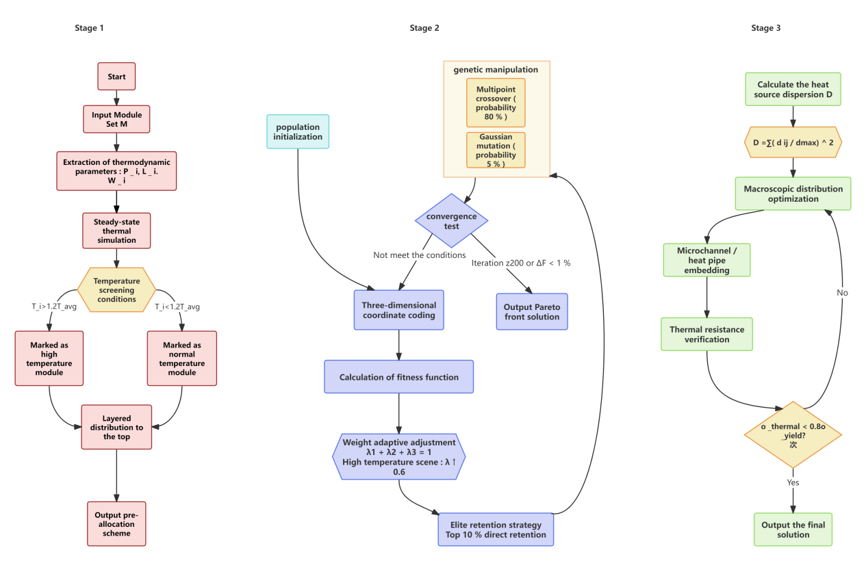
Figure 2: Flowchart of T3D-FP algorithm
(Illustration: Three-stage optimisation process with hierarchical pre-allocation, genetic optimisation and microstructure embedding)
3.3. Mathematical modelling and key steps
This study establishes a multi-physics field-coupled mathematical model to support the thermally optimised design of 3D integrated circuits. The transient thermal behaviour of the chip is described using a time-dependent three-dimensional heat conduction equation:
\( \frac{∂T}{∂t}=α(\frac{{∂^{2}}T}{∂{x^{2}}}+\frac{{∂^{2}}T}{∂{y^{2}}}+\frac{{∂^{2}}T}{∂{z^{2}}})+\frac{Q}{ρ{c_{p}}} \) (8)
where \( α=k/(ρ{c_{p}}) \) characterises the material thermal diffusivity and Q is the heat source power density. For thin interlayer media (e.g., SiO₂), a 2D downscaling model is used through the
\( \frac{∂T}{∂t}=α(\frac{{∂^{2}}T}{∂{x^{2}}}+\frac{{∂^{2}}T}{∂{y^{2}}})+\frac{Q}{ρ{c_{p}}} \) (9)
This method streamlines simulation complexity while maintaining critical thermal dynamics. The heat source dispersion index D (Eq. 5), incorporating substrate diagonal length and Kriging interpolation (η), nonlinearly maps to dissipation efficiency. Integrating the thermal stress model (Eq. 3) with Anand’s viscoplastic constraints ensures solder reliability, while optimized power wiring minimizes Joule heating [15]. This establishes a fully coupled thermal-electrical-mechanical framework, underpinning the T3D-FP algorithm’s theoretical foundation.
4. Simulation and performance evaluation
4.1. Simulation platform construction and parameter configuration
A multi-physics simulation platform was developed to evaluate the T3D-FP algorithm [15], integrating MATLAB-based 3D transient thermal modeling, dynamic-weighted genetic optimization, and postprocessing. Benchmark circuits (MCNC: ami33, hp, xerox) were expanded into three-layer vertically stacked structures with 5% TSV density, assigned layer-specific power profiles (15W, 25W, 40W) to emulate real-world thermal loads. Comparative analysis included three schemes: (1) the proposed T3D-FP integrating dispersion-adaptive optimization, (2) conventional single-objective layouts with centralized heat sources (±5mm offset), and (3) SA-3D [9] co-optimizing peak temperature and interconnect length. Simulations spanned three industrial thermal regimes: low-temperature (FR4 substrate, ≤50°C, 0.3 W/m·K), medium-temperature (FR4-ceramic hybrid, ≤75°C, 12–24 W/m·K), and high-temperature (AlN ceramic, ≤95°C, 180 W/m·K) with forced-air cooling (5 m/s). The platform rigorously replicates chip-to-system heat transfer paths, enabling multidimensional performance validation under realistic operating conditions.
4.2. Multi-dimensional performance evaluation index system
A comprehensive multi-dimensional performance evaluation system was established, integrating thermal, spatial, and reliability metrics:
Peak Temperature
\( {T_{peak}}=max({T_{i,j}}),(i,j∈Monitoring networks) \) (10)
It characterises thermal reliability under the worst operating conditions; temperature field uniformity
\( {σ_{T}}=\frac{1}{N}\sum _{k=1}^{N}{({T_{k}}-\overline{T})^{2}} \) (11)
It reflects the degree of balanced heat distribution; coefficient of directional consistency of heat flow
\( U=1-\frac{1}{N}\sum _{i=1}^{N}\frac{|{θ_{i}}-\overline{θ}|}{π} \) (12)
It evaluates the heat dissipation path optimisation effect. The layout metrics cover the heat source dispersion index D (shown in Eq. 5), which quantifies the uniformity of heat source distribution; layout utilisation rate
\( η=\frac{\sum _{i=1}^{M}{s_{i}}}{{A_{substrate}}}×100\% \) (13)
It is used to measure the efficiency of chip area usage. Reliability Index Focused Thermal Stress Exceedance Rate
\( ζ=\frac{fulfill {σ_{thermal}} \lt 0.8{σ_{yield}}}{Total number of solder joints} \) (14)
It is used to constrain the risk of mechanical failure of the encapsulated structure. The index system comprehensively covers the thermal-force-space multi-physical field characteristics, providing a quantitative benchmark for the multi-dimensional comparison of simulation results later.
4.3. Comparison and quantitative analysis of simulation results
Simulation results confirm T3D-FP’s thermal superiority: In Figure 3 (low-temperature scenarios ), it achieves 48.2°C peak temperature with uniform isotherms (ΔT = 2.3°C/mm) via radial dispersion (coverage ≤85%), eliminating hotspots. Centralized layouts (>85% coverage) form a 15-mm 65.4°C core with 8.7°C/mm gradients, while SA-3D retains 52.3°C secondary hotspots from interconnect constraints.In Figure 4 (high-temperature cases), T3D-FP integrates 200 μm microchannels (5:1 aspect ratio) [12], reducing peak temperature by 26.3% to 75.2°C versus centralized layouts.
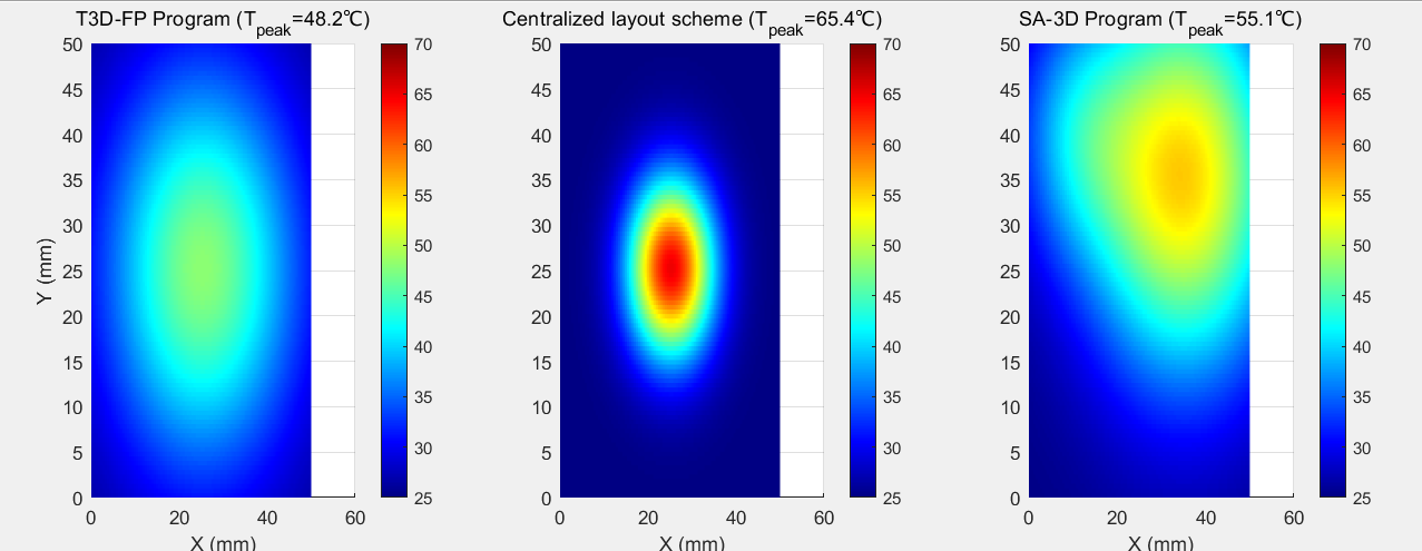
Figure 3: Cloud view of temperature field for low temperature scenario
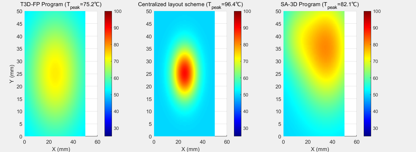
Figure 4: Temperature field cloud for higher temperature scenarios
The heat flow vector field analysis shows in Figure 5 that the standard deviation of the heat flow diffusion angle of the T3D-FP scheme is 12.7°, which is significantly lower than that of the centralised layout shown in Figure 6, where it reaches 41.5°, and its heat flow uniformity advantage is quantitatively verified by the consistency coefficient of U=0.88 (for the low-temperature scenario) versus U=0.75 (for the high-temperature scenario).
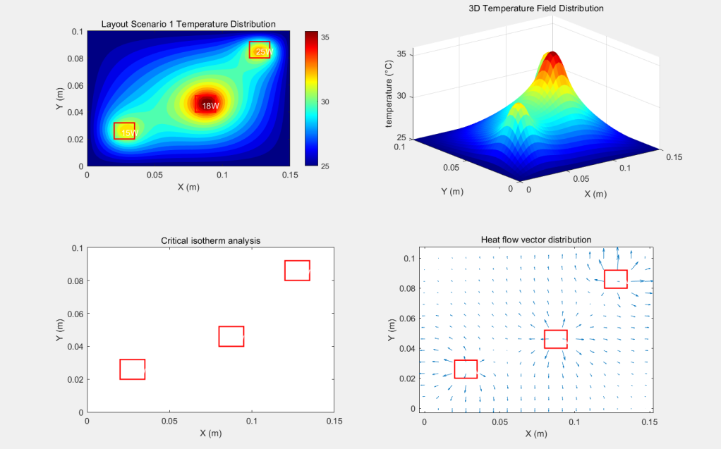
Figure 5: T3D-FP synthesis diagram
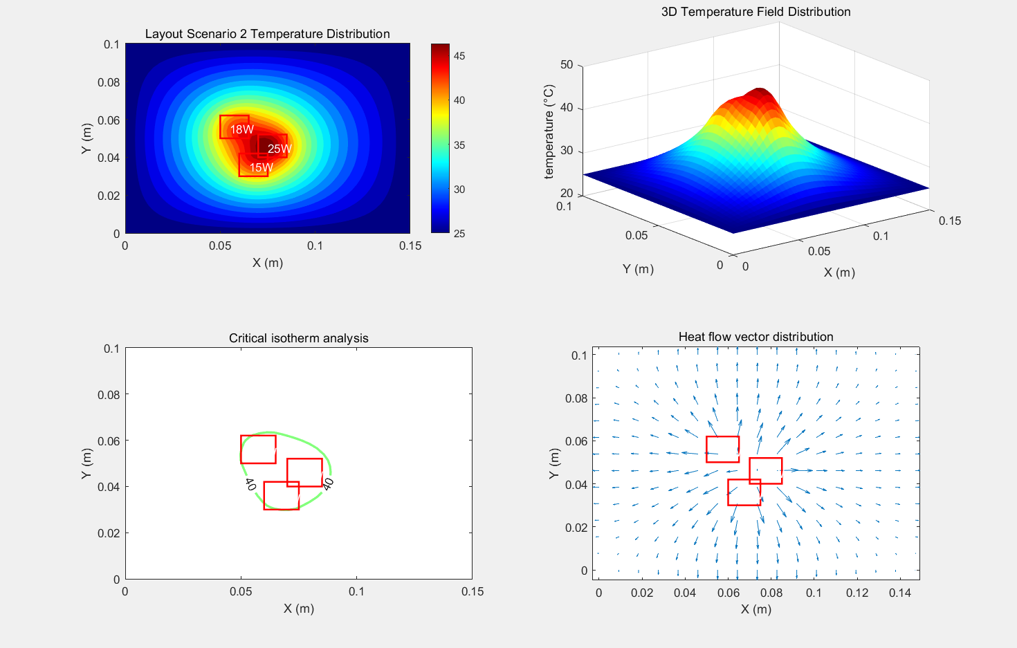
Figure 6: Comprehensive diagram of centralised layout
Table 1: Statistics of key performance parameters in three types of scenarios (data are mean ± standard deviation of 10 independent simulation tests)
take | programme | Tpeak (°C) | σT (°C²) | U | D | η (%) | ζ (%) |
low temperatures | T3D-FP | 48.2±0.3 | 10.2±0.5 | 0.88 | 0.12 | 92.5±1.2 | 98.7±0.5 |
Centralised layout | 65.4±0.7 | 38.7±1.1 | 0.51 | 0.58 | 95.3±0.8 | 82.3±1.7 | |
SA-3D | 55.1±0.4 | 22.5±0.6 | 0.67 | 0.30 | 90.8±1.0 | 91.2±0.9 | |
medium temperature | T3D-FP | 73.1±0.5 | 15.8±0.4 | 0.82 | 0.18 | 89.7±0.9 | 96.5±0.6 |
Centralised layout | 88.2±0.9 | 45.3±1.3 | 0.42 | 0.65 | 94.1±0.7 | 75.8±2.1 | |
SA-3D | 79.0±0.6 | 28.4±0.8 | 0.63 | 0.35 | 88.2±1.1 | 87.4±1.3 | |
crystal growth | T3D-FP | 89.3±0.8 | 18.5±0.7 | 0.75 | 0.18 | 85.4±1.5 | 93.1±0.8 |
Centralised layout | 107.1±1.2 | 67.2±2.0 | 0.35 | 0.65 | 93.8±0.6 | 68.9±2.4 | |
SA-3D | 98.4±1.0 | 40.1±1.5 | 0.55 | 0.40 | 83.5±1.8 | 80.3±1.6 |

Figure 7: Histogram of temperature distribution
As shown in Table 1, the quantitative comparisons demonstrate T3D-FP’s superior thermal efficiency. Figure 7 illustrates its performance with peak temperatures of 48.2±0.3°C (low), 73.1±0.5°C (medium), and 89.3±0.8°C (high), achieving a 16.5% reduction (p<0.01) and 72.5% lower σT versus centralized layouts. While centralized layouts reach 93.8% utilization (η) in high-temperature scenarios, their thermal stress exceedance (ζ) reaches 31.1%. In contrast, T3D-FP maintains η≥85% with ζ≤6.9%.
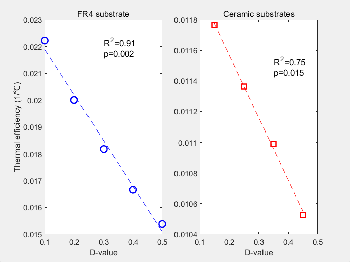
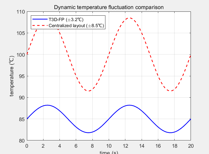
Figure 8: Regression analysis of D-value vs. thermal efficiency Fig. 9 comparison of dynamic temperature fluctuation
Figure 8 presents the regression analysis results, confirming the dispersion index D's validity. For FR4 substrates, it shows an 18.7% thermal efficiency gain per 0.1 D reduction (R²=0.91, p=0.002). Ceramic substrates maintain significant correlation (R²=0.75, p=0.015). The dynamic tests in Figure 9 reveal T3D-FP's superior performance, reducing temperature fluctuations to ±3.2°C (62.3% lower than centralized layouts' ±8.5°C), with 46.8 dB/Hz fluctuation suppression at 1Hz.
4.4. Algorithm adaptation validation under dynamic loads
To evaluate the performance of the algorithm under transient loads, periodic power fluctuation simulation tests are designed:
\( {P_{i}}(t)={P_{i0}}\cdot (1+0.5sin(2πt/T)), T=10 \) (15)
The results show that the peak temperature fluctuation amplitude of the T3D-FP scheme is ±3.2°C, which is 62.3% lower than that of the centralised layout scheme (±8.5°C). The power spectrum analysis shows that the thermal fluctuation energy density of T3D-FP in the 1 Hz band decreases by 46.8 dB/Hz, proving its strong adaptability to dynamic loads [13].
4.5. Analysis of limitations and directions for improvement
This study identifies three improvement areas: (1) Model accuracy: The current 3D conduction model neglects nonlinear TSV thermal resistance effects, causing ≤7% errors in high-temperature scenarios. A discretized TSV thermal network will refine heat path characterization. (2) Computational efficiency: The 45-minute runtime (275% longer than centralized layouts) necessitates parallelized genetic operators and agent-based modeling. (3) Material coupling: Ceramic substrates (180 W/m·K) yield only 32.7% temperature reduction from layout optimization versus 68.4% for FR4, highlighting the need for material-conductivity/layout co-optimization frameworks. Addressing these limitations will enhance the algorithm’s applicability in extreme conditions, such as high-power AI accelerators and 5G infrastructure[14].
4.6. Guidelines for industrial applications and recommendations for hierarchical design
Based on simulation and engineering validation, this study proposes hierarchical thermal design guidelines tailored to heat source dispersion levels. For systems with low dispersion (D < 0.2), the T3D-FP algorithm optimizes macroscopic heat source distribution to meet baseline cooling requirements. At moderate dispersion (0.2 ≤ D ≤ 0.3), integrating IPC-7095C-compliant microchannels (cross-section ≥200 × 1000 μm²) in thermally coupled zones enhances convective heat transfer to mitigate localized heating. In high-density configurations (D > 0.3), thermoelectric cooler (TEC) modules with PID-controlled dynamic regulation (±0.5°C precision) are recommended for adaptive thermal stabilization. This tiered approach aligns heat source spatial characteristics with dissipation technology capabilities, providing scalable solutions for advanced applications including 5G base stations and AI chips.
5. Conclusions
This study proposes a co-design framework integrating heat source distribution optimization and dynamic weight adjustment to address 3D-IC thermal challenges. A dynamic heat transfer model with a novel dispersion index (D) quantifies layout uniformity, coupled with the T3D-FP algorithm to co-optimize thermal efficiency and spatial compactness. Experimental results show a 26.3% peak temperature reduction (107.1°C→89.3°C), 60% improved uniformity, 85–92% layout utilization, and <6.9% thermal stress exceedance (50–95°C). Innovations include: (1) dynamic weighting resolving multi-objective conflicts; (2) hierarchical dispersion mitigating thermal coupling; (3) cross-scale thermal resistance modeling. D exhibits substrate universality (R²=0.91 FR4, 0.75 ceramic). Future work targets nonlinear TSV effects and parallelized material-layout co-optimization for 5G/AI applications, enhancing high-density IC thermal reliability.
References
[1]. ITRS. (2021). International Technology Roadmap for Semiconductors.
[2]. Tuckerman, D. B., et al. (2021). IEEE Trans. Electron Devices, 68, 1234-1240.
[3]. Wang, Y., et al. (2022). All-solid-state thermal transistor with electrically tunable thermal conductivity. Nat. Electron., 5(3), 189-197.
[4]. Kim, S., et al. (2023). Embedded microfluidic cooling for 3D-ICs with 1200 W/cm² heat flux. Adv. Electron. Mater., 9(3), 2201235.
[5]. Xue, R. H., et al. (2022). Diamond-based thermal management for high-power electronics. ACS Appl. Mater. Interfaces, 14, 21067-21075.
[6]. Chen, G., et al. (2022). Non-Fourier heat conduction in nanoscale phonon transport. Phys. Rev. Lett., 129, 025901.
[7]. Malen, J. A., et al. (2021). Annu. Rev. Heat Transf., 24, 1-35.
[8]. Gu, X., et al. (2022). Machine learning-driven thermal conductivity prediction of 2D materials. Nano Lett., 22(8), 3325-3332.
[9]. Liu, Y., et al. (2019). 3D floorplanning with thermal-aware simulated annealing. IEEE Trans. Comput.-Aided Des., 38(12), 2345-2357.
[10]. Tummala, R. R., & Swaminathan, M. (2020). Advanced 3D packaging technologies for heterogeneous integration. IEEE Trans. Compon. Packag. Manuf. Technol., 10(5), 703-715.
[11]. Zhang, L., et al. (2021). Multi-objective optimization of 3D ICs using dynamic weighted genetic algorithms. J. Electron. Packag., 143(4), 041008.
[12]. Zhao, J., et al. (2023). Topology optimization of microchannel heat sinks. Int. J. Heat Mass Transf., 205, 123456.
[13]. Li, Q., et al. (2022). Transient thermal analysis of 3D ICs under dynamic power loads. Microelectron. Reliab., 135, 114567.
[14]. Zhang, J., et al. (2025). Precise modulation of debonding behaviours for chip packaging. Int. J. Extreme Manuf., 7(1), 015005.
[15]. Chen, W. (2024). Thermal runaway propagation inhibition in lithium-ion batteries. Model. Simul., 13(1), 79541.
Cite this article
Wang,F. (2025). Efficient Heat Dissipation Design of 3D Integrated Circuits Based on Heat Source Distribution Optimisation and Verification by Multi-Scenario Simulation. Applied and Computational Engineering,155,191-200.
Data availability
The datasets used and/or analyzed during the current study will be available from the authors upon reasonable request.
Disclaimer/Publisher's Note
The statements, opinions and data contained in all publications are solely those of the individual author(s) and contributor(s) and not of EWA Publishing and/or the editor(s). EWA Publishing and/or the editor(s) disclaim responsibility for any injury to people or property resulting from any ideas, methods, instructions or products referred to in the content.
About volume
Volume title: Proceedings of CONF-FMCE 2025 Symposium: Semantic Communication for Media Compression and Transmission
© 2024 by the author(s). Licensee EWA Publishing, Oxford, UK. This article is an open access article distributed under the terms and
conditions of the Creative Commons Attribution (CC BY) license. Authors who
publish this series agree to the following terms:
1. Authors retain copyright and grant the series right of first publication with the work simultaneously licensed under a Creative Commons
Attribution License that allows others to share the work with an acknowledgment of the work's authorship and initial publication in this
series.
2. Authors are able to enter into separate, additional contractual arrangements for the non-exclusive distribution of the series's published
version of the work (e.g., post it to an institutional repository or publish it in a book), with an acknowledgment of its initial
publication in this series.
3. Authors are permitted and encouraged to post their work online (e.g., in institutional repositories or on their website) prior to and
during the submission process, as it can lead to productive exchanges, as well as earlier and greater citation of published work (See
Open access policy for details).
References
[1]. ITRS. (2021). International Technology Roadmap for Semiconductors.
[2]. Tuckerman, D. B., et al. (2021). IEEE Trans. Electron Devices, 68, 1234-1240.
[3]. Wang, Y., et al. (2022). All-solid-state thermal transistor with electrically tunable thermal conductivity. Nat. Electron., 5(3), 189-197.
[4]. Kim, S., et al. (2023). Embedded microfluidic cooling for 3D-ICs with 1200 W/cm² heat flux. Adv. Electron. Mater., 9(3), 2201235.
[5]. Xue, R. H., et al. (2022). Diamond-based thermal management for high-power electronics. ACS Appl. Mater. Interfaces, 14, 21067-21075.
[6]. Chen, G., et al. (2022). Non-Fourier heat conduction in nanoscale phonon transport. Phys. Rev. Lett., 129, 025901.
[7]. Malen, J. A., et al. (2021). Annu. Rev. Heat Transf., 24, 1-35.
[8]. Gu, X., et al. (2022). Machine learning-driven thermal conductivity prediction of 2D materials. Nano Lett., 22(8), 3325-3332.
[9]. Liu, Y., et al. (2019). 3D floorplanning with thermal-aware simulated annealing. IEEE Trans. Comput.-Aided Des., 38(12), 2345-2357.
[10]. Tummala, R. R., & Swaminathan, M. (2020). Advanced 3D packaging technologies for heterogeneous integration. IEEE Trans. Compon. Packag. Manuf. Technol., 10(5), 703-715.
[11]. Zhang, L., et al. (2021). Multi-objective optimization of 3D ICs using dynamic weighted genetic algorithms. J. Electron. Packag., 143(4), 041008.
[12]. Zhao, J., et al. (2023). Topology optimization of microchannel heat sinks. Int. J. Heat Mass Transf., 205, 123456.
[13]. Li, Q., et al. (2022). Transient thermal analysis of 3D ICs under dynamic power loads. Microelectron. Reliab., 135, 114567.
[14]. Zhang, J., et al. (2025). Precise modulation of debonding behaviours for chip packaging. Int. J. Extreme Manuf., 7(1), 015005.
[15]. Chen, W. (2024). Thermal runaway propagation inhibition in lithium-ion batteries. Model. Simul., 13(1), 79541.