


1. Introduction
As the innovation created, the quick development of the handling pace of computer chips and coordinated circuits alongside more modest aspects has caused a critical expansion in heat motion produced. To scatter the intensity produced while handling, some advanced cooling technique was created and applied for thermal administration, as miniature electro-mechanical framework (MEMS) including stage change materials, heat pipes, thermoelectric coolers, and microchannel heat sinks.[1] In the interim, contrasted and other cooling techniques, a microchannel heat sink shows phenomenal ability to scatter as a result of its little size, high heat exchange region, low thermal resistance, and high intensity move limit. Nonetheless, the microchannel heat sink additionally requires moderately high power during activities. Consequently concentrates on microchannel heat sinks are attempting to lessen the power required and improve the intensity move execution.
Derakhshanpour et al. [2] concentrated on the impacts of rib shape and filet range. In this review, they reproduced the microchannel heat sink with semi-circular and semi-elliptical ribs with and without fileted ribs and discussed the thermal performance of various designs. As indicated by this review, a microchannel heat sink with a rib will improve its thermal performance, and the fileted rib microchannel heat sink has preferred execution over non-fileted rib microchannel heat sink. Wang et al. [3] concentrated on the impacts of bidirectional rib in microchannel heat sink. In this review, they reproduced a microchannel heat sink with the bidirectional rib, vertical rib, and horizontal rib and discussed the thermal performance among these three unique designs. As per this review, the bidirectional microchannel heat sink has better thermal performance contrasted and others. Prajapati [4] concentrated on the impacts of fin height on heat transfer. In this review, Prajapati simulated a rectangular microchannel heat sink with various fin heights and discussed the thermal performance of various fin height. As per this review, expanding fin height empowers an increase in thermal performance and the pressure drop when fin height is lower than 0.8 mm, and the complete closed microchannel heat sink has lower thermal performance and higher pressure drop contrasted and the fin height at 0.8 mm. Wang et al. [ 5] concentrated on the impacts of geometric parameter and number of channels of microchannel heat sink. In this review, they contemplated the rectangular, triangular, and trapezoidal microchannel heat sink with various aspect ratios. As per this review, the rectangular microchannel heat sink with a high aspect ratio has the best thermal performance and most elevated pressure drop, and the thermal performance is likewise impacted by the quantity of channels. Tilak et al. [ 6] concentrated on the impacts of novel cross-section on thermal performance. In this review, they concentrated on the various sorts of cross-section shapes and discussed the thermal performance of each shape. As per this review, the inverted T shape with a circular end at the base(ITSCEB) has the most noteworthy thermal performance among all plans with the most noteworthy pressure drop punishment. Zhu et al. [ 7] discussed the impacts of various groove shapes on thermal performance. In this review, they examined microchannel heat sinks with rectangular, circular, triangular, water-droplet, and trapezoidal groove shapes with the same geometric parameters. As per this review, the grooves can upgrade thermal performance and lessen the pressure drop of the microchannel heat sink, with the exception of the rectangular section. Sun et al. [ 8] designed and reproduced another plan. In this review, they planned and contemplated the microchannel heat sink copying the Tesla valve(MCTV) and contrasted the thermal performance with a few different plans. As per this review, the MCTV has the best thermal-hydraulic performance among the designs in general, and the Nusselt number increments as r diminishes. Jeevan et al. [ 9] concentrated on the impacts of the double-layer microchannel heat sink on thermal performance. As indicated by this review, the double-layer microchannel heat sink has better thermal performance and higher pressure than the single-layer microchannel heat sink.
As indicated by studies discussed beforehand, all of the explores are predominantly centered around changing the plan and state of the microchannel heat sink. In any case, there is little data about the impacts of counter stream. Subsequently, the fundamental reason for this study is to talk about and research heat move and stream qualities of counter stream, in which the stream headings are inverse for two adjoining channels, joined with the different score shapes and plans, incorporating microchannel heat sink with rectangular groove(R-MCHS), semi-roundabout groove(C-MCHS), triangular groove(T-MCHS).
In this study, the designed model will be discussed in Section 2, and then the numerical method used in this study will be discussed in Section 3, including the Governing Equations, Solution Procedure, and Performance Parameter. Then the result and discussion will be stated in Section 4, coming up with conclusion.
2. Model
Fig. 1 shows the geometry of the microchannel heat sink. The parameters L, W, H are the length, width, and heights of the microchannel heat sink provided in Table 1. In light of the geometry and presumptions examined thusly in this paper, to lessen the intricacy of the reenactment, a delegate cell from the microchannel heat sink is chosen for demonstrating the microchannel heat sink.
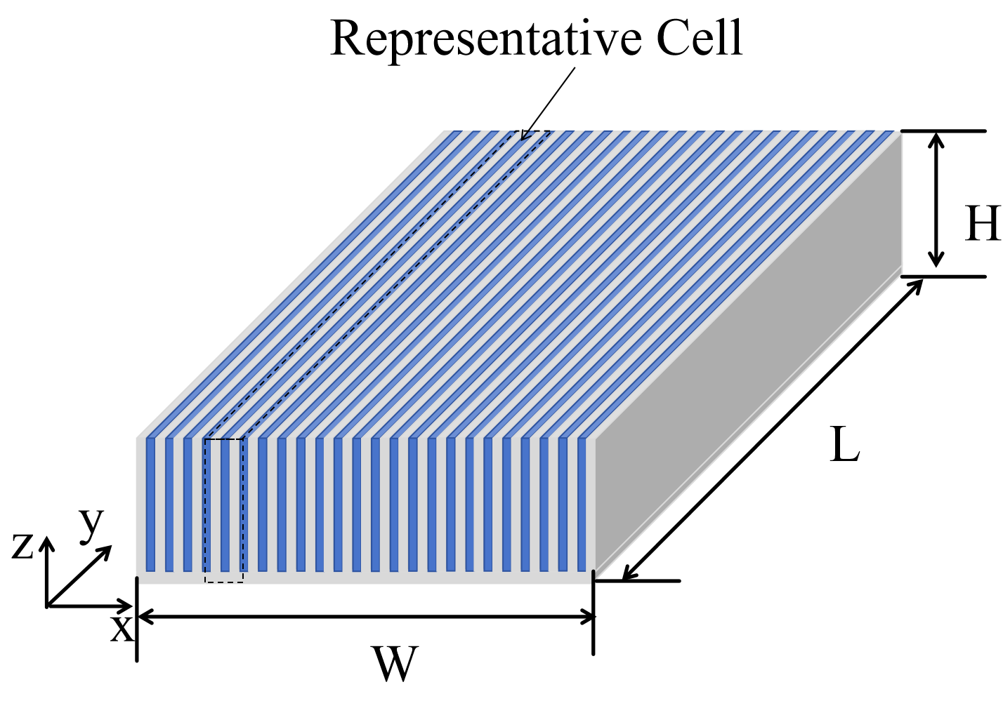
Figure 1. Model of whole Microchannel Heat Sink.
Fig. 2 shows the geometry of one representative cell for modeling the microchannel heat sink. Each cell contains two microchannels, and the flow directions of the two microchannels are opposite. The parameters WT, WC, HC are representative cell width, microchannel height, and microchannel distance, which are given in the Table 1. The created heat from electronic gadgets is caught by the base region of the microchannel heat sink and moved to the coolant liquid. The intensity move systems in the microchannel heat sinks are conduction in the strong aspect and convection in the fluid district.
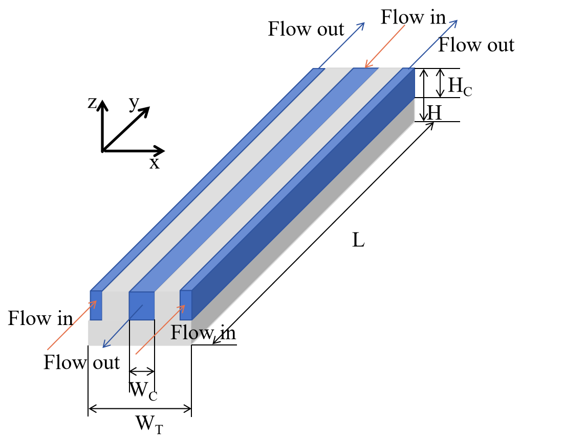
Figure 2. Model of Representative Cell Microchannel Heat Sink.
Fig. 3 illustrates 3 different configurations investigated in this study: Microchannel with rectangular grooves (R-MCHS), Microchannel with semi-circular grooves (C-MCHS), and Microchannel with triangular grooves (T-MCHS). Therefore the effects of counterflow on thermal performance and pressure drop can be investigated in these configurations. The simple conventional microchannel heat sink (S-MCHS) is also modeled to compare the potential improvements in flow and heat transfer performance. The parameters LD and LG are the distance between two grooves and the width of grooves, which is provided in Table 1. In this study, the Reynolds number varies from 100 to 500.
Table 1. Microchannel Heat Sink Geometric Parameters
Parameters | Value[mm] |
L | 10 |
W | 10 |
H | 0.25 |
LG | 1 |
LD | 0.05 |
WT | 0.5 |
WC | 0.1 |
HC | 0.2 |
|
|
|
|
(a) | (b) | (c) | (d) |
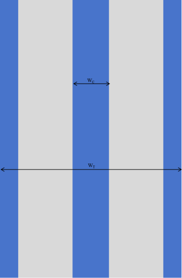
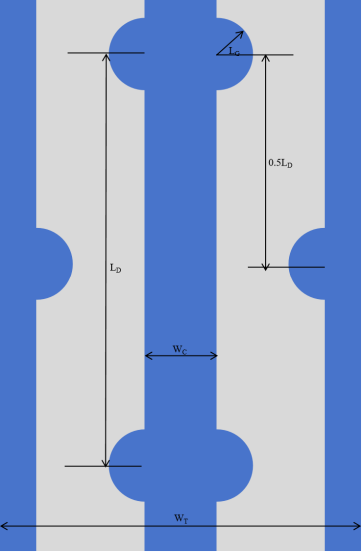
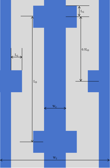
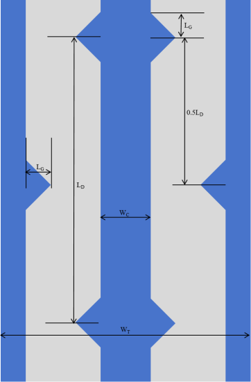
Figure 3. Microchannel Heat Sink Design of: a) S-MCHS, b) C-MCHS, c) R-MCHS, d) T-MCH.
3. Numerical Method
To numerically simulate the fluid flow and heat transfer inside microchannels, some assumptions have been made as below:
• Non-slip boundary conditions between fluid and solid domain.
• The flow is incompressible, laminar, and steady.
• The influence of radiation heat transfer and gravity are negligible.
• Properties of solid and fluid are considered to be constant except the viscosity and density of coolant fluid. (water viscosity and density vary with temperature of water)
• The effect of viscous dissipation of water flow is negligible.
3.1. Governing Equations and Boundary Conditions
Based on the assumption made above, the governing equations of the fluid domain, which are the continuity equation, momentum equation, and energy equation, can be laid out to portray the stream and intensity move qualities of microchannel heat sinks, as displayed underneath:
\( continuity: ∇·V= 0 \ \ \ (1) \)
\( momentum: {ρ_{f}} (V·(∇·V))=-∇p+∇({µ_{f}} (∇·V))\ \ \ (2) \)
\( energy: ρf cp,f (V·∇{T_{f}} )={k_{f}} {∇^{2}}{T_{f}}\ \ \ (3) \)
The energy equation for the solid regions is defined as Eq.4.
The energy equation of solid domain:
\( {k_{s}}∇2{T_{s}}=0\ \ \ (4) \)
where V is the speed vector of coolant liquid, p is the static pressure of coolant liquid, Tf and Ts are the static temperature of coolant liquid and microchannel, separately. ρf , cp, f , kf , µf show the density, specific heat capacity, thermal conductivity, and viscosity of coolant liquid.
Water is the coolant liquid and the microchannel is made of silicon. In view of the suspicion made already, the thermal conductivity and dynamic viscosity of water are temperature reliant and communicated by Eq.5 and Eq.6 that are acquired and relapse of information given by Ref.[10]. Different parameters of water and silicon are steady, given by Table 2
\( {k_{f}}(T)=0.9276-0.01116T+6.87×{10^{-5}}{T^{2}}-1.502×{10^{-7}}{T^{3}}+1.105×{10^{-10}}{T^{4}}(\frac{W·K}{m})\ \ \ (5) \)
\( {µ_{f}} (T)=381.5exp{(-0.0427T)}+0.01534exp{(0.01089T)}(\frac{kg}{m·s})\ \ \ (6) \)
Table 2. Physical Properties of water and silicon [11]
Material | ρ(kg/m3 ) | cp (J/kg/K) | k(W/m/K) | µ(kg/m/s) |
Water | 998.2 | 4181 | Eq.5 | Eq.6 |
Silicon | 2329 | 712 | 148 | - |
Based on assumption and governing equations defined, the boundary conditions are provided in Table 3.
In all equations, temperature is in Kelvin.
Table 3. The Boundary Conditions used in simulation
Zone | Boundary Condition | Expression |
Inlet | Velocity-inlet | At Inlet : u = uin , T = Tref |
Outlet | Pressure-outlet | At Outlet : pout = 0 |
Bottom Wall | Constant heat flux | z= 0 : −ks \( \frac{{∂T_{s}}}{{∂_{n}}} \) = qw = 106 \( \frac{W}{{m^{2}}} \) |
Left and Right Walls | Symmetry | x = 0 and x = WT : \( \frac{∂T}{{∂_{n}}} \) = 0 |
Inner Walls | No-Slip | u=v= w = 0, −ks \( \frac{{∂T_{s}}}{{∂_{n}}} \) = −kf \( \frac{{∂T_{f}}}{{∂_{n}}} \) |
Other Walls | Adiabatic | \( \frac{∂T}{{∂_{n}}} \) = 0 |
3.2. Solution Procedure
To solve the governing differential equations based on the finite volume method in fluid and solid domains, COMSOL Multiphysics software is utilized. In order to minimize the error of simulation, the relative error of each step is 10−4. To simplify the simulation and shorten the time of simulation, the grid in the y direction is less dense compared with the x and z directions, and the number of boundary layers is 3.
3.3. Performance Parameters
The result of simulations are used to find the parameter that can reflect thermal and hydraulic performances of microchannel heat sink. Therefore, some parameters are defined below:
The hydraulic diameter is defined as:
\( {D_{h}}= \frac{4{A_{c}}}{{P_{c}}}=\frac{2{W_{c}}·{H_{C}}}{WC + HC}\ \ \ (7) \)
where Ac is the cross-sectional area of microchannel, and Pc is the section perimeter of microchannel.
Reynolds number is expressed by:
\( {R_{e}}=\frac{ρf·{u_{in}}·{D_{h}}}{µf} \) (8)
where ρf is density of coolant fluid, uin is inlet velocity of fluid, and µf is the dynamic viscosity of fluid. Therefore, the inlet velocity can be defined as:
\( {u_{in}}=\frac{{R_{e}}·µf}{ρf·{D_{h}}} \) (9)
The convection coefficient h is defined as:
\( h=\frac{Q}{Acon(Tcon - T f )}=\frac{qLW}{Acon(Tcon - T f )} \) (10)
where Q is the total power provided on the bottom surface, Acon is the total area of convection, Tcon is the average temperature of convection surface, Tf is average temperature of fliud domain.
The thermal resistance of microchannel heat sink is defined as:
\( {R_{th}}=\frac{Ts -{T_{f}} }{Q}=\frac{Ts -{T_{f}} }{qAb} \) (11)
where Ts is the average temperature of solid and fluid domain, q is the constant heat flux applied on the bottom surface, and Ab is the bottom surface area of the microchannel heat sink.
The pumping power of microchannel heat sink is defined as:
\( Pp=N·Ac·uin ·∆p \) (12)
where Pp is the pumping power required of microchannel heat sink, N is the number of channels, ∆p is the total pressure drop between the inlet and outlet of channel. And the number of channel can be calculated as:
\( N=\frac{W}{\frac{{W_{T}}}{2}}=40 \) (13)
4. Result and Discussion
4.1. Model Validation
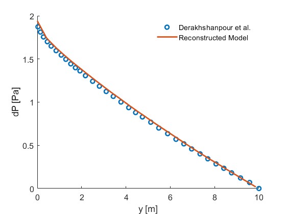
In order to validate the model built in this study, straight MCHS designed by Derakhshanpour et al.[2] is reconstructed based on our model. Variation in pressure drop along with the microchannel heat sink center line for S-MCHS by Derakhshanpour et al. and reconstructed design in this study at Re = 190 is provided in Fig. 4. As shown, the pressure drop along the center line of microchannel heat sink of reconstructed model is close to the reference data, with approximate relative error not exceeding 10%. Therefore, the model created in this study is validated.
4.2. Change in Thermal Resistance
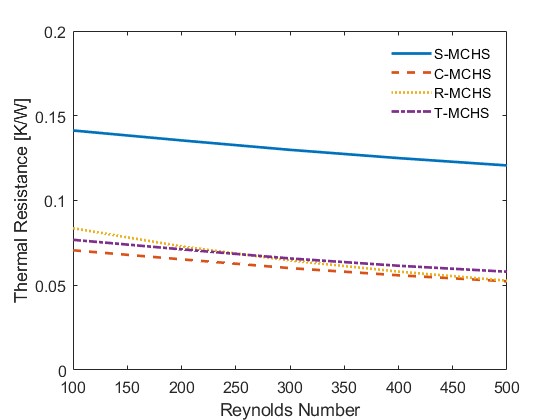
As the Reynolds number changes, the inlet velocity of fluid changes as well. Therefore, the temperature of the system is changed. The parameter that describes the temperature of the system, thermal resistance is also changed with the Reynolds number. The thermal resistance changes with the Reynolds number are illustrated in Fig. 5 below. For all types of MCHS, the general trend of thermal resistance decreases as the Reynolds number increases. Compared with the S-MCHS, the other three types of MCHS have relatively low heat resistance for any Reynold numbers. C-MCHS and T-MCHS have similar trends of changing heat resistance with different offsets. The offset of heat resistance of C-MCHS is lower than the T-MCHS. The heat resistance decreases much faster as the Reynolds number increases for the R-MCHS, but the heat resistance at any Reynolds number is higher than T-MCHS.
|
Figure 4. Model Validation of reconstructed straight MCHS designed in Derakhshanpour et al.[2]. |
|
Figure 5. Thermal Resistance change with Reynolds number for different types of MCHS. |
4.3. Temperature Distribution
Except for these parameters talked about previously, there is a direct way to show the capability of heat dissipation for MCHS, which is the temperature distribution. The temperature distributions of all cases in the XZ plane with y = 0.5L for Re = 500 are illustrated in Fig. 6(the region that is more red means that the temperature is higher, and the region that is more blue means that the temperature is lower). As shown, the temperature in the solid domain has a big change among these 4 different cases. The temperature of R-MCHS in the solid domain has the lowest temperature, and the circular domain has higher solid domain temperature than the R-MCHS, and the T-MCHS has the highest solid temperature except the S-MCHS.
Temperature distributions of different designs in XY plane with z = 0.5HT for Re = 500 are illustrated in Fig. 7. The same color scale is applied in Fig. 7 as shown in Fig. 6. According to Fig. 7, the overall temperature of R-MCHS is the lowest among all different designs, the C-MCHS has a higher temperature compared with R-MCHS, and T-MCHS has the highest temperature except S-MCHS. For all cases, the temperature distributions in the solid domain in the XY plane looks like normal distribution that the peak of temperature located at the middle of each cell, and the lowest temperature in the solid domain located at the end of each cell. Temperature difference in XY plane for R-MCHS is lowest, and the T-MCHS is the highest except for S-MCHS, and C-MCHS is in the middle.
|
|
|
|
(a) | (b) | (c) | (d) |
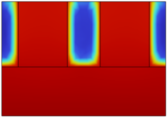
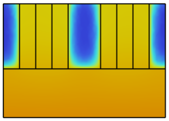
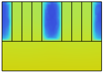
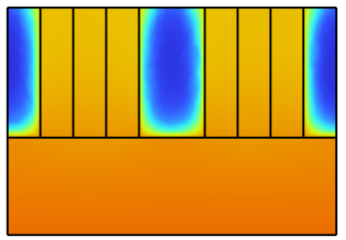
Figure 6. Temperature Distribution in XZ plane with y=0.5L of a) S-MCHS,b) C-MCHS, c) R-MCHS, d) T-MCHS.
|
|
(a) | (b) |
|
|
(c) | (d) |
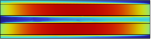
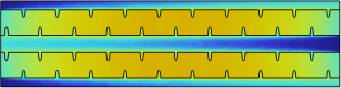
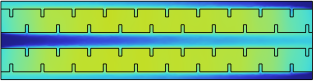
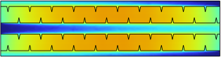
Figure 7. Temperature Distribution in XY plane of: a) S-MCHS, b) C-MCHS, c)R-MCHS, d) T-MCHS.
The average temperature in the solid domain is the best way to directly show the ability to dissipate heat from the heat source. The average temperature in the solid domain varying with the Re is illustrated in Fig. 8. As shown, the average temperature decreases as the Re increases, and the average temperature in the solid domain of R-MCHS is the lowest for any Re between 100 to 500. Therefore, based on the discussion we talked about previously, R-MCHS has the greatest ability to transfer heat from the heat sources and keep the overall temperature as low as possible, the T-MCHS has the least ability, and the C-MCHS is in the middle.
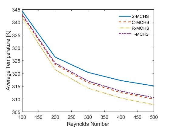
Figure 8. Average Temperature in Solid Domain for different design.
4.4. Change in Pumping Power
Another important parameter to quantitatively describe the performance MCHS is the pumping power. We want to not only have a better capacity to transfer the heat out of the heat source, but also minimize the work or power that consumed during this process, and the pumping power can quantitatively define how much power we need to use these MCHS. According to the equation of pumping power talked about previously, the pumping power relates to the pressure drop between the inlet and outlet, the cross-sectional area at the inlet, the inlet velocity for the same Reynolds number, and number of channels. For the model we talked about previously, for different types of MCHS talked about, the number of channels, cross-sectional area at the inlet, and velocity are the same across 4 different types. Therefore, the differences between pumping power among these types of MCHS only relate to the pressure drop between the inlet and outlet of the channel. The pumping power changing with Reynolds number are illustrated in Fig. 9. As the Reynolds number increases, the general trend of all 4 types of MCHS increases, because increasing the Reynolds number will increase the inlet velocity directly, and will change the inlet pressure as well. Among different designs, the R-MCHS has the highest pumping power for any Reynolds number, and C-MCHS and T-MCHS have close pumping power for any Reynolds number.
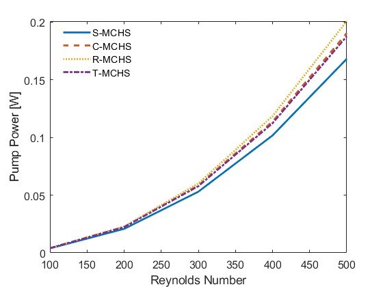
Figure 9. Pumping Power change with Reynolds Number for different types of MCHS.
4.5. Change in Fluid Velocity
Therefore, what causes these differences in the temperature distribution and parameters between each design? The fluid velocity may be one of the important factors. The fluid velocity for different designs at Re = 500 is illustrated in Fig. 10. From Fig. 10a, without any disturbance on the side wall of the channel, the velocity decreases from the center to the side wall, because of the non-slip boundary. As we described previously, the non-slip boundary will cause the velocity gradients between the wall and the center of fluid, forming a steady boundary condition on the side wall. However, for Fig. 10b to Fig. 10d, there exists a disturbance on the side wall. The disturbance breaks the steady boundary condition at those grooves location.
|
|
(a) | (b) |
|
|
(c) | (d) |
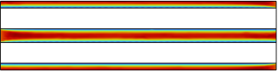
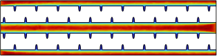

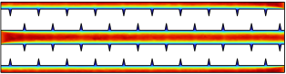
Figure 10. Velocity Distribution in XY plane of: a) S-MCHS, b) C-MCHS, c) R-MCHS, d) T-MCHS.
The detailed velocity distribution with the field line is illustrated in Fig. 11. As shown in Fig. 11, the field line of fluid is uniformly distributed when the grooves do not appear on the side wall, which is the same as shown in Fig. 11a. When the grooves are shown on the side wall, inside of the grooves, the vortex appears and destroys the steady boundary condition formed in the steady flow. At the downstream of grooves, there exists a stagnation point, because the flow direction is pointing perpendicular towards the wall in R-MCHS, and with some certain angle for C-MCHS and T-MCHS. At the groove location, the flow is separated into two sections, one of which forms the vortex inside the groove and takes heat out of it. Therefore, when the vortex occurs, it will enhance the capability of thermal convection and intensity of fluid mixing, as shown in Fig. 12 with the Re = 500. Based on the equation of the Nusselt Number and temperature distribution talked about previously, for calculating the Nusselt number, it is acceptable to use the average temperature of the solid domain as the average temperature of the convection surface. Therefore, as shown in Fig. 12, the Nusselt number of groove cases has significantly increased at the groove location, the R-MCHS has the greatest increment of Nusselt number, and the T-MCHS has the least increment. Increasing in Nusselt number means increasing convection, which can dissipate more heat from the solid domain, and decrease the overall temperature of the system.
|
|
|
|
(a) | (b) | (c) | (d) |
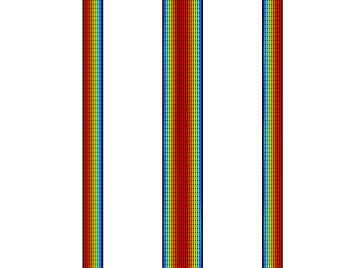
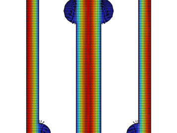
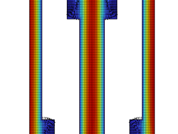
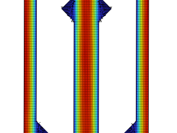
Figure 11. Detailed Velocity Distribution at groove location of : a) S-MCHS, b) C-MCHS, c) R-MCHS, d) T-MCHS.
4.6. Change in Fluid Pressure
As we discussed previously, the grooves on the side wall cause vortexes, which will enhance the heat transfer capabilities of MCHS. However, the grooves can not only enhance the heat transfer capability but also raise the required pressure and pumping power of MCHS. The pressure distribution of different designs of MCHS is shown in Fig. 13. As shown, the pressure distribution along the xy plane are relatively linear. Because of the friction between the side wall and bottom wall of the channel, the pressure gradually decrease along the flow direction. Nevertheless, as evidenced by detail pressure profile as illustrated in Fig.14 (red means higher pressure, blue means lower pressure, and black line is the equal-pressure line), at grooves, the downstream grooves have some high-pressure area, which correspond to the stagnation point in the previous chapter, and also a low-pressure area at the upstream of grooves. Because of the uneven distribution of pressure, the friction between the side wall and stream will be increased, causing an increase in pressure drop and pumping power as shown previously.
|
|
(a) | (b) |
|
|
(c) | (d) |

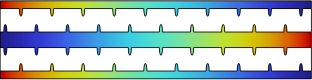
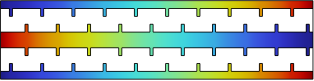
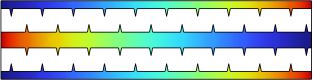
Figure 13. Pressure Distribution in XY plane of: a) S-MCHS, b) C-MCHS, c) R-MCHS, d) T-MCHS.
|
|
|
|
(a) | (b) | (c) | (d) |
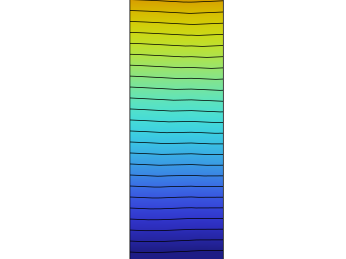
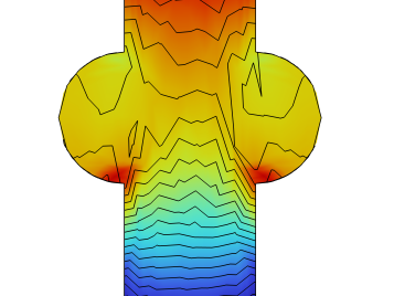
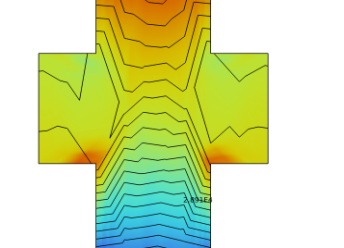
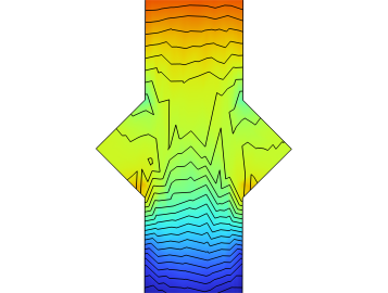
Figure 14. Detailed Pressure Distribution at groove location in XY plane of: a) S-MCHS, b) C-MCHS, c) R-MCHS, d) T-MCHS.
5. Conclusion
As we examined already, the impact of counterflow joined with various section shapes has been mathematically contemplated. Several different configurations of MCHS have been explored for the Re range from 100 to 500. In view of the examination discussed previously, a few significant conclusions have been established:
• By applying the counter stream to the microchannel heat sink, the temperature distribution turns out to be more uniform alongside the stream direction. The greatest temperature of different designs happens at the focal point of every agent cell.
• By adding the grooves the side wall, the average temperature of the solid domain decreases in a wide range of section microchannel heat sinks. The least temperature is the R-MCHS, trailed by C-MCHS and T-MCHS.
• The thermal resistance decreases as the Re expanding, and the T-MCHS and C-MCHS have a similar pace of decline as the expanding of Re, and the thermal resistance of R-MCHS diminishes quicker as Re expanding. Contrasted and S-MCHS, the thermal resistance is essentially expanded for all MCHS with groove, the warm obstruction of C-MCHS is the least, trailed by the T-MCHS for Re less than 250 and R-MCHS for Re greater than 250.
• The pumping power increments as the Re expanding, the pumping power of R-MCHS is the quickest expanding with the Re, trailed by the C-MCHS and T-MCHS. Contrasted and S-MCHS, the pumping power is expanded for all MCHS with grooves, the pumping power of R-MCHS is the most elevated, trailed by C-MCHS and T-MCHS for all Re between 100 to 500..
• The general performance is close between C-MCHS and T-MCHS, including the temperature distribution, thermal resistance, and pumping power. The performance is better for C-MCHS with the punishment of higher pumping power.
5.1. Limitation and Future Trend
This paper theoretically predicts the advantages of the designed structure, but the feasibility needs to be further verified experimentally. The conclusions of the study are applicable to the uniform heat flow density, for the case of uneven heat dissipation surfaces or the presence of hot spot, the conclusions of this paper need to be further analyzed.
The design of this paper is an independent heat sink, while heat sinks are generally used in combination with actual chips or specific heat dissipation elements, and a match is needed between the heat dissipation requirements and the optimal structure of the heat sink. In the future, further designs can be made in this area. And also, algorithms such as artificial intelligence or machine learning can be referenced and used to optimize heat sink performance.
Nomenclature | |
Ab | Bottom Surface Area of Microchannel Heat sink, m2 |
Ac | Cross Sectional Area of Channel, m2 |
Acon | Total Convection Area of Channel, m2 |
cp,f | Specific Heat Capacity of Water, Jkg−1K−1 |
Dh | Hydraulic Diameter, m |
H | Total Height of Microchannel Heat Sink, m |
HC | Height of Channel, m |
h | Coefficient of Convection |
kf | Coefficient of Thermal Conduction of Water, Wm−1K−1 |
ks | Coefficient of Thermal Conduction of Silicon, Wm−1K−1 |
L | Total Length of Microchannel Heat Sink, m |
LD | Distance between each groove, m |
LG | Depth of Groove, m |
N | Number of Channel |
Nu | Nusselt Number |
P | Pumping Power, W |
PP | Pressure of Water, Pa |
Pout | Pressure at Outlet, Pa |
Q | Total Heat Generated on the Bottom Surface, W |
qw | Heat Flux Generated on the Bottom Surface, Wm−2 |
Re | Reynold’s Number |
Rth | Thermal Resistance, KW−1 |
Tf | Temperature of Water, K |
Ts | Temperature of Silicon, K |
uin | Inlet Velocity, ms−1 |
V | Velocity Vector of Water, ms−1 |
W | Total Width of Microchannel Heat Sink, m |
WC | Width of Channel, m |
WT | Width of Representative Cell, m |
Greek Letter: | |
µf | Dynamic Viscosity of Water, kgm−1s−1 |
ρf | Density of Water, kgm−3 |
ρs | Density of Silicon, kgm−3 |
References
[1]. A. Dewan and P. Srivastava, “A review of heat transfer enhancement through flow disruption in a microchannel,” Journal of Thermal Science,vol. 24, pp. 203–214, 2015.
[2]. K. Derakhshanpour, R. Kamali, and M. Eslami, “Effect of rib shape and fillet radius on thermal-hydrodynamic performance of microchannel heat sinks: A cfd study,” International Communications in Heat and Mass Transfer, vol. 119, p. 104928, 2020.
[3]. W. Guilian, Q. Nan, and D. Guifu, “Heat transfer enhancement in microchannel heat sink with bidirectional rib,” International Journal of Heat and Mass Transfer, vol. 136, pp. 597–609, 2019.
[4]. Y. K. Prajapati, “Influence of fin height on heat transfer and fluid flow characteristics of rectangular microchannel heat sink,” International Journal of Heat and Mass Transfer, vol. 137, pp. 1041–1052, 2019.
[5]. W. Hongtao, C. Zhihua, and G. Jianguo, “Influence of geometric parameters on flow and heat transfer performance of micro-channel heat sinks,” Applied Thermal Engineering, vol. 107, pp. 870–879, 2016.
[6]. A. K. Tilak and R. S. Patil, “Study on Effects of Novel Cross Sections of Microchannel Heat Sink on Thermohydraulic Performance,” Journal of Heat Transfer, vol. 142, p. 044506, 02 2020.
[7]. Z. Qifeng, X. Huixue, C. Junjie, Z. Xinmin, C. Kunpeng, Z. Hongwei, W. Hua, W. Jianfeng, and J. Yangyang, “Fluid flow and heat transfer characteristics of microchannel heat sinks with different groove shapes,” International Journal of Thermal Sciences, vol. 161, p. 106721, 2021.
[8]. S. Li, L. Juan, X. Hao, M. Jie, and P. Hao, “Numerical study on heat transfer and flow characteristics of novel microchannel heat sinks,” International Journal of Thermal Sciences, vol. 176, p. 107535, 2022.
[9]. K. Jeevan, I. Azid, and K. Seetharamu, “Optimization of double layer counter flow (dlcf) micro-channel heat sink used for cooling chips directly,” in Proceedings of 6th Electronics Packaging Technology Conference (EPTC 2004) (IEEE Cat. No.04EX971), pp. 553–558, 2004.
[10]. R. Turner, J. Cimbala, and D. Yunus A. Cengel, Fundamentals of Thermal-Fluid Sciences. McGraw-Hill Education, 2016.
[11]. L. Yifan, X. Guodong, J. Yuting, M. Dandan, C. Bo, and W. Jun, “Effect of geometric configuration on the laminar flow and heat transfer in microchannel heat sinks with cavities and fins,” Numerical Heat Transfer, Part A: Applications, vol. 71, no. 5, pp. 528–546, 2017.
Cite this article
Liu,R. (2024). Thermal-Hydraulic performance of microchannel heat sink designed with counter-flow and different groove shape. Theoretical and Natural Science,31,81-93.
Data availability
The datasets used and/or analyzed during the current study will be available from the authors upon reasonable request.
Disclaimer/Publisher's Note
The statements, opinions and data contained in all publications are solely those of the individual author(s) and contributor(s) and not of EWA Publishing and/or the editor(s). EWA Publishing and/or the editor(s) disclaim responsibility for any injury to people or property resulting from any ideas, methods, instructions or products referred to in the content.
About volume
Volume title: Proceedings of the 3rd International Conference on Computing Innovation and Applied Physics
© 2024 by the author(s). Licensee EWA Publishing, Oxford, UK. This article is an open access article distributed under the terms and
conditions of the Creative Commons Attribution (CC BY) license. Authors who
publish this series agree to the following terms:
1. Authors retain copyright and grant the series right of first publication with the work simultaneously licensed under a Creative Commons
Attribution License that allows others to share the work with an acknowledgment of the work's authorship and initial publication in this
series.
2. Authors are able to enter into separate, additional contractual arrangements for the non-exclusive distribution of the series's published
version of the work (e.g., post it to an institutional repository or publish it in a book), with an acknowledgment of its initial
publication in this series.
3. Authors are permitted and encouraged to post their work online (e.g., in institutional repositories or on their website) prior to and
during the submission process, as it can lead to productive exchanges, as well as earlier and greater citation of published work (See
Open access policy for details).
References
[1]. A. Dewan and P. Srivastava, “A review of heat transfer enhancement through flow disruption in a microchannel,” Journal of Thermal Science,vol. 24, pp. 203–214, 2015.
[2]. K. Derakhshanpour, R. Kamali, and M. Eslami, “Effect of rib shape and fillet radius on thermal-hydrodynamic performance of microchannel heat sinks: A cfd study,” International Communications in Heat and Mass Transfer, vol. 119, p. 104928, 2020.
[3]. W. Guilian, Q. Nan, and D. Guifu, “Heat transfer enhancement in microchannel heat sink with bidirectional rib,” International Journal of Heat and Mass Transfer, vol. 136, pp. 597–609, 2019.
[4]. Y. K. Prajapati, “Influence of fin height on heat transfer and fluid flow characteristics of rectangular microchannel heat sink,” International Journal of Heat and Mass Transfer, vol. 137, pp. 1041–1052, 2019.
[5]. W. Hongtao, C. Zhihua, and G. Jianguo, “Influence of geometric parameters on flow and heat transfer performance of micro-channel heat sinks,” Applied Thermal Engineering, vol. 107, pp. 870–879, 2016.
[6]. A. K. Tilak and R. S. Patil, “Study on Effects of Novel Cross Sections of Microchannel Heat Sink on Thermohydraulic Performance,” Journal of Heat Transfer, vol. 142, p. 044506, 02 2020.
[7]. Z. Qifeng, X. Huixue, C. Junjie, Z. Xinmin, C. Kunpeng, Z. Hongwei, W. Hua, W. Jianfeng, and J. Yangyang, “Fluid flow and heat transfer characteristics of microchannel heat sinks with different groove shapes,” International Journal of Thermal Sciences, vol. 161, p. 106721, 2021.
[8]. S. Li, L. Juan, X. Hao, M. Jie, and P. Hao, “Numerical study on heat transfer and flow characteristics of novel microchannel heat sinks,” International Journal of Thermal Sciences, vol. 176, p. 107535, 2022.
[9]. K. Jeevan, I. Azid, and K. Seetharamu, “Optimization of double layer counter flow (dlcf) micro-channel heat sink used for cooling chips directly,” in Proceedings of 6th Electronics Packaging Technology Conference (EPTC 2004) (IEEE Cat. No.04EX971), pp. 553–558, 2004.
[10]. R. Turner, J. Cimbala, and D. Yunus A. Cengel, Fundamentals of Thermal-Fluid Sciences. McGraw-Hill Education, 2016.
[11]. L. Yifan, X. Guodong, J. Yuting, M. Dandan, C. Bo, and W. Jun, “Effect of geometric configuration on the laminar flow and heat transfer in microchannel heat sinks with cavities and fins,” Numerical Heat Transfer, Part A: Applications, vol. 71, no. 5, pp. 528–546, 2017.