


1. Introduction
Cancer is the second most common cause of death in the United States, with about two million new cancer cases each year. Recently the mortality rate dropped 32% from its peak in 1991, and a large part of this progress is due to early detection [1]. More progress is needed, and a promising direction is called a liquid biopsy [2]. Cancer metastasizes, or spreads, in the bloodstream making it possible to eventually detect cancer in a blood test. However, in a 7.5 ml blood sample there are only tens of circulating tumor cells (CTC), making separating, detection, and analysis of these cells very difficult [3]. A wide range of methods for performing the separation, or enrichment task are under development, and each has benefits and challenges. The number or density of CTCs is important to measure the impact of treatments, and molecular analysis of these intact cells provides key information for personalizing care. Many separation methods, like filtration can damage the CTCs [4].
The Segre-Silberberg effect, first described by [5], is a phenomenon in which suspended particles within a cylindrical tube of fluid are forced towards an annular ring as they move through the tube. This occurs because the particles near the wall of the tube are pushed towards the center, while those near the center are pushed outward towards the wall. A stable equilibrium for the particles is found in this annular ring, which is referred to as the Segre-Silberberg ring. The location of this ring is dependent on several factors, including the Reynolds number of the flow, the length of the tube, the velocity of the particles, and the ratio of the particle radius to the tube radius.
Several studies, including those by [6-8], have demonstrated that the position of the Segre-Silberberg annulus is strongly influenced by both the Reynolds number and particle size. Specifically, as the Reynolds number of a Poiseuille flow increases, the Segre-Silberberg annulus moves closer to the wall of the tube. At higher Reynolds numbers (Re \( \gt \) 600), another ring called the inner annulus appears in the tube, and an increasing number of particles accumulate in this region compared to the Segre-Silberberg annulus ([6]). Both the Segre-Silberberg annulus and the inner annulus are characterized by a stable equilibrium for the particles, as the lift force constantly pushes the particles back into place. However, the lift force in both annuli is less than that of any other radii in the tube apart from the center, where there is no lift, but particles do not settle due to the unstable equilibrium. Downstream in the tube, particles tend to land on the inner annulus less frequently.
In modern biochemical and pharmaceutical microfluidic devices, particle separation is a crucial process used for various applications, such as cell sorting, disease diagnosis, and drug discovery ([9]). Conventional techniques used for particle separation include size-based separation, charge-based separation, and magnetic separation. However, these methods often have limitations in terms of their efficiency, sensitivity, and specificity [10].
The Segre-Silberberg and associated Dean’s effect [11] presents a promising approach for particle separation through microfluidics, particularly for liquid cancer biopsy. This technique involves suspending cancer cells in a fluid, which is then passed through a microfluidic device with a narrow and often bent channel. As the fluid stream flows through the channel, the lift forces generated by the Segre-Silberberg effect focus the cancer cells at specific positions in the channel based on their size and position within the fluid. This allows for the efficient and precise isolation of cancer cells, which can then be sampled and analyzed for specific cancer markers or genetic mutations.
The Segre-Silberberg effect has several advantages over traditional separation techniques. Firstly, it is a non-invasive and label-free method, meaning that it does not require any modifications to the cancer cells or the fluid. Additionally, it is highly efficient and can separate many cancer cells in a short amount of time. The technique is also highly precise and can separate cancer cells based on subtle differences in their size or position within the fluid. Finally, the Segre-Silberberg effect is relatively cost-effective compared to traditional separation techniques, as it does not require specialized equipment or reagents.
In conclusion, the Segre-Silberberg effect has the potential to revolutionize liquid cancer biopsy by providing a non-invasive, efficient, and precise method for isolating and analyzing cancer cells in a highly controlled and economic manner. This technique has broad applications in the field of microfluidics and can be used for various other separation processes beyond cancer diagnosis and treatment.
In this study, we aimed to investigate the applicability of openFOAM [12], a computational fluid dynamics solver, in modelling the Segre-Silberberg effect. Through numerical simulations, we were able to verify that openFOAM can effectively model the phenomenon. We then utilized the validated model to test a design for a microfluidic device intended for liquid cancer biopsy. Our simulations revealed that the device was successful in utilizing the Segre-Silberberg effect and Dean’s effect to focus cancer cells at specific locations within the microchannel. This approach offers a promising method for efficient and accurate separation and analysis of cancer cells in a non-invasive and cost-effective manner. Additionally, the numerical simulations provide a valuable tool for designing and optimizing microfluidic devices for liquid cancer biopsy, ultimately contributing to the development of more effective cancer diagnosis and treatment methods.
2. Fluid Dynamics Background
A particle in a fluid flow with variable velocity profile such as the parabolic velocity profile in Poiseuille flow experiences forces applied towards or away from the wall depending on size of the particle, distance to the wall, and velocity profile of the flow. The exact solution of the flow profile of the Poiseuille flow is given by [13]:
\( v(r, t)=\frac{G}{4μ}({R^{2}}-{r^{2}})-\frac{2G{R^{2}}}{μ}\sum _{n=1}^{∞}\frac{1}{λ_{n}^{3}}\frac{{J_{0}}({λ_{n}}r/R)}{{J_{1}}({λ_{n}})}{e^{-λ_{n}^{2}νt/{R^{2}}}} \) (1)
where \( v(r, t) \) is the longitudinal velocity of the flow at radius \( r \) and time \( t \) , \( G=-\frac{dp}{dx} \) is the pressure gradient in the tubular flow, \( μ \) is the dynamic viscosity, \( ν \) is the kinematic viscosity, \( R \) is the radius of the tube, \( {J_{0}}(\frac{{λ_{n}}r}{R}) \) is the Bessel function of the first kind of order zero and \( {λ_{n}} \) are the positive roots of this function and \( {J_{1}}({λ_{n}}) \) is the Bessel function of the first kind of order one. As \( t→∞ \) , Poiseuille flow’s quadratic velocity profile is recovered.
This solution can be readily found from the incompressible Navier-Stokes equations in a cylindrical geometry.
\( \begin{matrix}∇\cdot \vec{v} & = & 0 \\ \frac{∂\vec{v}}{∂t}+\vec{v}\cdot ∇(\vec{v}) & = & -∇p+ν{∇^{2}}\vec{v} \\ \end{matrix} \) (2)
As \( t \) approaches \( ∞ \) , the longitudinal velocity \( v(r, t) \) approaches a parabolic velocity profile \( \frac{G}{4μ}({R^{2}}-{r^{2}}) \) .
1. When a particle is very close to the wall, the velocity of the fluid near the wall is close to zero due to the non-slip boundary condition. The velocity of the fluid on the side of the particle away from the wall is greater, and the streamlines of the flow are squeezed, leading to a smaller pressure on the side facing the center of the channel. This is typical Bernoulli setup, where faster flow attaches to the round particle resulting in a low pressure. The pressure difference pushes the particle away from the wall (Figure 1).
For a spherical object, an empirical equation is given [7]:
\( {F_{wall}}={C_{wall}}ρ{U^{2}}\frac{{d^{6}}}{{D^{4}}} \) (3)
where \( {C_{wall}} \) is an empirical dimensional wall induced lift coefficient, \( ρ \) is the fluid density, \( U \) is the maximum flow velocity, \( d \) is the particle diameter, and \( D \) is the channel diameter.
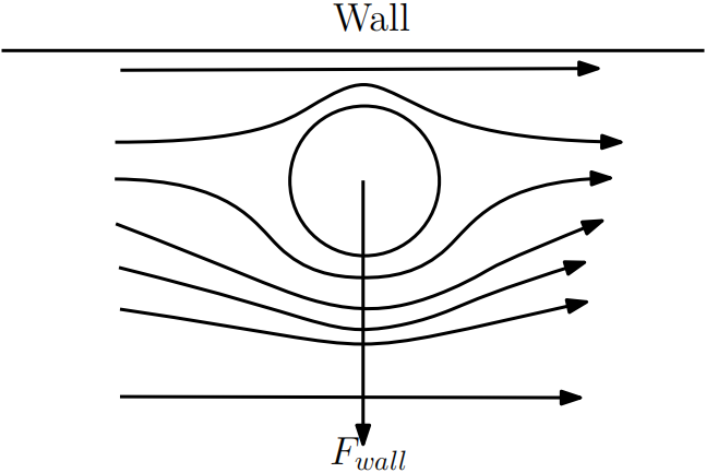
Figure 1. Flow being squeezed away from the wall generates a lift force away from the wall.
2. In the case where the flow profile is quadratic, the exact difference in velocity profile causes relative velocity difference as the particle flows with a mean velocity. The relative velocity on the side away from the wall is smaller than the relative velocity on the side close to the wall. This results in a pressure difference and a net force towards the wall for particles anywhere in the channel (Figure 2).
For a spherical object, an empirical equation is given [7]:
\( {F_{shear}}={C_{shear}}ρ{U^{2}}\frac{{d^{3}}}{{D^{4}}} \) (4)
where \( {C_{shear}} \) is an empirical dimensionless shear induced lift coefficient, whose magnitude depends strongly on the Reynolds number and particle’s radial position.
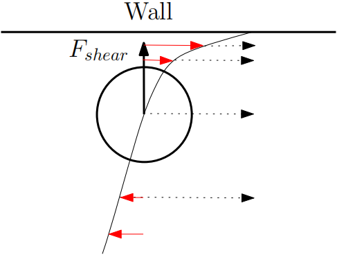
Figure 2. Quadratic velocity distribution leads to an inertial force towards the wall.
3. Computing the Equilibrium Lift Forces
In the first simulation experimental study, we aimed to investigate the effects of various factors on the lift coefficient of neutrally buoyant particles in a tubular Poiseuille flow. The particles of different sizes were placed at various radial distances from the center of the tube, while the longitudinal position was kept fixed at a downstream location. The lift coefficient was then calculated using openFOAM, a computational fluid dynamics solver. Details of the algorithm used is described in the Appendix: A section.
To facilitate the lift force simulations, we designed a setup with the geometry shown in Figures3 and 4. These figures provide a visual representation of the size, radial and longitudinal position of the particle relative to the tube. The size and radial position of the particle were varied between simulations to investigate their effects on the lift coefficient.
Our study provides valuable insights into the behavior of neutrally buoyant particles in Poiseuille flows, which have important applications in a variety of fields, including microfluidics and biomedicine. By gaining a deeper understanding of the lift forces acting on these particles, we can improve the design and efficiency of particle separation techniques, such as the Segre-Silberberg effect, and ultimately contribute to the development of more effective diagnostic and treatment methods for diseases such as cancer.
|
|
Figure 3. Position of the particle on the cross-sectional view of the tube. The empty circle off center is the position of the neutrally buoyant particle. | Figure 4. Position of the particle on the cross-sectional view of the tube. The empty circle off center is the position of the neutrally buoyant particle. |
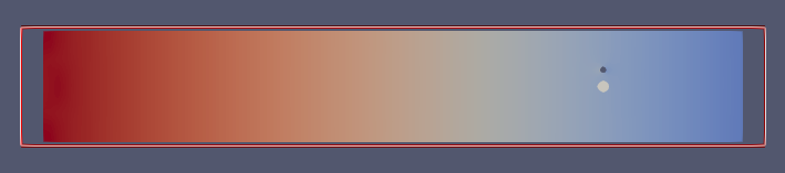
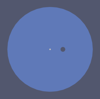
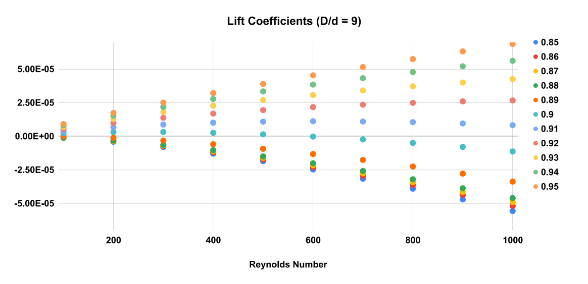
Figure 5. Equilibrium Position as a function of particle radial position and Reynolds number. As Reynolds number increases, the equilibrium position where lift coefficient becomes 0 moves towards the wall. D/d = 9.
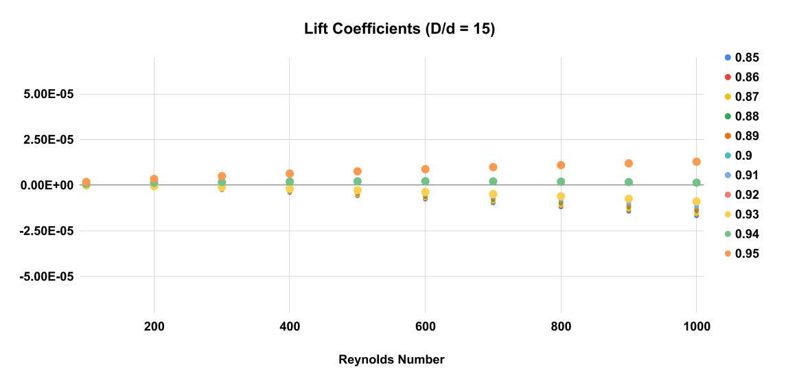
Figure 6. Equilibrium Position as a function of particle radial position and Reynolds number. As Reynolds number increases, the equilibrium position where lift coefficient becomes 0 moves towards the wall. D/d = 15.
The results of the numerical simulations indicate that the equilibrium position of the particles in the Poiseuille flow strongly depends on the Reynolds number and the particle diameter over channel diameter ratio. As shown in Figure 5, 6 and 7, the equilibrium position of the particles shifts towards the wall of the tube as the Reynolds number increases. At a low Reynolds number, the equilibrium position is closer to the center of the tube, but as the Reynolds number increases, the equilibrium position moves towards the wall of the tube.
For example, in Figures 5, 6 and 7 at a Reynolds number of 600, the equilibrium position for the larger particles ( \( D/d=9 \) ) is at 0.9 times the radius of the tube. At a higher Reynolds number of 800, the equilibrium position shifts slightly towards the wall of the tube to between 0.9 and 0.91 times the radius. For smaller particles ( \( D/d=15 \) ), the equilibrium position occurs at an even higher radial position closer to the wall of the tube.
These findings are important for the design of microfluidic devices that utilize the Segre-Silberberg effect for particle separation. By understanding how the equilibrium position of the particles varies with Reynolds number and particle size, researchers can optimize the design of microfluidic channels to achieve efficient and effective particle separation.
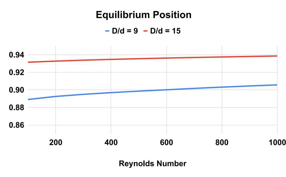
Figure 7. Equilibrium Position as a function of Reynolds number for the two different particle sizes. The greater the particle size, the further away the equilibrium position is from the wall.
4. Liquid Cancer Biopsy Application
To assess the effectiveness of the Segre-Silberberg effect in liquid cancer biopsy application, a customized 3D model was developed. The 3D model, shown in Figure8, was created using Blender [14], an open-source 3D graphics and animation software. The model features a straight inlet that leads to swirling sections near the outlet, which allow for concentration of streamlines and particle separation. The meshed 3D model used in openFOAM calculation, shown in Figure9, comprises 56, 000 cells to ensure accuracy in the simulations. The particle diameter used in the simulations was set to \( {10^{-5}} \) meters or \( 10 μm \) , which is like the diameter of breast cancer cells [15, 16]. The flow velocity was set to 5 m/s, and the diameter of the tube was \( 9×{10^{-5}} \) meters or \( 90 μm \) , resulting in a \( D/d \) ratio of exactly 9. This ratio was chosen because it is in the range that is commonly used for microfluidic devices [17]. The inlet flow velocity of 5 m/s results in a channel flow Reynolds number of 450, which is within the range where the Segre-Silberberg effect is observed [6].
The Multi-phase particle-in-cell (MPPIC) [18-20] numerical technique employed in this study combines Lagrangian and Eulerian methods to track the motion of cells in the flow. The method discretizes the continuous fluid and particle motion into a finite number of particles, and then solves the governing equations using a finite volume method. The particles interact with the continuous fluid through a momentum exchange algorithm, allowing for accurate simulation of the interaction between the cells and the fluid.
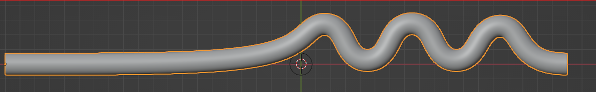
Figure 8. A customized design for the purpose for liquid cancer biopsy. The device has an initial straight section, then it’s twisted for the purpose of cell separation through Segre-Silberberg effect.
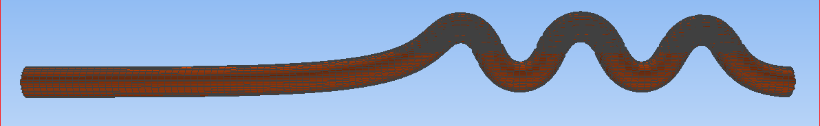
Figure 9. A meshed view of the device. Fluid and particles will come in from the left end of the device as shown in the figure.
The MPPIC method allows for a detailed examination of the migration of cells in the microfluidic device. By injecting cells into a static background flow field, the method enables the examination of how cells move under different flow conditions. While the method is not as accurate as an in-flow solver that tracks the dynamics and motion of each particle, it significantly improves the computational efficiency and is suitable for tracking large numbers of small particles in a mean flow. An in-flow solver that tracks each particle’s dynamics and motion is computationally prohibitive for many particles. The MPPIC method provides a good compromise between accuracy and computational cost, making it an effective tool for examining particle migration in microfluidic devices.
To evaluate the performance of the microfluidic device for liquid cancer biopsy, we injected cancer cells at the left end of the device at t = 0 and examined their migration behavior using the multi-phase particle-in-cell (MPPIC) numerical technique with openFOAM. The results showed that the background static flow was effective in separating the cancer cells from the mean flow, as seen in the second diagram in Figure10. The cancer cells were focused at specific positions in the channel, allowing for their efficient isolation and subsequent analysis for specific cancer markers or genetic mutations.
Overall, the design of the microfluidic device with its unique swirling sections near the outlet facilitated the concentration of streamlines, which helped to separate the cancer cells from the mean flow. The successful separation of cancer cells from a liquid biopsy using this microfluidic device has important implications for non-invasive and efficient cancer diagnosis and treatment.
|
|
|
|
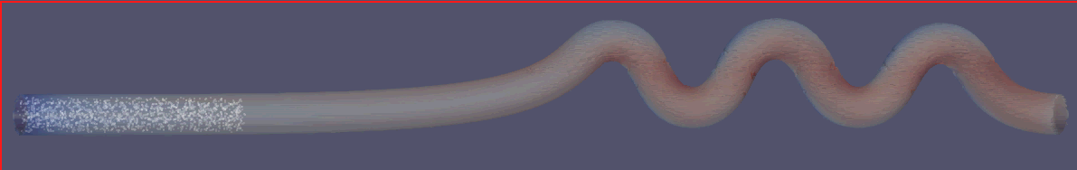
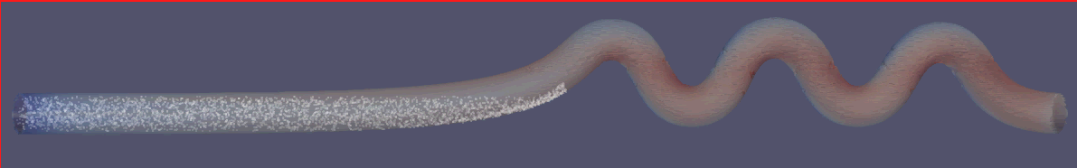
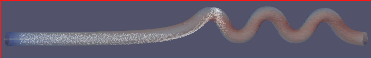
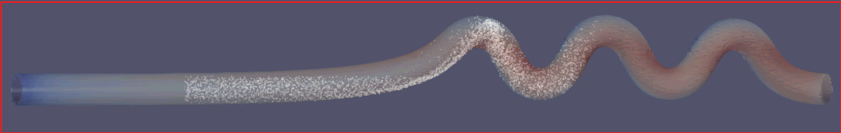
Figure 10. Injected cells flowing through the separation device.
The computer aided microfluidic design cycle allows us to rapidly prototype our design and test the design through CFD simulation. Conventional design and testing process involves the following steps [21]: 1) 3D design using a CAD software-based literature and previous attempts; 2) fabrication of the model through moulding; 3) preparing devices for test; 4) testing the devices using flow experiments. The entire process can take up to a week, although multiple designs and devices can be designed, fabricated, and tested at once. In contrast, computer aided design and test cycle can be done on a computer directly [22, 23] through the following steps: 1) 3D design using a CAD software-based literature and previous attempts; 2) Importing the 3D design in a CFD meshing software to prepare for fluid simulation tests. 3) Running CFD simulations with various parameters of particle size, flow velocity, mixing ratio. 4) Candidate designs will go through the fabrication, physical testing process for verification.
We primarily tested the following designs shown in Figure 11 and 12, the spiral design like what’s shown in Figure 12 is particularly popular in the microfluidics community [24-29]. Streamline and vorticities profiles in each design are examined.
The first design shown in Figure 11 is like what’s used in [26], we see strong streamline separation near the annulus position. No clear vorticity pattern is demonstrated by the design compared to that shown in Figure 11 although the vorticity values do grow to significant values near the wall as expected. Note that the vorticity field is not calculated directly by OpenFOAM solver but instead calculated using vector field on unstructured grid filter in Paraview [31]. This may explain the lack of clear and visible vorticity feature in the flow shown in Figure 11 and 12.
We then examined a design based on [25] in Figure 12. The streamlines are grouped closely near the exit on the outside of the design. Again, no clear vorticity patterns are observed. Comparing the results from the two designs we can see a stronger flow separation pattern in the first design compared to the popular spiral design. We also tested additional designs; they are shown in Figure 13 in Appendix: B. No strong separation effects are observed in the spiral designs.
5. Conclusion
In conclusion, we have successfully verified the Segre-Silberberg effect in a tubular flow through numerical simulations using openFOAM. We have shown that the equilibrium position where the net lift force becomes zero is a function of Reynolds number, particle size, and radial position (Figure 5, 6, and 7). Our results indicate that smaller particles and higher Reynolds numbers lead to the equilibrium position moving towards the wall of the tube.
Building upon the verification simulations, we have designed and tested a customized 3D device to investigate the potential for cancer cell separation in liquid biopsy. The device was modeled in Blender and meshed for use in openFOAM simulations. Our MPPIC simulations showed that upon entering the first bent section of the tube, cancer cells were successfully separated from the mean flow, providing evidence for the potential of our design for liquid biopsy applications.
The successful results of our simulations demonstrate the potential of computational fluid dynamics in the development and optimization of microfluidic devices for biomedical applications. The computer aided design process can provide faster and more economic approach to microfluidic design and fabrication. For the various designs we verified, we discover a lack of clear fluid separation pattern in spiral designs [25] compared to a simple branching design [30]. This may suggest Dean’s effect is likely not as strong as the Segre-Silberberg effect [5]. Our findings can contribute to the development of more efficient and effective liquid biopsy devices, ultimately leading to improved cancer detection and diagnosis. Further research can be conducted to optimize the design parameters and investigate the separation efficiency under varying flow conditions and particle properties.
While numerical simulation has the demonstrated advantages in evaluating and selecting potential designs, they are still far from a replacement for the assessment of the usefulness of a physical device. More fabrication of devices is needed, along with instrumentation to measure particle separation with particles that have a similar size to CTCs and blood cells in a fluid that has similar physical characteristics to blood.
|
|
|
|
|
|
| |
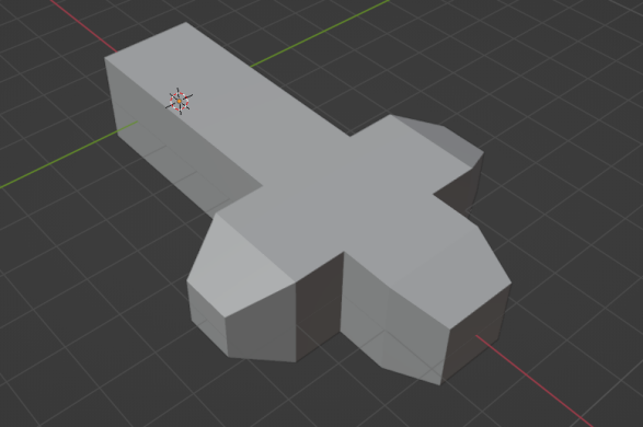
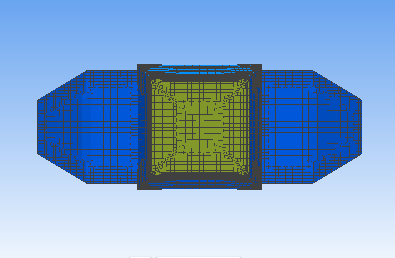
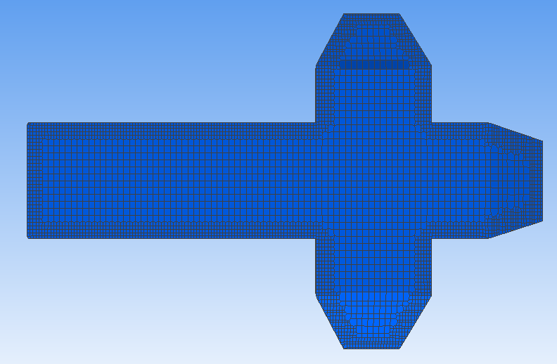
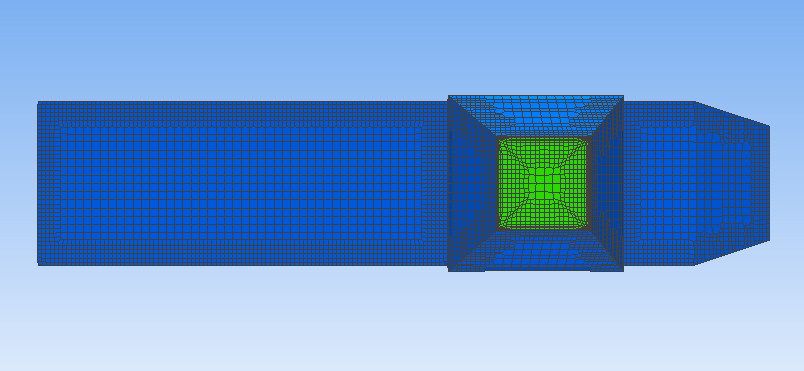
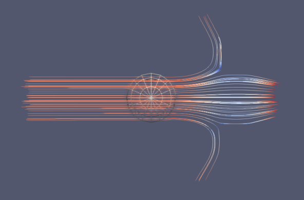
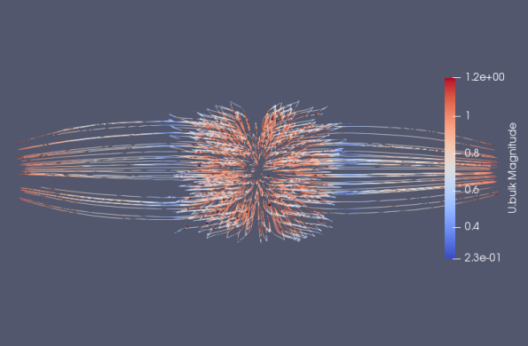
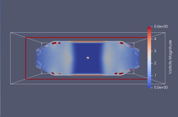
Figure 11. A design similar to [26]. From top left to bottom right, we have the 3D model designed in blender, meshed in simFlow, then the resulting streamline \( \frac{dx}{{v_{x}}}=\frac{dy}{{v_{y}}}=\frac{dz}{{v_{z}}} \) (top view and front view) and vorticity \( ∇×\vec{v} \) (front view) are analyzed. Fluid comes in from the inlet located near the longer segment of the device. There are three outlets each with a smaller area than the inlet. The outlets are located on the other end of the device.
|
|
|
|
|
|
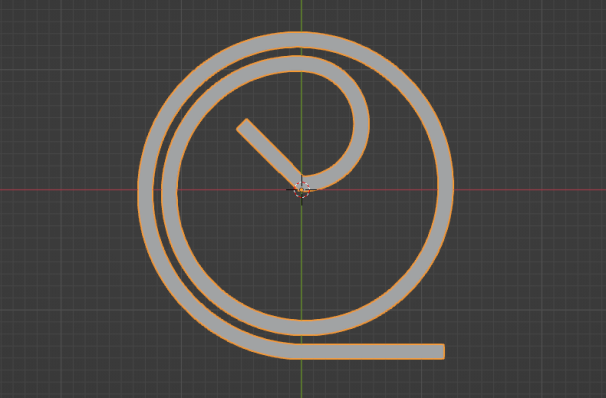
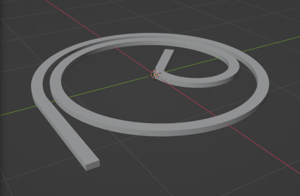
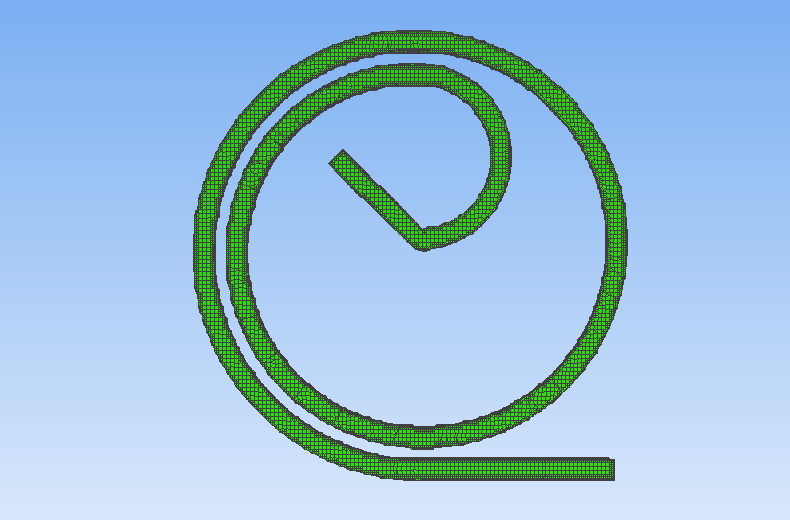

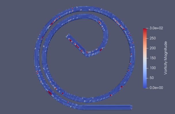
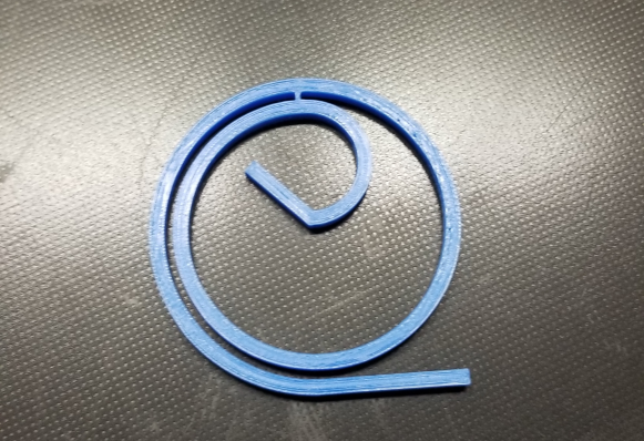
Figure 12. Spiral designs similar to [21]. From top left to bottom right, we have the 3D model designed in blender, meshed in simFlow, the resulting streamline (top view) and vorticity (top view) are analyzed, and finally a 3D printed microfluidic device fabricated for testing. The cross-sectional area of the device is rectangular to benefit from Dean’s effect [7]. Fluid comes in from the inlet located on the inside of the device. The outlets are located on the outside of the device.
Acknowledgments
I am very grateful for the support I received from my mentor, Dr. Fei Liu, who provided inspiration and guidance in this research work. I would also like to thank my parents for their continued support and encouragement.
References
[1]. R. L. Siege. Cancer statistics. CA Cancer J Clin, 73(1):17-48, 2023.
[2]. E. Crowley, F. Di Nicolantonio, F. Loupakis, and A. Bardelli. Liquid biopsy: monitoring cancer-genetics in the blood. Nature reviews Clinical oncology, 10(8), 472-484, 2013.
[3]. E. Lin, T. Cao, S. Nagrath, and M. R. King. Circulating tumor cells: diagnostic and therapeutic applications. Annual review of biomedical engineering, 20, 329-352, 2018.
[4]. S. N. Lone, S. Nisar, T Masoodi, M. Singh, A. Rizwan, S. Hashem, W. El-Rifai, and D. Bedognetti. Liquid biopsy: a step closer to transform diagnosis, prognosis and future of cancer treatments. Molecular Cancer, 21(1), 1-22, 2022.
[5]. G. Segré and A. Silberberg. Radial particle displacements in poiseuille flow of suspensions. Nature, 189(4760):209–210, 1961.
[6]. Jean-Philippe Matas, Jeffrey F. Morris, and Élisabeth Guazzelli. Inertial migration of rigid spherical particles in poiseuille flow. Journal of Fluid Mechanics, 515:171–195, 2004.
[7]. Dino DiCarlo, Daniel Irimia, Ronald G. Tompkins, and Mehmet Toner. Continuous inertial focusing, ordering, and separation of particles in microchannels. Proceedings of the National Academy of Sciences, 104(48):18892–18896, 2007.
[8]. Yusuke Morita, Tomoaki Itano, and Masako Sugihara-Seki. Equilibrium radial positions of neutrally buoyant spherical particles over the circular cross-section in poiseuille flow. Journal of Fluid Me- chanics, 813:750–767, 2017.
[9]. Antoine-Emmanuel Saliba, Laure Saias, Eleni Psychari, Nicolas Minc, Damien Simon, Francois- Clement Bidard, Claire Mathiot, Jean-Yves Pierga, Vincent Fraisier, Jean Salamero, VeroniqueSaada, Francoise Farace, Philippe Vielh, Laurent Malaquin, and Jean-Louis Viovy. Microfluidic sorting and multimodal typing of cancer cells in self-assembled magnetic arrays. Proceedings of the National Academy of Sciences, 107(33):14524–14529, 2010.
[10]. Schegoleva Bokova Larionova Denisov Tretyakova, Menyailo. Technologies for viable circulating tumor cell isolation. International Journal of Molecular Sciences, 23, 12 2022.
[11]. Ian Papautsky Nivedita Nivedita, Philip Ligrani. Dean flow dynamics in low-aspect ratio spiral mi- crochannels. Proceedings of the National Academy of Sciences, 2017.
[12]. H. Jasak C. Fureby H. G. Weller, G. Tabor. A tensorial approach to computational continuum mechanics using object-oriented techniques. COMPUTERS IN PHYSICS, 12(6).
[13]. George Keith Batchelor. An introduction to fluid dynamics. 2000.
[14]. Blender Online Community. Blender - a 3D modelling and rendering package. Blender Foundation, Stichting Blender Foundation, Amsterdam, 2018.
[15]. Vincent-Salomon A de Cremoux P Nos C et al. Pierga JY, Bonneton C. Clinical significance of immunocytochemical detection of tumor cells using digital microscopy in peripheral blood and bone marrow of breast cancer patients. Clin Cancer Res, 2004.
[16]. Simon P. Duffy Jenny Bazov Kim N. Chi Peter C. Black Sunyoung Park, Richard R. Ang and Hong- shen Ma. Morphological differences between circulating tumor cells from prostate cancer patients and cultured prostate cancer cells. PLOS ONE, 2014.
[17]. Doble M Sen AK. Sajeesh P, Manasi S. A microfluidic device with focusing and spacing control for resistance-based sorting of droplets and cells., 2015.
[18]. M.J. Andrews and P.J. O’Rourke. The multiphase particle-in-cell (mp-pic) method for dense particu- late flows. International Journal of Multiphase Flow, 22(2):379–402, 1996.
[19]. R.D. Braatz S.H. Kim, J.H. Lee. Multi-phase particle-in-cell coupled with population balance equa- tion (mp-pic-pbe) method for multiscale computational fluid dynamics simulation. Comput. Chem. Eng., 2020.
[20]. I. et al Cho. Numerical simulation method of a circulating fluidized bed reactor using a modified mp-pic solver of openfoam. Powder Technology, 409, 2022.
[21]. Wuchu D. Nagrath S. Nagrath Rupp, Ball. Circullating tumor cells in precision medicine: Challenges and opportunities. Trends in Pharmacological Sciences, 43, 03 2022.
[22]. Kulasinghe Arutha Bogseth Amanda O’Byrne Ken Punyadeera Chamindie Papautsky Ian Zhou, Jian. Isolation of circulating tumor cells in non-small-cell-lung-cancer patients using a multi-flow microflu- idic channel. Nature, 2019.
[23]. Jun Zhang, Sheng Yan, Dan Yuan, Gursel Alici, Nam-Trung Nguyen, Majid Ebrahimi Warkiani, and Weihua Li. Fundamentals and applications of inertial microfluidics: A review. Lab Chip, 16, 11 2015.
[24]. Yixing Gou, Jiawen Liu, Changku Sun, Zheng You, and DahaiRen. Inertial-assisted immunomagnetic bioplatform towards efficient enrichment of circulating tumor cells. Biosensors, 11:183, 06 2021.
[25]. Majid Ebrahimi Warkiani, Bee Luan Khoo, Lidan Wu, Andy Tay, Ali Asgar Bhagat, Jongyoon Han, and C.T. Lim. Ultra-fast, label-free isolation of circulating tumor cells from blood using spiral mi- crofluidics. Nature Protocols, 11:134–148, 12 2015.
[26]. Sudeepthi A. Sen A.K. Ajanth, P. Microfluidics technology for label-free isolation of circulating tumor cells. J. Inst. Eng. India, Ser. C 101, 1051–1071, 2020.
[27]. Jun-Jie Bai, Xuan Zhang, Xing Wei, Yu Wang, ChengDu, Ze-Jun Wang, Ming-Li Chen, and Jian-Hua Wang. Dean-flow-coupledelasto-inertial focusing accelerates exosome purification to facilitate single vesicle profiling. Analytical Chemistry, 95(4):2523–2531, 2023. PMID: 36657481.
[28]. Jongyoon Han A. Asgar, S. Bhagat. Dean flow fractionation (dff) isolation of circulating tumor cells (ctcs) from blood. Biology, 2011.
[29]. Dutta S. Nagahanumaiah et al. Mitra, P. Separation of particles in spiral micro-channel using dean’s flow fractionation. JBraz. Soc. Mech. Sci. Eng., 2020.
[30]. Corinne et al Renier. Label-free isolation of prostate circulating tumor cells using vortex microfluidic technology. Nature, 2017.
[31]. Berk Geveci James Ahrens and Charles Law. Visualization Handbook. Elesvier, 2005.
[32]. Hrvoje Jasak. Error analysis and estimation for the finite volume method with applications to fluid flows. Direct, M, 01 1996.
[33]. H. K. Versteeg and W. Malalasekera. An Introduction to Computational Fluid Dynamics: The Finite Volume Method. Longman Scientific and Technical, 1995.
[34]. J. H. Ferziger and M. Peric. Computational Methods for Fluid Dynamics. Springer, Berlin, 1996.
[35]. Weeratunge Malalasekera Henk Kaarle Versteeg. An Introduction to Computational Fluid Dynamics: The Finite Volume Method. 2007.
Cite this article
Recce,A. (2024). Improving liquid cancer biopsy through computer-aided microfluidic device design based on the tubular pinch effect and Dean’s flow. Theoretical and Natural Science,31,242-254.
Data availability
The datasets used and/or analyzed during the current study will be available from the authors upon reasonable request.
Disclaimer/Publisher's Note
The statements, opinions and data contained in all publications are solely those of the individual author(s) and contributor(s) and not of EWA Publishing and/or the editor(s). EWA Publishing and/or the editor(s) disclaim responsibility for any injury to people or property resulting from any ideas, methods, instructions or products referred to in the content.
About volume
Volume title: Proceedings of the 3rd International Conference on Computing Innovation and Applied Physics
© 2024 by the author(s). Licensee EWA Publishing, Oxford, UK. This article is an open access article distributed under the terms and
conditions of the Creative Commons Attribution (CC BY) license. Authors who
publish this series agree to the following terms:
1. Authors retain copyright and grant the series right of first publication with the work simultaneously licensed under a Creative Commons
Attribution License that allows others to share the work with an acknowledgment of the work's authorship and initial publication in this
series.
2. Authors are able to enter into separate, additional contractual arrangements for the non-exclusive distribution of the series's published
version of the work (e.g., post it to an institutional repository or publish it in a book), with an acknowledgment of its initial
publication in this series.
3. Authors are permitted and encouraged to post their work online (e.g., in institutional repositories or on their website) prior to and
during the submission process, as it can lead to productive exchanges, as well as earlier and greater citation of published work (See
Open access policy for details).
References
[1]. R. L. Siege. Cancer statistics. CA Cancer J Clin, 73(1):17-48, 2023.
[2]. E. Crowley, F. Di Nicolantonio, F. Loupakis, and A. Bardelli. Liquid biopsy: monitoring cancer-genetics in the blood. Nature reviews Clinical oncology, 10(8), 472-484, 2013.
[3]. E. Lin, T. Cao, S. Nagrath, and M. R. King. Circulating tumor cells: diagnostic and therapeutic applications. Annual review of biomedical engineering, 20, 329-352, 2018.
[4]. S. N. Lone, S. Nisar, T Masoodi, M. Singh, A. Rizwan, S. Hashem, W. El-Rifai, and D. Bedognetti. Liquid biopsy: a step closer to transform diagnosis, prognosis and future of cancer treatments. Molecular Cancer, 21(1), 1-22, 2022.
[5]. G. Segré and A. Silberberg. Radial particle displacements in poiseuille flow of suspensions. Nature, 189(4760):209–210, 1961.
[6]. Jean-Philippe Matas, Jeffrey F. Morris, and Élisabeth Guazzelli. Inertial migration of rigid spherical particles in poiseuille flow. Journal of Fluid Mechanics, 515:171–195, 2004.
[7]. Dino DiCarlo, Daniel Irimia, Ronald G. Tompkins, and Mehmet Toner. Continuous inertial focusing, ordering, and separation of particles in microchannels. Proceedings of the National Academy of Sciences, 104(48):18892–18896, 2007.
[8]. Yusuke Morita, Tomoaki Itano, and Masako Sugihara-Seki. Equilibrium radial positions of neutrally buoyant spherical particles over the circular cross-section in poiseuille flow. Journal of Fluid Me- chanics, 813:750–767, 2017.
[9]. Antoine-Emmanuel Saliba, Laure Saias, Eleni Psychari, Nicolas Minc, Damien Simon, Francois- Clement Bidard, Claire Mathiot, Jean-Yves Pierga, Vincent Fraisier, Jean Salamero, VeroniqueSaada, Francoise Farace, Philippe Vielh, Laurent Malaquin, and Jean-Louis Viovy. Microfluidic sorting and multimodal typing of cancer cells in self-assembled magnetic arrays. Proceedings of the National Academy of Sciences, 107(33):14524–14529, 2010.
[10]. Schegoleva Bokova Larionova Denisov Tretyakova, Menyailo. Technologies for viable circulating tumor cell isolation. International Journal of Molecular Sciences, 23, 12 2022.
[11]. Ian Papautsky Nivedita Nivedita, Philip Ligrani. Dean flow dynamics in low-aspect ratio spiral mi- crochannels. Proceedings of the National Academy of Sciences, 2017.
[12]. H. Jasak C. Fureby H. G. Weller, G. Tabor. A tensorial approach to computational continuum mechanics using object-oriented techniques. COMPUTERS IN PHYSICS, 12(6).
[13]. George Keith Batchelor. An introduction to fluid dynamics. 2000.
[14]. Blender Online Community. Blender - a 3D modelling and rendering package. Blender Foundation, Stichting Blender Foundation, Amsterdam, 2018.
[15]. Vincent-Salomon A de Cremoux P Nos C et al. Pierga JY, Bonneton C. Clinical significance of immunocytochemical detection of tumor cells using digital microscopy in peripheral blood and bone marrow of breast cancer patients. Clin Cancer Res, 2004.
[16]. Simon P. Duffy Jenny Bazov Kim N. Chi Peter C. Black Sunyoung Park, Richard R. Ang and Hong- shen Ma. Morphological differences between circulating tumor cells from prostate cancer patients and cultured prostate cancer cells. PLOS ONE, 2014.
[17]. Doble M Sen AK. Sajeesh P, Manasi S. A microfluidic device with focusing and spacing control for resistance-based sorting of droplets and cells., 2015.
[18]. M.J. Andrews and P.J. O’Rourke. The multiphase particle-in-cell (mp-pic) method for dense particu- late flows. International Journal of Multiphase Flow, 22(2):379–402, 1996.
[19]. R.D. Braatz S.H. Kim, J.H. Lee. Multi-phase particle-in-cell coupled with population balance equa- tion (mp-pic-pbe) method for multiscale computational fluid dynamics simulation. Comput. Chem. Eng., 2020.
[20]. I. et al Cho. Numerical simulation method of a circulating fluidized bed reactor using a modified mp-pic solver of openfoam. Powder Technology, 409, 2022.
[21]. Wuchu D. Nagrath S. Nagrath Rupp, Ball. Circullating tumor cells in precision medicine: Challenges and opportunities. Trends in Pharmacological Sciences, 43, 03 2022.
[22]. Kulasinghe Arutha Bogseth Amanda O’Byrne Ken Punyadeera Chamindie Papautsky Ian Zhou, Jian. Isolation of circulating tumor cells in non-small-cell-lung-cancer patients using a multi-flow microflu- idic channel. Nature, 2019.
[23]. Jun Zhang, Sheng Yan, Dan Yuan, Gursel Alici, Nam-Trung Nguyen, Majid Ebrahimi Warkiani, and Weihua Li. Fundamentals and applications of inertial microfluidics: A review. Lab Chip, 16, 11 2015.
[24]. Yixing Gou, Jiawen Liu, Changku Sun, Zheng You, and DahaiRen. Inertial-assisted immunomagnetic bioplatform towards efficient enrichment of circulating tumor cells. Biosensors, 11:183, 06 2021.
[25]. Majid Ebrahimi Warkiani, Bee Luan Khoo, Lidan Wu, Andy Tay, Ali Asgar Bhagat, Jongyoon Han, and C.T. Lim. Ultra-fast, label-free isolation of circulating tumor cells from blood using spiral mi- crofluidics. Nature Protocols, 11:134–148, 12 2015.
[26]. Sudeepthi A. Sen A.K. Ajanth, P. Microfluidics technology for label-free isolation of circulating tumor cells. J. Inst. Eng. India, Ser. C 101, 1051–1071, 2020.
[27]. Jun-Jie Bai, Xuan Zhang, Xing Wei, Yu Wang, ChengDu, Ze-Jun Wang, Ming-Li Chen, and Jian-Hua Wang. Dean-flow-coupledelasto-inertial focusing accelerates exosome purification to facilitate single vesicle profiling. Analytical Chemistry, 95(4):2523–2531, 2023. PMID: 36657481.
[28]. Jongyoon Han A. Asgar, S. Bhagat. Dean flow fractionation (dff) isolation of circulating tumor cells (ctcs) from blood. Biology, 2011.
[29]. Dutta S. Nagahanumaiah et al. Mitra, P. Separation of particles in spiral micro-channel using dean’s flow fractionation. JBraz. Soc. Mech. Sci. Eng., 2020.
[30]. Corinne et al Renier. Label-free isolation of prostate circulating tumor cells using vortex microfluidic technology. Nature, 2017.
[31]. Berk Geveci James Ahrens and Charles Law. Visualization Handbook. Elesvier, 2005.
[32]. Hrvoje Jasak. Error analysis and estimation for the finite volume method with applications to fluid flows. Direct, M, 01 1996.
[33]. H. K. Versteeg and W. Malalasekera. An Introduction to Computational Fluid Dynamics: The Finite Volume Method. Longman Scientific and Technical, 1995.
[34]. J. H. Ferziger and M. Peric. Computational Methods for Fluid Dynamics. Springer, Berlin, 1996.
[35]. Weeratunge Malalasekera Henk Kaarle Versteeg. An Introduction to Computational Fluid Dynamics: The Finite Volume Method. 2007.