


1. Introduction
Due to its characteristics such as high energy, good coherence, and excellent monochromaticity, lasers have been widely used in laser communication, laser ranging, laser cutting, laser interference, and spatial optics. However, the large difference in divergence angles between perpendicular directions and the inherent astigmatism of semiconductor lasers result in low optical utilization efficiency and poor coupling efficiency. Therefore, it is necessary to collimate and shape the divergent beam of the laser. Long-distance underwater laser communication imposes high requirements on the collimation and circularity of the laser beam. Currently, domestic and international collimation shaping methods include: 1) a diffraction scheme with step-shaped surface, which achieves a 2.8-fold expansion of the Gaussian beam, but this approximate non-spherical component involves complex calculations, intricate manufacturing processes, and difficult-to-achieve processing accuracy. [1] 2) Utilizing a scheme of collimation with dual-focal-length micro-lenses, the divergent angles after collimation are 11.2° for the fast axis and 4.6° for the slow axis, with a large difference between the divergent angles of the fast and slow axes and they are not close. [2] 3) Using a combination of non-spherical and cylindrical mirrors, the system consists of four lenses in total, with a total length too long, and the divergence angle of collimation shaping is large, with a tested propagation distance of only 1 meter. [3] Therefore, designing a laser shaping and collimating system with small divergence angles, similar divergent angles for the fast and slow axes, shorter barrel length, easy processing and adjustment, and suitable for underwater coarse tracking and precise alignment, is of great significance.
2. Design Principles and Parameter Determination
2.1. Design Principles
Due to the thin active layer and asymmetric cross-section structure of edge-emitting semiconductor lasers, they exhibit a large divergence angle. The divergence angle in the fast axis direction is nearly 50°, while in the slow axis direction, it is around 10°. For semiconductor lasers, both the fast and slow axis directions follow Gaussian distributions [2], and the divergence angles in the vertical direction are different, resulting in different spot sizes. Due to astigmatism, the waist positions in the fast and slow axis directions are also inconsistent. As shown in Figure 1.
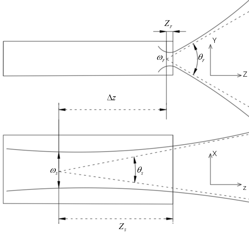
Figure 1. Characteristics of the Beam of Semiconductor Lasers
The waist of the fast axis direction ( \( {ω_{F}} \) ) is located near the laser emitting surface, while the waist of the slow axis direction ( \( {ω_{S}} \) ) is within the laser cavity. The distance between the waists in the fast and slow axes is the intrinsic astigmatism ( \( Δz \) ). The divergence angles of the laser beam in the fast ( \( Y \) ) and slow ( \( X \) ) axis directions are significantly different, resulting in an elliptical far-field spot. To achieve shaping and collimation of the semiconductor laser beam, two cylindrical lenses are combined, with their normals perpendicular to each other, each lens collimating the beam in the fast and slow axis directions, respectively. Collimation achieved using two mutually perpendicular cylindrical lenses results in residual divergence angle. In practice, precise calibration and fixation of the relative positions of the collimating lenses for the fast and slow axes are required, with a small tolerance, leading to larger residual divergence angles. [4] Therefore, firstly, the laser beam needs to be shaped to make the divergence angles of the fast and slow axes close to each other. Secondly, based on the principle of afocal zooming, a laser collimation zoom system is designed, with an adjustable beam expansion ratio of 2-10, facilitating APT (Acousto-Optic Tracking). Under different magnifications, the maximum wavefront error (RMS) of the collimation zoom system is 0.2 \( λ \) , all less than \( λ \) /4, meeting the requirements for aberration evaluation. By combining the collimating lenses for the fast and slow axes with the zooming beam expander, the final divergence angle for underwater propagation can be met, and precise coarse tracking and fine alignment underwater can be achieved by adjusting the magnification of the beam expander. Adjusting the magnification of the beam expander can also reduce the difficulty of processing and adjustment while meeting the same requirements. Directly expanding and collimating the semiconductor laser beam would reduce the uniformity of the beam, leading to significant energy loss and seriously affecting the detection results of underwater laser communication.
2.2. Parameter Determination
This paper designs an optical antenna based on semiconductor lasers to achieve long-distance, high-speed underwater data communication by combining shaping and collimating the fast and slow axes with beam expansion and collimation. Figure 2 depicts the symmetric underwater optical antenna system. The semiconductor laser beam passes through shaping and collimation of the fast and slow axes, then through an optical isolator and a beam splitter, and propagates in a 100-meter underwater channel after beam expansion and collimation. Subsequently, the beam enters the receiving antenna, where the reflected light reaches the CCD for stable and effective capture, aiming, and tracking of the communication laser beam, while the transmitted light focuses on the sensitive surface of the avalanche photodiode for signal transmission.
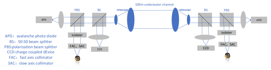
Figure 2. Symmetrical Underwater Optical Antenna System
Since the transmission loss of blue-green light with a wavelength of 450-550 nm is lowest in seawater, this paper chooses the PL450B semiconductor laser produced by Osram, with a main wavelength of 447 nm and a laser output power of 5 W. The vertical beam divergence angle is 49°, and the parallel beam divergence angle is 9°. The detector selected is the APD130A2 avalanche photodiode produced by Thorlabs, with a sensitivity range of 200-1000 nm and a photosensitive surface diameter of 1mm. The overall dimensions of the optical antenna must not exceed 350 mm × 250 mm × 150 mm, which facilitates the implementation of the capture, aim, and tracking system on the platform.
3. Simulation and Design
3.1. Shaping of Fast and Slow Axes
The preliminary shaping and collimation of the semiconductor laser beam utilize two cylindrical lenses with normals perpendicular to each other to shape the beams in the fast and slow axis directions, respectively. Initially, in sequential mode, the size and position of the entrance pupil are determined using the vignetting coefficient, with parameters VCX/VCY/VDX/VDY/VAN representing scaling, offset, and angular relationships. Given that the vertical divergence angle of the laser beam is 49° and the parallel divergence angle is 9°, the vignetting parameter, \( VCX=1-tan{(}4.{5^{°}})/(24.{5^{°}}) \) , is set to 0.8273. The size of the entrance pupil is set to \( sin{(}θ/2) \) , where \( θ \) represents the divergence angle in the direction requiring collimation for the laser. Using two Toroidal surfaces to simulate cylindrical lenses allows parallel light beams to converge into a straight line along the meridian (along the Y-axis direction), while sagittal rays (along the X-axis direction) remain unchanged.
The equation for the Toroidal surface is given by:
\( z=\frac{c{y^{2}}}{1+\sqrt[]{1-(1+k){c^{2}}{y^{2}}}}+{a_{1}}{y^{2}}+{a_{2}}{y^{4}}+{a_{3}}{y^{6}}+{a_{4}}{y^{8}}+{a_{5}}{y^{10}}+{a_{6}}{y^{12}}+{a_{7}}{y^{14}}\ \ \ (1) \)
Establish a cylindrical lens with a plane in the X direction, where y is the coordinate variable, c is the reciprocal of the radius of curvature, a represents the coefficients of variable orders, and k represents the conic coefficient of the equation. Similarly, establish a cylindrical lens with a plane in the Y direction, with the same equation, obtained by tilting 90 degrees.
Table 1 shows the initial structural parameters of the cylindrical lens. Finally, examining the point diagram, the size of the speckle approaches the diffraction limit.
Table 1. Initial Structural Parameters of the Cylindrical Lens
Surface | Radius/mm | Thickness/mm | material |
Object | Infinity | 3 | — |
Toroidal | Infinity | 5 | BK7 |
Toroidal | -5 | 10 | — |
Image | Infinity | — | — |
Using this method to design cylindrical lenses to correct the fast and slow axes, transitioning to non-sequential mode requires the addition of a light source and a detection surface. The normals of the two cylindrical lenses are perpendicular to each other, with the tilt Z parameter of the fast axis collimator set to 0° and the tilt Z parameter of the slow axis collimator set to 90°. Adding a detector to observe the outgoing light spot. Figure 3 shows the collimation of the semiconductor laser beam through the fast and slow axis collimators in two orthogonal directions.
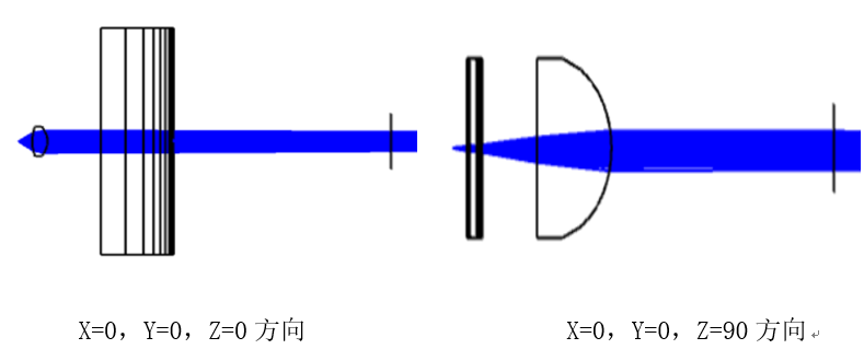
Figure 3. Collimation of the Fast and Slow Axes of the Semiconductor Laser
The detector is placed 50 mm behind the fast and slow axis collimators, as shown in Figure 4. From the figure, it can be seen that using the fast and slow axis collimating mirrors can initially achieve divergence angle compression and improve the roundness. By observing the detector at distances of 1 m and 2 m from the light source, the following values are obtained for the light spot radii in the x-direction: \( {R_{x1}} \) =4.54 mm, \( {R_{x2}} \) =5.80 mm, and in the y-direction: \( {R_{y1}} \) =5.61 mm, \( {R_{y2}} \) =6.85 mm. Calculating, the half divergence angle of the slow axis is \( arctan{(}({R_{x2}}-{R_{x1}})/({z_{2}}-{z_{1}})) \) = 1.26 mrad, and the fast axis is \( arctan{(}({R_{y2}}-{R_{y1}})/({z_{2}}-{z_{1}})) \) = 1.24 mrad. Due to project requirements, the divergence angle of the transmitting antenna needs to be less than 0.25 mrad, so further divergence angle compression is required using a beam expander.
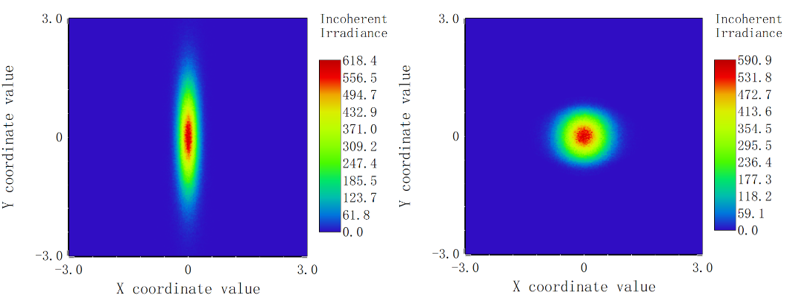
Figure 4. Comparison of Detectors before and after Laser Shaping and Collimation
3.2. Design of Beam Expander System
From the Gaussian characteristics of the semiconductor laser, it is known that the divergence angle is inversely proportional to the waist radius of the beam:
\( θ=\frac{2λ}{π{ω_{0}}}\ \ \ (2) \)
where: \( λ \) is the incident wavelength; \( {ω_{0}} \) is the waist radius of the Gaussian beam; \( θ \) is the divergence angle.
After passing through the beam expander system, the output beam waist diameter is larger than the input beam waist diameter, and the output divergence angle is smaller than the input divergence angle. The magnification factor M can be expressed in terms of the input and output divergence angles or the beam waist diameters:
\( M=\frac{{ω_{1}}}{{ω_{0}}}, M=\frac{{θ_{i}}}{{θ_{0}}}\ \ \ (3) \)
where: \( {θ_{i}} \) is the input beam divergence angle, \( {θ_{0}} \) is the output beam divergence angle; \( {ω_{0}} \) is the input beam spot diameter, \( {ω_{1}} \) is the output beam spot diameter.
The beam expander system is mainly divided into reflective and transmissive types. Transmissive systems are easy to correct for aberrations, have lower optical energy loss, simple structure, and easy processing and assembly. Reflective systems have no chromatic aberration, lower absorption loss, and shorter tube lengths at higher magnifications. However, processing off-axis parabolic surfaces is difficult, and adjustment is complex. Therefore, a transmissive beam expander system is adopted. After the semiconductor laser beam passes through the fast and slow axis collimators, it reaches the beam expander through the optical isolator and beam splitter. A distance of 50 mm is reserved for the optical isolator and beam splitter. Figure 5 shows the image on the detector 50 mm behind the fast and slow axis collimators, with a spot diameter smaller than 3mm. The entrance pupil diameter of the beam expander is taken as 3 mm.
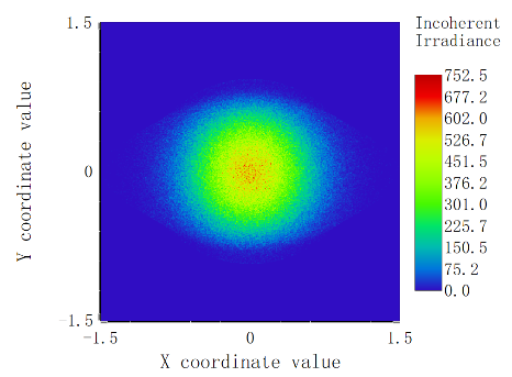
Figure 5. Image on the Detector 50mm behind the Fast and Slow Axes
In ZEMAX, input the initial structure as shown in Table 2. At this point, the system’s tube length is 90mm, and the magnification factor is 5. According to the magnification formula, the divergence angles of the beam in the fast and slow axis directions after expansion are 0.496 mrad and 0.504 mrad, respectively, which do not meet the collimation requirements. Therefore, it is necessary to scale the initial structure by scaling the distance from the object surface to the image surface to 160 mm, modifying the aperture size and field of view, and changing the type of vignetting to Gaussian distribution with a vignetting factor of 1. Add the optimization wizard in ZEMAX, choose wavefront optimization for image quality, Gaussian quadrature for pupil sampling, use the operand TTHI to extract the system length, the operand OPLT to control the system length not exceeding 160mm, the operand REAY to control the output beam radius to ensure the magnification factor, and use the operand EFLY to extract the focal length, and DIVI for division to control the magnification factor.
Table 2. Initial Structural Parameters of the Beam Expander System
Surface | Radius/mm | Thickness/mm | material | Semi-Dia/mm |
object | Infinity | Infinity | — | 0 |
stop | Infinity | 12.7 | — | 0.508 |
standard | -8.745 | 0.762 | SF8 | 2.540 |
standard | Infinity | 48.641 | — | 2.540 |
standard | Infinity | 3.353 | SF8 | 8.890 |
standard | -43.716 | 25.4 | — | 8.890 |
image | Infinity | — | — | 7.531 |
The initial structure of the beam expander system consists of two sets of lenses. After optimization of the imaging system, two pieces of double-bonded lenses are used instead of the original single set of lenses to improve imaging quality. Due to the high energy of the laser beam, damage may occur to the bonded surface. Therefore, the double-bonded lenses are designed as a double-separation structure, using glass replacement and air gaps to increase variable correction of aberrations. After further optimization, a three-piece spherical optical structure is formed, as shown in Figure 6. Considering factors such as system size, magnification factor, point diagram, and distribution of light rays, the magnification factor of the beam expander is ultimately determined to be 10.
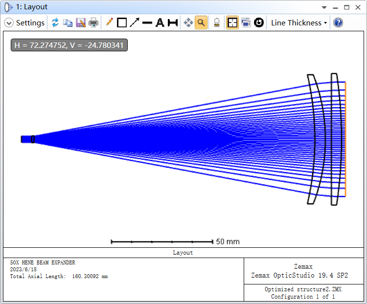
Figure 6. Three-piece Beam Expander System
As shown in Figure 7, the wavefront RMS of the beam expander system is 0.0106 wavelengths, and the peak-to-valley distance is 0.0584 wavelengths. From the ray trace diagram, it can be observed that the outgoing beam diameter is 53.933 mm, and at a distance of 100 meters, the spot size is 56 mm. The beam divergence is small, indicating perfect imaging, meeting the requirements of the system.
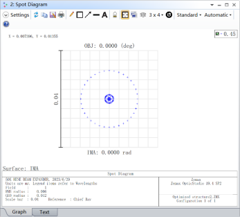
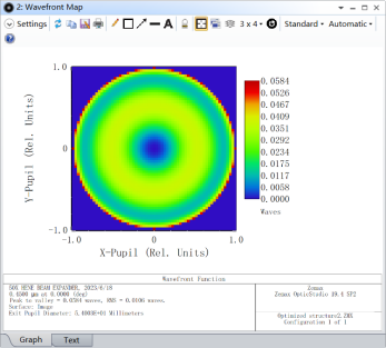
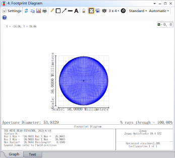
Figure 7. Point Diagram, Wavefront Map, and Ray Trace Diagram at the Image Plane 100 Meters away
According to the literature, the zoom system is composed of three lens groups: the front fixed group, the zoom group, and the compensation group. [5] The first lens group moves linearly as the zoom group, the second lens group moves synchronously as the compensation group, while maintaining the image plane stationary. This requirement ensures that under the condition of a stationary image plane, aberrations are simultaneously corrected with a series of different object planes. When using three lens groups, forms such as “positive-negative-positive”, “negative-positive-negative”, or “negative-negative-positive” can be adopted. The system structure is as shown in the diagram: where \( {L_{1}} \) is the front fixed group; \( {L_{2}} \) is the zoom group; and \( {L_{3}} \) is the compensation group.
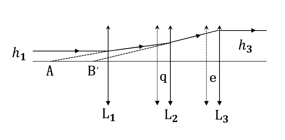
Figure 8. Principle Diagram of the Afocal Zoom Beam Expander System
From the diagram, point A is the image point of the front fixed group \( {L_{1}} \) and the object point of the zoom group \( {L_{2}} \) ; point B is the image point of the zoom group \( {L_{2}} \) and also the object point of the compensation group \( {L_{3}} \) . Assuming the amount of movement of the zoom group \( {L_{2}} \) is q, and the amount of movement of the compensation group \( {L_{3}} \) is e, when the system is a no-focus system, the magnification factor of the zoom group \( {L_{2}} \) in the meridional axis is:
\( {m_{2}}(q)=-\frac{{f_{2}}}{x}=-\frac{f_{2}^{ \prime }}{-f_{1}^{ \prime }+{d_{1}}+q-f_{2}^{ \prime }}=\frac{f_{2}^{ \prime }}{f_{1}^{ \prime }+f_{2}^{ \prime }-({d_{1}}+q)}\ \ \ (4) \)
The relationship between the object and image of the zoom group \( {L_{2}} \) can be obtained as:
\( \frac{1}{-[f_{3}^{ \prime }-e-({d_{2}}-q)]}-\frac{1}{-(-f_{1}^{ \prime }+{d_{1}}+q)}=\frac{1}{f_{2}^{ \prime }}\ \ \ (5) \)
The movement amount of the compensation group \( {L_{2}} \) is as follows:
\( e=\frac{f_{1}^{ \prime }f_{2}^{ \prime }-({d_{1}}+q)f_{2}^{ \prime }}{f_{1}^{ \prime }+f_{2}^{ \prime }-({d_{1}}+q)}+f_{3}^{ \prime }-{d_{2}}+q\ \ \ (6) \)
Let the radius of the entering light be \( {h_{1}} \) , and the radius of the outgoing light be \( {h_{3}} \) , then:
\( \begin{cases}\begin{matrix}{h_{1}}=(-f_{1}^{ \prime })tan{(-u)}=f_{1}^{ \prime }tan{u} \\ {h_{3}}=f_{3}^{ \prime }tan{(-{u^{ \prime }})}=-f_{3}^{ \prime }tan{{u^{ \prime }}} \\ \frac{tan{{u^{ \prime }}}}{tan{u}}=\frac{1}{{m_{2}}(q)} \\ \end{matrix}\end{cases}\ \ \ (7) \)
Where \( u \) is the aperture angle in the object space of the zoom group \( {L_{2}} \) , and \( {u^{ \prime }} \) is the aperture angle in the image space of the zoom group \( {L_{2}} \) .
The magnification factor M is:
\( M=\frac{{h_{3}}}{{h_{1}}}=-\frac{f_{3}^{ \prime }}{f_{1}^{ \prime }{m_{2}}(q)}\ \ \ (8) \)
This provides the relationship between the movement of the zoom group \( {L_{2}} \) and the compensation group \( {L_{3}} \) relative to the front fixed group \( {L_{1}} \) . If \( f_{1}^{ \prime }、f_{2}^{ \prime }、f_{3}^{ \prime }、{d_{1}}、{d_{2}} \) are known, the required beam expansion ratio M can be substituted into Equation (5) to obtain \( {m_{2}}(q) \) ; then \( {m_{2}}(q) \) can be substituted into Equation (1) to obtain the movement amount q of the zoom group \( {L_{2}} \) ; finally, q value can be substituted into Equation (3) to obtain the movement amount e of the compensation group \( {L_{3}} \) . When the beam expansion ratio changes, repeat the above process to obtain the movement amount of the zoom group \( {L_{2}} \) and the compensation group \( {L_{3}} \) relative to the front fixed group \( {L_{1}} \) , thereby designing a laser zoom collimation and beam expansion system that meets the zoom ratio.
The parameter indicators of the laser zoom collimation and beam expansion system are set as follows:
Laser wavelength: \( λ \) =447 nm, incident laser beam diameter: D=3 mm, system magnification: adjustable from 2 to 10 times continuously. The initial structure is selected, and based on the existing lenses in the laboratory, the above formula is used to calculate the relative displacement of the zoom group \( {L_{2}} \) and the compensating group \( {L_{3}} \) with respect to the front fixed group \( {L_{1}} \) , given that \( f_{1}^{ \prime }、f_{2}^{ \prime }、f_{3}^{ \prime }、{d_{1}}、{d_{2}} \) are known. Through continuous optimization, the final design of the lens data is obtained, as shown in Figure 9.
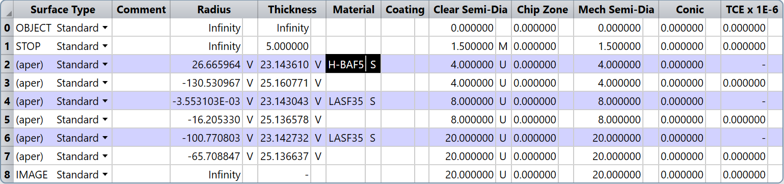
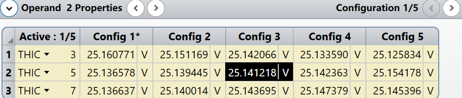
Figure 9. Data of the Laser Zoom Collimation and Beam Expansion System
As the laser zoom beam expander system belongs to a small aberration system, wave aberration is chosen as the evaluation criterion. The wave aberration at each magnification ratio is shown in Figure 10.
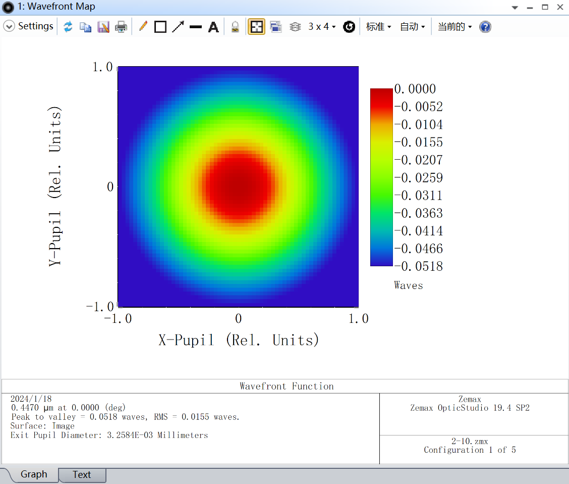
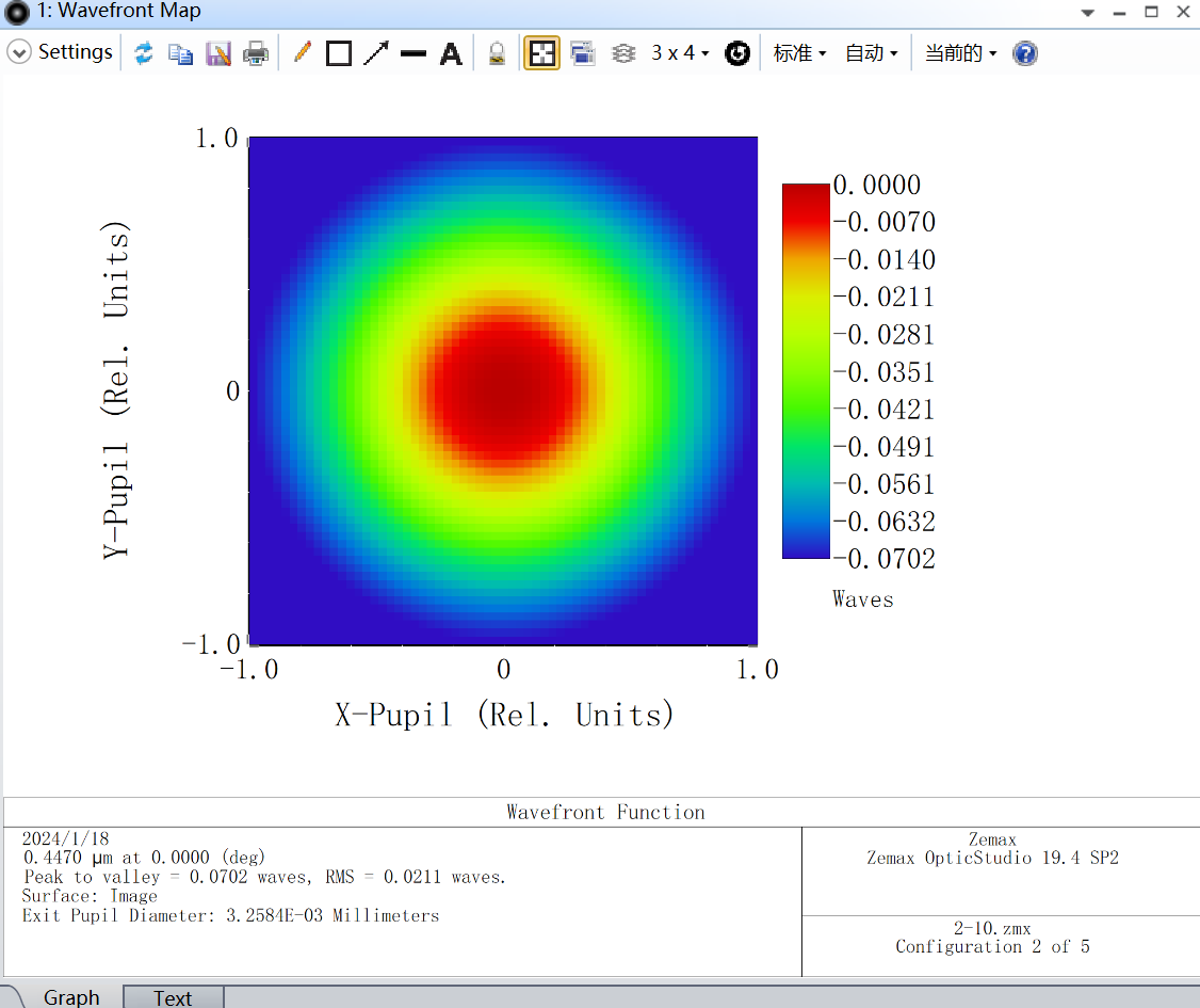
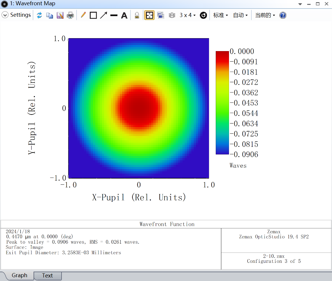
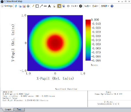
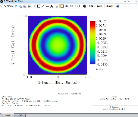
Figure 10. Wavefront Map Data of the Beam Expander at 2-10 Times Magnification.
Using Zemax for tolerance analysis, the refractive index, aberration error, irregularity, aperture, thickness, eccentricity, and allowable tilt errors of the optical components are provided. A Monte Carlo method is employed to randomly analyze 50 lenses, selecting the Root-Mean-Square (RMS) angular radius as the structural evaluation standard. It is found that 90% of the lenses have an RMS Y-directional angular radius less than 7.58×10⁻⁵, and 80% of the lenses have a Y-directional RMS angular radius less than 6.46×10⁻⁵. The results indicate that the collimation accuracy of the beam expander lenses meets the system requirements.
3.3. Overall Simulation
In sequential mode, the parameters of the designed Galilean beam expander are copied to the fast and slow axis collimator lens and then converted to non-sequential mode. Semiconductor laser parameters are added, and detection surfaces at different distances are included to perform ray tracing on the overall shaping and beam expansion system. The overall optical system is depicted in Figure 11.
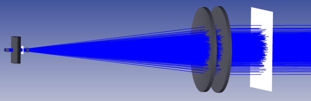
Figure 11. Beam Shaping System
The detector is set at a distance of 100 meters from the beam expander system. By opening the detector viewer, the text interface displays a beam diameter of 17.50 mm in the y-direction and 18.40 mm in the x-direction. Since the 100-meter distance is in the far-field distribution, dividing the beam diameter by the distance yields a fast-axis divergence angle of 0.175mrad and a slow-axis divergence angle of 0.184mrad. The total optical power on the receiving surface is 4.636 W, with an optical utilization efficiency of 92.72%.
A shaping beam expander system with reversed configuration is set up at a distance of 100 meters to form a symmetrical optical antenna. Simultaneously, the optical power is focused on the APD detector using a focusing lens, resulting in a simulated receiving power of 4.345 W. By axially adjusting the distance between the fast and slow axes, the relationship between axial error and power attenuation is obtained, as shown in Table 4. The results indicate that within a ±20μm error range, the power attenuation of the APD detector is <3.9%.
Table 4. Relationship between Fast and Slow Axis Axial Error and Power
Fast axis/mm | -0.02 | -0.01 | 0 | +0.01 | +0.02 |
Power/w | 4.176 | 4.339 | 4.345 | 4.336 | 4.228 |
Slow axis/mm | -0.02 | -0.01 | 0 | +0.01 | +0.02 |
Power/w | 4.344 | 4.345 | 4.345 | 4.345 | 4.345 |
4. Experimental Analysis
4.1. Optical Antenna Divergence Angle
Figure 12 illustrates the actual setup of the optical antenna testing apparatus after adjustment. The main components include the Osram semiconductor laser 450LB, machined cylindrical lenses, a 10x Galilean beam expander, and a cage system. The resolution of the setup is 1600 (H) × 1200 (V) pixels, with a pixel size of 4.5 μm × 4.5 μm CMOS sensor. Due to experimental constraints, a clean and transparent water tank is used to simulate underwater conditions, with dimensions of 2 m (length) × 0.2 m (width) × 0.1 m (height). The water quality is clear, meeting the requirements for underwater communication.
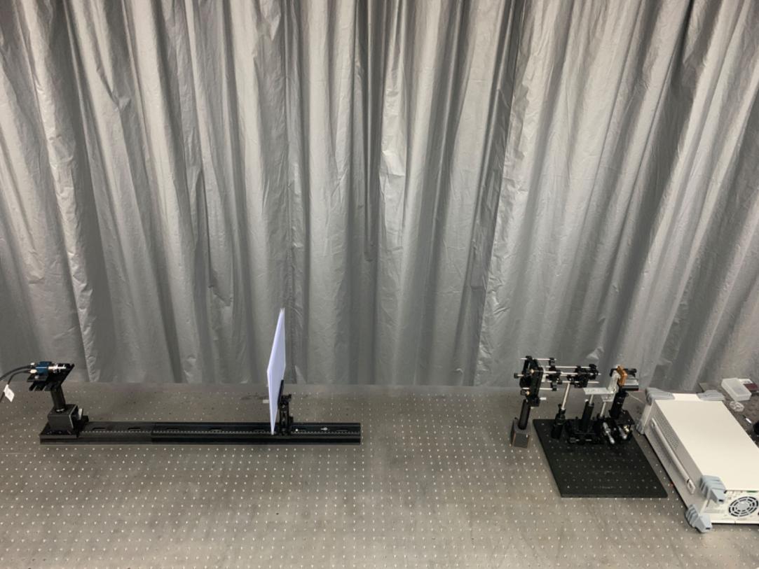
Figure 12. Underwater Antenna Testing Setup
Since the fixed power of the semiconductor laser is 5 W, direct imaging with a CMOS camera can lead to overexposure. To mitigate this, attenuation plates are added, and ground glass is introduced into the water tank until the CMOS detector no longer exhibits saturation. Original images are obtained from different underwater positions, and the divergence angles in the fast and slow axes are measured. Gaussian filtering is applied to the images to remove noise, and the images are centered and converted to grayscale.
By analyzing the grayscale values of the elliptical LD beam spot images, the energy distribution of the laser beam can be determined. The beam diameters in the fast and slow axes are obtained from the widths at the locations of maximum energy. The divergence angle of the laser beam is calculated using the formula:
\( θ=arctan{\frac{{D_{2}}-{D_{1}}}{L}}\ \ \ (9) \)
Where \( {D_{2}} \) and \( {D_{1}} \) are the beam diameters at different distances, and L is the distance between them. By capturing multiple sets of images of the spot, measuring their diameters, and calculating the average values, the fast and slow axis divergence angles are determined to be 0.315 mrad and 0.180 mrad, respectively, using Equation (4).
4.2. Energy Link Calculation of Optical Antenna
In optical communication systems, all gains and losses must be considered. Due to the complex diversity of underwater optical communication channels, only unobstructed point-to-point underwater connections are considered. The total link loss between the transmitter and receiver consists of underwater channel loss, geometric loss, and system intrinsic losses.
According to the literature, channel loss refers to the total loss caused by absorption and scattering in seawater. [6] It can be expressed as:
\( {Γ_{c}}={exp^{-cZ}}\ \ \ (10) \)
Where c is the loss coefficient. In clear seawater, the loss coefficient c(λ)=0.151. Calculating for a 100-meter transmission, the seawater channel loss is 65.58 dBm.
Due to the limitation of the receiving aperture size, not all of the emitted laser beam can enter the detector, resulting in a loss of optical energy, known as the geometric loss of the optical antenna.
The formula for calculating the geometric loss of the optical antenna is: \( {Γ_{geo}}=10{lg{(\frac{D}{2×Z×tan{(}\frac{θ}{2})+D})}^{2}} \) . Given that the diameter of the beam spot is 54mm and the measured maximum divergence angle is 0.315 mrad, the geometric loss for a 100-meter underwater transmission is calculated to be 3.98 dBm.
The power of the semiconductor laser is 5 W, equivalent to 37 dBm. The losses of components such as the beam splitter amount to 6 dBm. Therefore, the total loss is -75.56 dBm. Consequently, the total power reaching the detector at a distance of 100 meters underwater is -38.56 dBm, which exceeds the avalanche photodiode (APD) receiver threshold of -46 dBm, meeting the detection requirements. By reverse calculation, taking the receiver threshold of the APD detector as known, the maximum transmission distance is determined to be 110 meters.
Table 6. Overall Loss
Transmitting | Antenna and geometry | Channel | Beam splitter | Final |
37 dBm | -3.98dBm | -65.58dBm | -6dBm | -38.56dBm |
5. Conclusion
Addressing the significant divergence angle asymmetry and inherent image scatter issues of semiconductor laser beams, a method combining fast-slow axis collimator and beam expander is proposed. An underwater optical antenna is designed to effectively shape and collimate laser beams, reducing the difficulties in processing and adjustment. Experimental results demonstrate that the antenna system can meet the requirements for underwater propagation up to a distance of 100 meters. With small divergence angles and similar divergence angles for the fast and slow axes, the system boasts a simple structure, facilitating processing and adjustment. This makes it conducive to achieving rough tracking and precise alignment of underwater lasers.
Funding
Key Special Project of Suzhou Carbon Peak and Carbon Neutrality Technology Support (ST202219), Key Core Technology Research Project of Jiangsu Industrial Foresight (BE2022021; BE2022057), Nano-Vacuum Interconnect Test Station (2018-000052-73-01-000356), Jiangsu “Six Talent Peaks” High-level Talent Project (XYDXX-211).
References
[1]. Gong, H., Liu, Z., Li, G., et al. (2014). Fidelity study of diffractive laser beam expander. Chinese Journal of Lasers, 41(9), 38-43.
[2]. Liao, M., Wang, X., Jian, W., et al. (2016). Beam collimation of laser diode based on double-focus micro-lens. Laser & Infrared, 46(03), 294-299.
[3]. Yu, T., Wang, C., Zhang, Y., et al. (2015). Design and simulation of two-dimensional beam shaping system. Laser & Infrared, 45(11), 1360-1363.
[4]. Peng, H. (2011). Study on High Power Diode Laser with Beam Shaping and Beam Combining. Changchun Institute of Optics, Fine Mechanics and Physics, Chinese Academy of Science.
[5]. Wang, P., Xiang, Y., Gao, J., et al. (2015). Design of Collimating and Beam Expanding Laser System. Acta Optica Sinica, 35(09), 282-287.
[6]. Wang, T. (2019). Research on Modulation Technology of PL450B Laser for Underwater Laser Communication. Changchun University of Science and Technology.
[7]. Du, B., Gao, W., Li, J., et al. (2013). Design of aspherical lens for laser diode collimation based on ZEMAX. Laser & Infrared, 43(12), 1384-1388.
[8]. Lv, C., Zhan, R., Cui, Y., et al. (2021). Collimating lens design and aspheric optimization method of laser cauterization gun. Infrared and Laser Engineering, 50(03), 211-218.
[9]. Zhang, F., Wang, C., Geng, R., et al. (2007). Novel Collimator for Simultaneous Collimation of Fast and Slow Axis of Laser Diodes Array. Chinese Journal of Lasers, 2007(08), 1059-1063.
[10]. Gu, S., Guo, Y., Ju, Y., et al. (2022). Design of Optical Quality Detection System for Four-quadrant Detector Lens. Acta Optica Sinica, 42(02), 202-209.
[11]. Modinger, J. (2019). Lasers, death rays, and the long, strange quest for the ultimate weapon. Military Review, 99(4), 133.
[12]. Affan, S., Mohsin, M., Zubair, A. (2020). Survey and technological analysis of laser and its defense applications. Defence Technology, 2020(2), 012.
[13]. Zohuri, B. (2019). Laser Beam Energy as Weapon. In B. Zohuri (Ed.), Directed-Energy Beam Weapons (pp. 239-268). Cham: Springer.
[14]. Hu, H. (2006). Research on laser light weapons and their application in modern anti-terrorism operations. National University of Defense Science and Technology.
[15]. Hecht, J. (2009). Half a century of laser weapons. Optics and Photonics News, 20(2), 14-21.
[16]. Chen, X., & Wang, H. (2010). Anti-Terrorist Technical Equipment. Beijing: Science Press.
[17]. Jabczyński, J., & Gontar, P. (2020). Impact of atmospheric turbulence on coherent beam combining for laser weapon systems. Defence Technology, 2020(6), 021.
Cite this article
Zhang,K.;Ru,Z.;Ding,P.;Hao,K.;Han,T.;Wang,C.;Xiang,Y. (2024). Variable magnification beam expander system based on semiconductor laser. Theoretical and Natural Science,34,105-117.
Data availability
The datasets used and/or analyzed during the current study will be available from the authors upon reasonable request.
Disclaimer/Publisher's Note
The statements, opinions and data contained in all publications are solely those of the individual author(s) and contributor(s) and not of EWA Publishing and/or the editor(s). EWA Publishing and/or the editor(s) disclaim responsibility for any injury to people or property resulting from any ideas, methods, instructions or products referred to in the content.
About volume
Volume title: Proceedings of the 3rd International Conference on Computing Innovation and Applied Physics
© 2024 by the author(s). Licensee EWA Publishing, Oxford, UK. This article is an open access article distributed under the terms and
conditions of the Creative Commons Attribution (CC BY) license. Authors who
publish this series agree to the following terms:
1. Authors retain copyright and grant the series right of first publication with the work simultaneously licensed under a Creative Commons
Attribution License that allows others to share the work with an acknowledgment of the work's authorship and initial publication in this
series.
2. Authors are able to enter into separate, additional contractual arrangements for the non-exclusive distribution of the series's published
version of the work (e.g., post it to an institutional repository or publish it in a book), with an acknowledgment of its initial
publication in this series.
3. Authors are permitted and encouraged to post their work online (e.g., in institutional repositories or on their website) prior to and
during the submission process, as it can lead to productive exchanges, as well as earlier and greater citation of published work (See
Open access policy for details).
References
[1]. Gong, H., Liu, Z., Li, G., et al. (2014). Fidelity study of diffractive laser beam expander. Chinese Journal of Lasers, 41(9), 38-43.
[2]. Liao, M., Wang, X., Jian, W., et al. (2016). Beam collimation of laser diode based on double-focus micro-lens. Laser & Infrared, 46(03), 294-299.
[3]. Yu, T., Wang, C., Zhang, Y., et al. (2015). Design and simulation of two-dimensional beam shaping system. Laser & Infrared, 45(11), 1360-1363.
[4]. Peng, H. (2011). Study on High Power Diode Laser with Beam Shaping and Beam Combining. Changchun Institute of Optics, Fine Mechanics and Physics, Chinese Academy of Science.
[5]. Wang, P., Xiang, Y., Gao, J., et al. (2015). Design of Collimating and Beam Expanding Laser System. Acta Optica Sinica, 35(09), 282-287.
[6]. Wang, T. (2019). Research on Modulation Technology of PL450B Laser for Underwater Laser Communication. Changchun University of Science and Technology.
[7]. Du, B., Gao, W., Li, J., et al. (2013). Design of aspherical lens for laser diode collimation based on ZEMAX. Laser & Infrared, 43(12), 1384-1388.
[8]. Lv, C., Zhan, R., Cui, Y., et al. (2021). Collimating lens design and aspheric optimization method of laser cauterization gun. Infrared and Laser Engineering, 50(03), 211-218.
[9]. Zhang, F., Wang, C., Geng, R., et al. (2007). Novel Collimator for Simultaneous Collimation of Fast and Slow Axis of Laser Diodes Array. Chinese Journal of Lasers, 2007(08), 1059-1063.
[10]. Gu, S., Guo, Y., Ju, Y., et al. (2022). Design of Optical Quality Detection System for Four-quadrant Detector Lens. Acta Optica Sinica, 42(02), 202-209.
[11]. Modinger, J. (2019). Lasers, death rays, and the long, strange quest for the ultimate weapon. Military Review, 99(4), 133.
[12]. Affan, S., Mohsin, M., Zubair, A. (2020). Survey and technological analysis of laser and its defense applications. Defence Technology, 2020(2), 012.
[13]. Zohuri, B. (2019). Laser Beam Energy as Weapon. In B. Zohuri (Ed.), Directed-Energy Beam Weapons (pp. 239-268). Cham: Springer.
[14]. Hu, H. (2006). Research on laser light weapons and their application in modern anti-terrorism operations. National University of Defense Science and Technology.
[15]. Hecht, J. (2009). Half a century of laser weapons. Optics and Photonics News, 20(2), 14-21.
[16]. Chen, X., & Wang, H. (2010). Anti-Terrorist Technical Equipment. Beijing: Science Press.
[17]. Jabczyński, J., & Gontar, P. (2020). Impact of atmospheric turbulence on coherent beam combining for laser weapon systems. Defence Technology, 2020(6), 021.