


The Workings of a Jet Engine
Lance Zonglin Du
11 Bryant Ave. Glendowie, Auckland, New Zealand
lance1220du@icloud.com
Abstract. This document explains and explores the basics of the jet engine, from basic physical knowledge to the inner workings of the engine, as well as the maintenance aspect. It touches on the mechanical properties that allow the jet engine to function, the design considerations, the mechanisms within the engine, and finally the maintenance of the engine.
1. Introduction
The jet turbine is a modern invention with many uses, such as propelling aeroplanes, powering ships, and generating electricity. However, a jet engine can cost from 10 to 40 million dollars [1], and with these high costs comes a high amount of maintenance. To fully appreciate the beauty of the jet engine, this report will explore the two main aspects: mechanics and modus operandi. More specifically, this report will begin with covering the history of the jet engine, then explore the different forces acting on an aircraft and the other propulsive systems. After learning the aerodynamic forces involved, this work will examine the design process of the jet engine and its internal workings. Finally, the report will explore the maintenance involved with a jet engine. Overall, this report will act as an introduction for further study into the operation of the jet engine.
2. Mechanical properties
This section discusses the key mechanical properties required for a deeper understanding of the jet engine.
2.1. Stress
When an external force is applied to a body, the internal resistance exhibited by that body or material is the direct stress experienced by the object[2], denoted by sigma, σ. Direct forces are the force that causes stress in the body, and there are two types of direct forces: compression and tensile. Compression force would shorten a body and have a negative value, while a tensile force would elongate a body and have a positive value. Stress is calculated using the equation
\( σ=F/A \)
Where F is the applied force and A is the cross-sectional area, measured in Pascals ( \( \frac{N}{{m^{2}}} \) )[2].
2.2. Strain
Strain is the amount of deformation caused by an external force in a body[2]. Strain has the symbol epsilon, ε, and can be calculated with the formula
\( ϵ=\frac{x}{L} \)
Strain is the ratio of the deformation to the original length; therefore, it does not have a unit[2].
2.3. Stress-Strain diagram
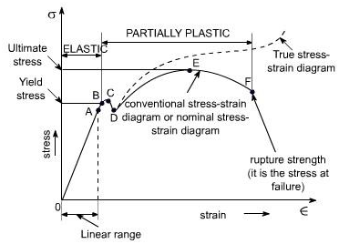 The body’s reaction to stress and strain can be plotted on a graph called the stress-strain curve (Figure. 1)[3], which shows how the material will perform under load. The modulus of elasticity, E, determines the stiffness of a material in the elastic section of the graph and can be calculated with the gradient of the line[4].
The yield stress is where the plastic section of the graph begins, and if the force exceeds this amount, the body will deform plastically, not returning to its original shape. The proportional limit is where the graph turns from a straight line to a curve but still responds elastically.
After the linear region, there is the plastic region. Strain hardening happens after yielding, becoming stiffer as more stress is experienced. This increase in stiffness stops when reaching ultimate stress, where the material is experiencing the maximum amount of strain, shown by the flat gradient.
After the ultimate stress, necking occurs, where the cross-sectional area begins to decrease, caused by slip planes within the material, shown by the downward curve. Necking would eventually lead to fracture, where the graph ends.
The maximum principal stress is the sum of the normal and shear stress and is used to calculate the total stress of a body.
2.4. Shear stress
Shear stress is the component of stress along a plane that causes deformation due to slippage and is denoted by Tau[2]. Shear stress is calculated with
\( τ=F/A \)
A positive shear would indicate that the force is pushing downwards with respect to the fixed end, while a negative shear would indicate the force is pushing upwards. Shear forces can be seen in examples such as a transverse load on a beam, which can be seen on a diving board, or when a pair of shears cut material, as the shears are trying to split the material apart. To increase the shear strength, a part can either be designed to have a larger surface area or larger grains in the body.
2.5. Shear strain
Shear strain, denoted by lowercase gamma, γ, is the strain caused by a shear force.[2] Shear strain is calculated with
\( γ=x/L \)
Shear strain is also a ratio calculated with the change in distance to the object’s height. The rigidity of elastic material can be defined with the Modulus of Rigidity(G) and is calculated with
\( G=τ/γ \)
The higher the number, the less a body deforms with a shear force.
2.6. Fatigue
Fatigue is the failure that occurs in structures that are objected to cyclic stress and at stress under the ultimate stress. The number of cycles a material can undergo safely at specific stress can be shown through an S-N Curve. There is a finite life section for material and an infinite life section, where the stress is low and can be cycled at this stress indefinitely. Fatigue happens with a crack, usually at a point of high-stress concentration, such as dents, threads and scratches. The crack then advances incrementally with every stress cycle. When it reaches a critical size, final failure occurs[3].
2.7. Creep
Creep is the plastic deformation of material over time under constant load and usually occurs at high temperatures[5]. Therefore, it is an important consideration when designing high-temperature parts such as the jet engine turbine. However, while creep happens at any temperature, it is only measurable at 40 per cent of the material’s melting point.
Creep happens in several stages. The initial extension portion has a steep gradient and is partly within the elastic region. The next portion is where the rate of deformation decreases over time, also called the transient or primary creep. The next segment is a very predictable and linear portion, and the amount of time the material spends in this region depends on the stress the material undergoes. Finally, the last portion of the graph shows a rapid increase in creep rate whereafter, the material fails[6].
2.8. Creep mechanics
Creep is influenced by the stress and the temperature the material experiences, where a higher amount of either increases the creep rate[5]. These variables affect the creep mechanism, including dislocation related, diffusional, and grain boundary sliding. Due to the grain boundaries being weaker than the grain interior, the grains are able to slide past each other. Grains are the structure unit within the material and are made up of randomly placed crystal structures. Therefore the more prominent the grain size, the less creep would occur due to the low amount of grain boundaries; however, the material would be more brittle due to the lack of grains.
2.8.1. Minimising creep. Creep must be avoided when designing components to ensure the system’s safety. Materials with the following properties generally have a reduced creep rate: large grain size, high melting point, and high elastic modulus. This is why nickel-based superalloys are used to produce turbine blades within a jet engine[7].
3. Engine design
3.1. Initial research
Jet engines were developed during WWII, where much funding was given to new technologies that could potentially win the war for their respective countries. The jet engine came about as a replacement for the internal combustion engines due to their limitations at higher speeds. The jet engine is therefore designed to perform at higher efficiencies at higher speeds. The first turbojet was developed by Dr Hans Von Ohain, and the first turbojet prototype outside of Germany was developed and run by Sir Frank Whittle in 1937[8].
3.2. The brayton cycle
The Brayton cycle (Figure. 2)[9] illustrates the thermodynamic cycle of a working fluid within an engine. The intake air’s velocity decreases upon entry while its pressure increases. This is explained using Bernoulli’s principle, as the kinetic energy of the moving air is being converted into pressure[10]. The compressor further compresses the air to ensure maximum efficiency. Combustion then occurs between 3 and 4, where the volume of the gas increase due to the additional gas introduced from the combustion process. The hot gases then do work on the turbine, where both temperature and pressure decrease. The exhaust is then finally exhausted into the atmosphere in order to create thrust. The diagram is useful as the area under the curve can be used to calculate the thrust 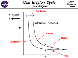 created[9].
Heat changes often occur within a jet engine, as the air experiences compression, combustion and expansion. Due to the ideal gas laws, pressure, volume and temperature are proportional to each other, and changes in any one of these factors affect all. When the air is compressed, the volume decreases, and therefore the temperature and pressure increase. When combustion occurs, additional hot gases are introduced, which further increases temperature and pressure. When expansion occurs, the volume increases, which causes both the pressure and temperature to drop[11]. The change in heat is therefore proportional to the change in work.
3.3. Bypass ratio
The bypass ratio is the ratio between the amount of air that is directed into the combustion engine and the amount of air that is only used to generate thrust[12]. A low bypass ratio means less air is being directed around the combustion chamber, which increases the operating speed at the expense of fuel efficiency. This is often used in military applications where high power-to-weight ratios are critical. A high bypass ratio engine has higher efficiency, although having a lower speed limit, and is often used in passenger jets.
3.4. Environmental impact
In recent times, the focus on environmental effects has been gathering more attention, and jet aircraft, although efficient, still harms the environment[13]. Jets have two main environmental pollutants: Noise and emissions. Aircraft noise is caused by the turbulent airflow around the aircraft, such as the jet exhaust and landing gears. Emissions of the aircraft include the carbon dioxide and nitrogen oxides that are produced due to the combustion process, water vapour which contributes to the greenhouse effect, and contrails where it can remain and even grow under the right conditions.
4. Jet engine’s working
4.1. Types of jet engines
A jet engine is a term that contains multiple propulsion systems, including turbojets, turbofans, and turboprops[14]. Turbojets are engines whose exhaust only consists of gases that have been through the combustion chamber, with no bypassed air. This type of jet engine is the least efficient, although it can achieve the highest speed out of all three designs, excluding ramjets and other types. This type is mostly used in military jet fighters. Turbofan engines are engines whose exhaust consists of both combusted gases and bypass air. Turbofan engine’s efficiency is related to its bypass ratio, a ratio of combusted air and air that has not been through the combustion chamber and has only been accelerated by the primary fan blade. This type of jet engine is more efficient than the turbojet, although it cannot operate at as high of a velocity and is used in mostly civilian airliners. The last type out of the three is the turboprop design. Compared to the other two types, the turboprop uses high-velocity air to drive a turbine instead of exhausting it, which drives a shaft and uses a propeller to propel the craft. This type of engine is the most efficient, although it can only operate at low speeds, and it is most commonly used in regional airliners and personal aircraft. Its variant, the turboshaft, is used in various tasks, from being used in helicopters to tanks.
4.2. Parts of a jet engine
The jet engine consists of multiple parts, usually consisting of an air intake, a compressor, a combustion chamber, a turbine and a nozzle[14].
An air intake’s role is to direct air into the engine while ensuring all supersonic flow is being slowed down to subsonic. It also has to be designed to not pick up any debris from the ground to avoid damage, put in a place where water spray from the landing gear is not ingested, and the flow directed into the engine is laminar.
A compressor consists of many rotor blades and stator blades, and its role is to compress the air to ensure high combustion efficiency, as a higher pressure means there is more oxygen for combustion to occur. A compressor consists of many stages, out of which the primary fan blade is the most prominent part, as it is at the front of the engine and is the only fan blade that accelerates the bypass air. The other compressor stages compress the air down, reaching the required pressure when it reaches the combustion chamber.
The combustion chamber’s role is to inject and combust the fuel with the oxygen in the air and expand the gas, which leaves the engine at high speed. The turbine is similar to the compressor, but instead of adding energy to the air, it subtracts energy and turns the high temperature and high-pressure gas into useful work that is transmitted through a shaft to the compressor to continue the combustion process. In addition, the nozzle plays an important role in accelerating the exhaust gas to make the engine more efficient. A nozzle can also have other components added on, such as a thrust reverser to redirect the flow of the gas to slow the plane down when landing or an afterburner to increase thrust significantly for a short period of time.
5. Cooling
Cooling is an essential part of the jet engine working, as the efficiency of the engine increases with the maximum temperature that can be achieved by the engine. Therefore, it is essential to maximise the combustion temperature in the jet engine. There are multiple ways of cooling turbine blades, including internal cooling, micro fins within internal cooling, film cooling, and transpiration cooling[15].
5.1. Internal air system
The internal air system is a system of air delivery components that, although not contributing to the thrust, is necessary to achieve high efficiency, among other tasks. Its functions include: Internal engine and accessory unit cooling; Seals for hot gas ingestion protection; Bearing axial load control; Turbine tip clearance control; and, Anti-ice within the engine[15].
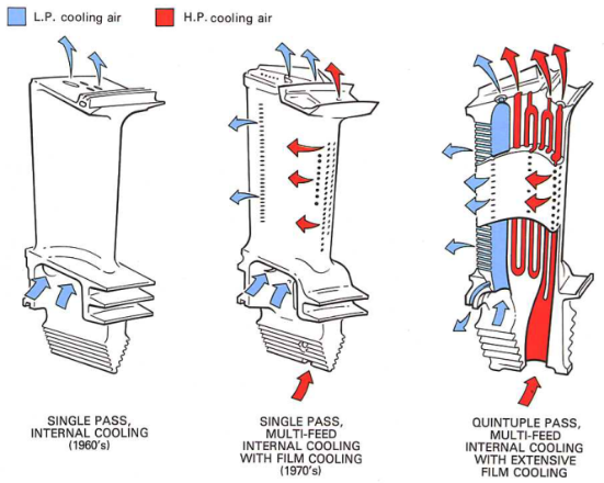
This system is around 1/5 of the total mass of the engine. The cooling system either cools or heats up each part to increase the temperature evenly. This is important in cases such as the turbine blades to ensure an adequate seal and maximise efficiency. This is also important in different seals, as uneven thermal expansion may cause leaks. There are several ways to cool a turbine blade (Figure. 3)[15], which include single-pass internal cooling, often used in the 1960s, where the air is passed through holes within the turbine; single pass, multi-fed internal cooling with external film cooling, often used in the 1970s, where different gas sources are used for internal and external film cooling; and quintuple pass, multi-fed internal cooling with external film cooling, where the passage of the internal cooling paths are bent to increase surface area, and a larger amount of holes are used for film cooling.
6. Fluid systems
There are three fluids that make up the fluid system in a gas turbine: air, fuel and oil. These fluid systems heat, cool, seal and lubricate the components in the jet engine[15].
6.1. Air system
The primary air function of the air system is the engine air, where it is either bypassed and produces thrust or is compressed to increase the amount of oxygen and is combusted with fuel to produce power[15]. The secondary functions are uses that are not directly used for power generation. This includes cooling, sealing and control of bearing loads. Gas turbine efficiency is calculated with turbine entry temperature(TET), and the higher this temperature, the more efficient the turbine. Therefore, to reach high efficiency, the turbine must reach temperatures around 1600°C, which would melt the turbine if not cooled. The air that cools the turbine comes from the compressor. Although the cooling air is around 700°C, it is much lower than the turbine temperatures, and therefore the cooling air cools the turbine enough to reduce creep and melting of the blades. This reduction in temperature also increases the engine’s lifespan as using the part at a reduced temperature means it is being loaded to a lower per cent of the yield strength, which reduces the fatigue experienced, thus increasing the safe limit of operation. Another way of providing cooling air is through atmospheric air, as it is much cooler and more readily available, although with the downside of additional drag. Air also need to be supplied to the turbine casing as an even and controlled thermal expansion is important due to the tight tolerances in a jet engine. The even thermal expansion also reduces the stress experienced by the part, thus also extending the life of the component.
Seals are also another part of the overall air system in a gas turbine. The seals reduce air leakage and direct air to where it is needed instead of being wasted, which is an opportunity cost. Different seals in an engine may include labyrinth seals, where the air has to traverse through complicated routes, which reduces their pressure and prevents a loss in pressure; Brush and leaf seals have a rotating part and bristles, which maintains contact with the rotating part which creates a tight seal. Carbon seals are seals that use the positive pressure of one side to utilise the low friction properties of carbon to produce a seal. This type of seal often requires oil cooling due to the large amount of heat produced. Static seals are seals that are used when two parts are not moving relative to each other and therefore is, simpler than the other types[15].
Another use of the air system is the control of bearing loads. This is used to counter the force produced due to the forward force of the compressor and the backward force of the turbine. This bearing control spreads the load over a larger area; therefore, the point load is reduced. This is also used to prevent the overloading or underloading of bearings, as either can produce problems that require repairs[15].
The design challenge of the air system is due to the changing pressure, speeds, and temperatures at which the turbine will be operated, and all failure possibilities must be considered, examined and tested to ensure the safe operation of the engine under normal circumstances.
6.2. Fuel systems
The FADAC(Full Authority Digital Engine Control) system is a system that controls the engine(s)[15]. This system is made up of several parts, including EEC(Electronic engine controller), which is the computerised system for the FADAC; FOHE(Fuel Oil Heat Exchanger), which both heats the fuel and cools the oil, as well as pressurising, filtering and delivering fuel to the engine; and FMU(Fuel Metering Unit) which regulates the fuel consumption. This reduces the number of personnel required to operate the engines, as older planes such as the concord had a third seat onboard for the flight engineer, whose main job is to monitor and operate the engine systems. This, along with other positions such as navigator and radio operator, has been proved redundant due to improved technology.
Fuel storage is also an important part of the engine system. Modern airliners usually have two wing tanks and a centre tank. The centre tanks are usually drained as the weight of the fuel on the wings reduces the dihedral of the wings, which increases the wing’s efficiency. Fuel tank venting is also an important part as there is a big difference in pressure between the tank and the atmosphere, which would potentially cause a rupture and, therefore, a risk of fire and loss of fuel. Fuel shut-off valves are also crucial, as in the case of an engine fire, the fuel must be isolated to prevent an explosion.
6.3. Oil system
The oil system is another fluid system in a gas turbine[15]. It has the purposes of lubrication, cooling, sealing and preventing corrosion of parts, which extends the life and maintains the efficiency of an engine. Oil and lubricants are regularly replaced during maintenance to maintain the freshness of the liquids, as well as refill any that the engine systems have used up and replace any broken down components in the oil. However, in contrast to the oil itself, the oil system components are not usually replaced over the engine’s life and therefore need to be designed to sustain the load.
7. Maintenance
7.1. Types of maintenance
Maintenance is an important part of jet engine operations, and its main goal is to increase engine reliability and reduce the cost of operation to be able to be used safely on aeroplanes. There are two types of maintenance from the maintainer’s point of view: overhaul and line maintenance. Overhaul maintenance is where the engine is removed from the aircraft and is used for all letter checks, where the frequency of the maintenance is defined by a letter from A to D. A checks are usually the most frequent, usually performed every 120-150 flight hours, and D checks are usually the most extensive, performed every 6-10 years.[16] This is not preferred over line maintenance due to the increased time needed. Line maintenance is when the maintenance of the engine is done on the aircraft itself, without taking off the engine. In terms of sequencing, there are also two types of maintenance: scheduled and unscheduled. Scheduled maintenance is done on a cyclical basis and is planned out of precaution. The period of time is determined by tests conducted during the certification process, which find the minimum amount of time between faults and from there, the maintenance frequency is found. This can be categorised into cleaning, inspection, functional checks, lubrication, restoration and discard. Unscheduled maintenance is the unexpected faults or failures that need to be fixed. This is the type of event that scheduled maintenance is trying to prevent, as these events could cause delays due to the time required to repair. The maintenance aspect must also be considered when designing engines, such as making the modules more easily removable, so replacement is faster.
7.2. Gas turbine health monitoring
Monitoring of gas turbines is an important part of gas turbine operation, as it may reduce the cost of repairing(downtime), increase reliability, reduce the environmental effects and increase the safety of personnel. There are different ways of turbine monitoring. It used to be done by taking apart the turbine or inspecting through inspection windows physically on-site with an engineer; however, using today’s technology, we can monitor the turbine from far away over the internet using sensors and cameras. This reduces the cost and complexity for the operator, as engineers do not have to travel to the turbine, but can do all monitoring from a central station, increasing efficiency[15].
There are a few methods for condition monitoring. There is performance-based, e.g. Gas path analysis, non-performance based (Oil sample, vibration, etc.), onboard monitoring and finally, off-board monitoring. The data gathered is then compared to the engine performance model. Then if the data between the two turbines are different, then the fault can be identified. This operation aims to reduce or eliminate shutdowns, reduce costs, and increase performance[15].
7.3. Maintenance strategies
There are three main maintenance strategies: corrective, preventive and predictive. Corrective maintenance is where repairs are done after a failure, also known as a reactive-based strategy. This type is the least efficient due to its unscheduled nature, which can cause major disruptions to usage. Preventive maintenance is where inspections and maintenance are done at regular intervals, known as a time-based strategy, similar to the letter checks for aircraft. The optimal interval that suits the criteria of interest(cost, reliability, etc.) is calculated using average failure rate data. The last type of maintenance is predictive maintenance, a condition-based strategy where the degradation of the equipment is constantly monitored with health assessment, prognostics and diagnostics. If any sign shows a potential failure, a repair is carried out just in time. This type of maintenance is the most data-intensive and requires up-to-date technology. Borescope inspection techniques are also used in modern-day inspections, as it does not require the opening of the engine and therefore save time.[15]
8. Summary
In conclusion, the jet engine is a complicated yet elegant piece of engineering that has been designed to attain maximum efficiency while having high performance. This report encapsulates countless hours of eye-opening study of a marvellous machine. The exploration began with the basic physics knowledge that is fundamental to the design process, then how it is designed. After that, this report describes the inner workings of the engine, as well as its various systems, and finally finishes off with the maintenance aspect of the engine.
References
[1]. 5 Facts About Jet Engines | Blog- Monroe Aerospace. (2020, December 30). Monroe Aerospace. Retrieved February 5, 2022, from https://monroeaerospace.com/blog/5-facts-about-jet-engines/.
[2]. SIMPLE STRESS AND STRAIN. (n.d.). Weebly. Retrieved April 25, 2022, from https://intuitionke.weebly.com/uploads/1/1/8/2/118271274/book_on_mechanics_of_materials_simple_stress_and_strain_.pdf.
[3]. Material Fatigue Definition. (2016, March 15). COMSOL. Retrieved March 25, 2022, from https://www.comsol.com/multiphysics/material-fatigue.
[4]. Velling, A. (2021, December 30). Stress-Strain Curve. Fractory. Retrieved April 25, 2022, from https://fractory.com/stress-strain-curve/.
[5]. Altenbach, H., & Eisenträger, J. (2019, January). Introduction to Creep Mechanics. ResearchGate. Retrieved April 25, 2022, from https://www.researchgate.net/publication/336510171_Introduction_to_Creep_Mechanics.
[6]. Corrosionpedia. (2018, June 22). Creep. Retrieved March 25, 2022, from https://www.corrosionpedia.com/definition/344/creep-material-science.
[7]. Kassner, J. S. T. (2008). Superalloys - an overview | ScienceDirect Topics. Science Direct. Retrieved March 25, 2022, from https://www.sciencedirect.com/topics/chemistry/superalloys.
[8]. History of flight - The jet age. (n.d.). Encyclopedia Britannica. Retrieved April 25, 2022, from https://www.britannica.com/technology/history-of-flight/The-jet-age.
[9]. Glenn Research Center. (n.d.). Ideal Brayton Cycle [Graph]. https://grc.nasa.gov/www/k-12/airplane/brayton.html.
[10]. What is Bernoulli’s equation? (article). (n.d.). Khan Academy. Retrieved April 25, 2022, from https://www.khanacademy.org/science/physics/fluids/fluid-dynamics/a/what-is-bernoullis-equation.
[11]. Nave, R. (n.d.). Ideal Gas Law. Hyperphysics. Retrieved April 25, 2022, from http://hyperphysics.phy-astr.gsu.edu/hbase/Kinetic/idegas.html.
[12]. bypass ratio. (n.d.). The Merriam-Webster.Com Dictionary. Retrieved March 25, 2022, from https://www.merriam-webster.com/dictionary/bypass%20ratio[8] Information on http://www.weld.labs.gov.cn.
[13]. Aviation’s impact on the environment. (n.d.). Aviation Benefits. Retrieved April 25, 2022, from https://aviationbenefits.org/environmental-efficiency/aviations-impact-on-the-environment/.
[14]. Engines. (n.d.). NASA. Retrieved April 25, 2022, from https://www.grc.nasa.gov/www/k-12/UEET/StudentSite/engines.html.
[15]. Rolls-Royce plc. (1986). The Jet Engine (5th ed.). Rolls-Royce plc.
[16]. K, E. (2019, January 13). A B C D check – Airline Maintenance – ABCD.XXX. StudyFlying. Retrieved April 25, 2022, from https://studyflying.com/a-b-c-d-check-airline-maintenance/.
Cite this article
Du,L.Z. (2023). The Workings of a Jet Engine. Theoretical and Natural Science,2,126-134.
Data availability
The datasets used and/or analyzed during the current study will be available from the authors upon reasonable request.
Disclaimer/Publisher's Note
The statements, opinions and data contained in all publications are solely those of the individual author(s) and contributor(s) and not of EWA Publishing and/or the editor(s). EWA Publishing and/or the editor(s) disclaim responsibility for any injury to people or property resulting from any ideas, methods, instructions or products referred to in the content.
About volume
Volume title: Proceedings of the International Conference on Computing Innovation and Applied Physics (CONF-CIAP 2022)
© 2024 by the author(s). Licensee EWA Publishing, Oxford, UK. This article is an open access article distributed under the terms and
conditions of the Creative Commons Attribution (CC BY) license. Authors who
publish this series agree to the following terms:
1. Authors retain copyright and grant the series right of first publication with the work simultaneously licensed under a Creative Commons
Attribution License that allows others to share the work with an acknowledgment of the work's authorship and initial publication in this
series.
2. Authors are able to enter into separate, additional contractual arrangements for the non-exclusive distribution of the series's published
version of the work (e.g., post it to an institutional repository or publish it in a book), with an acknowledgment of its initial
publication in this series.
3. Authors are permitted and encouraged to post their work online (e.g., in institutional repositories or on their website) prior to and
during the submission process, as it can lead to productive exchanges, as well as earlier and greater citation of published work (See
Open access policy for details).
References
[1]. 5 Facts About Jet Engines | Blog- Monroe Aerospace. (2020, December 30). Monroe Aerospace. Retrieved February 5, 2022, from https://monroeaerospace.com/blog/5-facts-about-jet-engines/.
[2]. SIMPLE STRESS AND STRAIN. (n.d.). Weebly. Retrieved April 25, 2022, from https://intuitionke.weebly.com/uploads/1/1/8/2/118271274/book_on_mechanics_of_materials_simple_stress_and_strain_.pdf.
[3]. Material Fatigue Definition. (2016, March 15). COMSOL. Retrieved March 25, 2022, from https://www.comsol.com/multiphysics/material-fatigue.
[4]. Velling, A. (2021, December 30). Stress-Strain Curve. Fractory. Retrieved April 25, 2022, from https://fractory.com/stress-strain-curve/.
[5]. Altenbach, H., & Eisenträger, J. (2019, January). Introduction to Creep Mechanics. ResearchGate. Retrieved April 25, 2022, from https://www.researchgate.net/publication/336510171_Introduction_to_Creep_Mechanics.
[6]. Corrosionpedia. (2018, June 22). Creep. Retrieved March 25, 2022, from https://www.corrosionpedia.com/definition/344/creep-material-science.
[7]. Kassner, J. S. T. (2008). Superalloys - an overview | ScienceDirect Topics. Science Direct. Retrieved March 25, 2022, from https://www.sciencedirect.com/topics/chemistry/superalloys.
[8]. History of flight - The jet age. (n.d.). Encyclopedia Britannica. Retrieved April 25, 2022, from https://www.britannica.com/technology/history-of-flight/The-jet-age.
[9]. Glenn Research Center. (n.d.). Ideal Brayton Cycle [Graph]. https://grc.nasa.gov/www/k-12/airplane/brayton.html.
[10]. What is Bernoulli’s equation? (article). (n.d.). Khan Academy. Retrieved April 25, 2022, from https://www.khanacademy.org/science/physics/fluids/fluid-dynamics/a/what-is-bernoullis-equation.
[11]. Nave, R. (n.d.). Ideal Gas Law. Hyperphysics. Retrieved April 25, 2022, from http://hyperphysics.phy-astr.gsu.edu/hbase/Kinetic/idegas.html.
[12]. bypass ratio. (n.d.). The Merriam-Webster.Com Dictionary. Retrieved March 25, 2022, from https://www.merriam-webster.com/dictionary/bypass%20ratio[8] Information on http://www.weld.labs.gov.cn.
[13]. Aviation’s impact on the environment. (n.d.). Aviation Benefits. Retrieved April 25, 2022, from https://aviationbenefits.org/environmental-efficiency/aviations-impact-on-the-environment/.
[14]. Engines. (n.d.). NASA. Retrieved April 25, 2022, from https://www.grc.nasa.gov/www/k-12/UEET/StudentSite/engines.html.
[15]. Rolls-Royce plc. (1986). The Jet Engine (5th ed.). Rolls-Royce plc.
[16]. K, E. (2019, January 13). A B C D check – Airline Maintenance – ABCD.XXX. StudyFlying. Retrieved April 25, 2022, from https://studyflying.com/a-b-c-d-check-airline-maintenance/.