


1.Introduction
Wearable medical devices have gained attention due to their potential for preventing and treating chronic diseases and reducing mortality, which is especially important in an aging society. Microelectronics, communication, and signal processing technology advancements have made physiological signal acquisition systems a research hotspot. These systems can acquire electrocardiogram, electroencephalography, electromyography, and other physiological signals in real-time for long-term monitoring of patients with cardiovascular diseases, epilepsy, etc. Analog front-end (AFE) is crucial in wearable medical devices as it collects and amplifies biological signals, and its performance determines the system’s signal quality.
The front end of a bio-signal acquisition system is shown in Figure 1. The system typically consists of an AFE, which usually utilizes an Instrumentation Amplifier (IA) to amplify and filter the biological signals obtained from the electrodes. The amplified signals are then converted from analog to digital signals by an Analog-to-Digital Converter (ADC) for ease of subsequent processing and transmission. The obtained digital signals are initially processed by a Digital Signal Processor (DSP) and then transmitted to the corresponding receiving device via a wireless communication module. In addition to the signal chain, on-chip power management modules are typically included in the system to provide appropriate and stable power supply to the device [1].
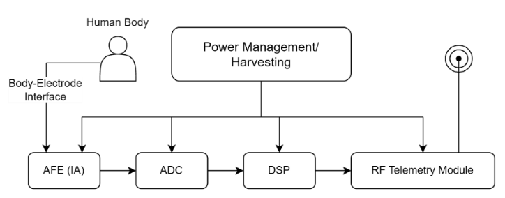
Figure 1. Portable biological signal acquisition system
Biological signals typically have low frequencies and amplitudes. Figure 2(a) shows the measurable electrical and blood activity related signals around the human body. Figure 2(b) illustrates the frequency and amplitude distributions of different kinds of electrical signals in the human body [2]. However, there are often many low-frequency and high-amplitude interferences in the acquisition system and environment, such as power line coupling to the human body’s common mode interference, electrode-generated offset voltage, and circuit noise. These challenges place high demands on the performance of the AFE design.
|
(a) |
(b) |
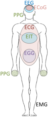
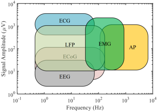
Figure 2. Biopotential signals. (a)Human biological signal [1]; (b)The distribution, frequency and amplitude of bioelectrical signals[3]
To extract high-quality signals under such conditions, the AFE of the biological signal acquisition system requires high input impedance, high common-mode rejection ratio (CMRR), bandpass filtering, low noise, and low offset [4]. In amplifier circuits, noise and power consumption are usually negatively correlated, meaning that amplifier noise can be reduced by increasing the amplifier current. Therefore, the AFE in the biological signal acquisition system needs to be carefully designed to meet the needs of wearable medical devices. The main content of this paper is the research and design of the IA in the AFE.
In a biological signal acquisition system, the function of the IA is to amplify the electrical signal coupled to the front electrode, while filtering out other noise and interference within the signal frequency range. As biological signals have low frequency and small amplitude, and the acquisition environment often contains large amounts of common mode interference and electrode offset, these factors present challenges in the design of the IA [5].
This article discusses the key characteristics of the capacitively-coupled chopper instrumentation amplifier (CCIA) in biological signal acquisition systems. These include high CMRR, low bandwidth, high-pass filtering, low noise, adjustable gain and bandwidth. These characteristics ensure effective mitigation of interference signals, preservation of signal quality, and adaptability to diverse applications. The analog front-end in this paper employs a CCIA, with the core OTA utilizing fully-differential folded cascode. To improve CMRR, common-mode feedback (CMFB) is introduced. To reduce 1/f noise, chopper modulation was employed to reduce its effects.
2.System Structure
2.1.Literature Review
IA for biological signal acquisition has been developed for several decades, resulting in various different topological structures. The most traditional structure is the three-op-amp IA, which was originally used in automation control systems and was later found to be suitable for detecting biological signals [6-8]. The advantages of the three-op-amp structure are high input impedance, but the disadvantages are high power consumption and limited CMRR. The switch-capacitor structure is an IA structure that uses switch capacitors [9-10]. Although switch capacitors can eliminate flicker noise in amplifiers, this structure can lead to noise folding effects and increase noise [11]. Toumazou proposed a current-mode IA in 1989, which converts signals to the current domain and achieves lower noise and power consumption, as well as a high CMRR of 80dB [12]. Harrison published a capacitively-coupled structure that uses capacitors as feedback elements and utilizes pseudo-resistance to achieve large bias resistors [13]. This structure has low power consumption, high gain accuracy, and is fully integrated on-chip. Many subsequent designs have referred to this structure. Denison proposed an IA that utilizes chopping modulation technology, achieving lower noise and higher CMRR of over 100dB at low frequencies [14]. In addition, there is a current feedback structure, which uses input and feedback transconductance amplifiers for feedback and has a high CM input impedance of 30MΩ and a high CMRR of 92dB [15-16].
2.2.Signal Collecting Electrode
Electrodes are vital in acquiring biological electrical signals by converting ion flow into electronic flow in the circuit, and they determine the noise and performance of the system. Wet, dry, and non-contact electrodes are commonly used. However, for long-term wearable medical devices, dry electrodes are preferred. This paper focuses on simulating dry electrodes that directly contact the skin with a metal surface, consisting of a megohm-level resistance and a nano-farad-level capacitor in parallel [1].
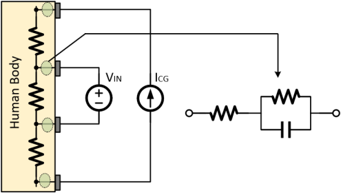
Figure 3. Skin-electrode interface coupling model for biological signal acquisition
Figure 3 shows the traditional bioimpedance measurement with four electrodes. The input of the reading front-end contains only information about the bioimpedance. If the measured input impedance is large enough, no current flows into the impedance of the sensing electrode, and the voltage input signal can be expressed as equations 1:
\( {V_{IN}}={Z_{BIOZ}}×{I_{CG}}\ \ \ (1) \)
The bioimpedance model also includes the case of a series combination of resistance and capacitance. The relationship between bioimpedance, coupled capacitance, resistance, and frequency in the human body is depicted in Figure 4. The mathematical expressions representing their relationship are as equations 2:
\( {Z_{BIOZ}}=R+\frac{1}{i∙2π∙f∙C}\ \ \ (2) \)
|
|
|
|
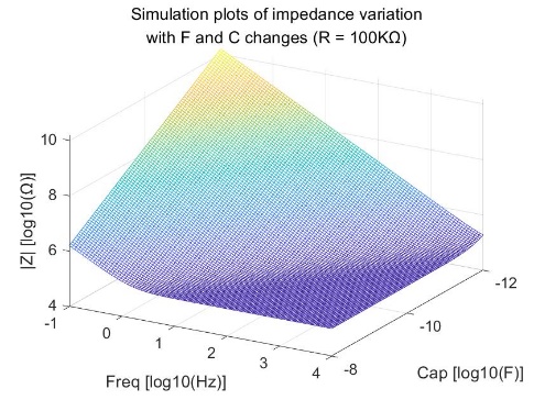
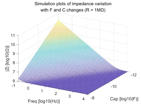
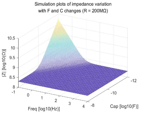
Figure 4. Simulation plots of impedance variation with F and C changes
In four-electrode measurements, common noise sources include BIOZ channel noise, IA noise, CG noise, and reference current noise. The relationship between these noises can be expressed by the following formula 3:
\( {\overline{{V_{N}}}^{2}}={\overline{{V_{N,BIOZ}}}^{2}}+{\overline{{V_{N,IA}}}^{2}}+{\overline{{V_{N,CG}}}^{2}}+{\overline{{V_{N,REF}}}^{2}}\ \ \ (3) \)
The effects of CG and reference current noise can be reduced by equipment design and proper electrode and amplifier selection, and the noise is normally negligible [17]. However, BIOZ channel and IA noise are unavoidable but can be minimized by choosing low-noise amplifiers, filters, adjusting electrode positions, and increasing signal amplitude.
2.3.Chopper Modulation
Three identical choppers are used in the IA design. The flowchart of chopper modulation is shown in Figure 5(a). The input signal\( {V_{in}} \)is modulated by\( {CH_{in}} \), and is converted to a voltage by\( {C_{in}} \)and\( {C_{f}} \). The demodulated signal at the original frequency is amplified and appears at the output. The offset voltage and flicker noise of the OTA are modulated to high frequencies by\( {CH_{out}} \), and are finally output through LPF.

Figure 5. Chopper modulation. (a) Principle of chopper modulation; (b) Input impedance of CCIA; (c) Structure of the chopper
Chopping modulation greatly improves the CMRR of the CCIA but introduces chopping capacitors that reduce the input impedance of the CCIA, which is shown in Figure 5(b). The function of the input impedance as formula 4:
\( {Z_{in}}=\frac{1}{2{f_{ch}}{C_{in}}}\ \ \ (4) \)
However, careful circuit design and bootstrapping can mitigate this effect. Despite the reduction in input impedance, the benefits of improved CMRR usually outweigh this drawback.
The chopping circuit used in this design is shown in Figure 5(c). The chopper consists of four CMOS switches, combining PMOS and NMOS devices, with complementary switches to reduce charge injection, so that opposite charges are injected into two channels [18]. In order to ensure that\( {Δq_{n}} \)cancels out\( Δ{q_{p}} \)exactly, we must ensure that (formula 5):
\( {W_{N}}{L_{N}}{C_{ox}}({V_{CK}}-{V_{in}}-{V_{THN}})={W_{P}}{L_{P}}{C_{ox}}({V_{in}}-|{V_{THP}}|)\ \ \ (5) \)
2.4.OTA Structure
To collect low amplitude bio-signal, the amplifier must reach high gain and CMRR. In order to constrain the impact of the common-mode signal, the structure of the operational amplifier normally use the differential input. Table 1 compares the performance of different OTA structures[18].
Table 1. Performance comparison of different OTA structures
|
OTA Type |
Gain |
Speed |
VSWING |
IQ |
Noise |
|
Telescopic Cascode |
M |
H |
M |
L |
L |
|
Folded Cascode |
M |
H |
M |
M |
M |
|
Two Stage |
H |
M |
H |
H |
L |
|
Gain Boosted |
H |
M |
M |
H |
M |
Compared with the telescopic cascode structure, the folded cascode op-amp offers a larger output swing despite slightly higher noise. Its input and output can be shorted, and input common-mode level selection is easier. The telescopic cascode structure requires careful determination of the input common-mode level, PMOS and NMOS cascode transistor gate bias voltages. In contrast, the folded cascode structure only needs strict determination of the latter two voltages [18]. Therefore, it’s chosen as the core amplifier structure of the CCIA. The structure of the operational amplifier is shown in Figure 6.
However, the CMRR of the fully differential OTA is generally only between 20 dB and 50 dB without introducing CMFB, which is far from sufficient for detecting biological signals. Normally, a CMRR of over 100 dB is required for a good OTA. Therefore, CMFB must be introduced, and its loop is also shown in Figure 6.
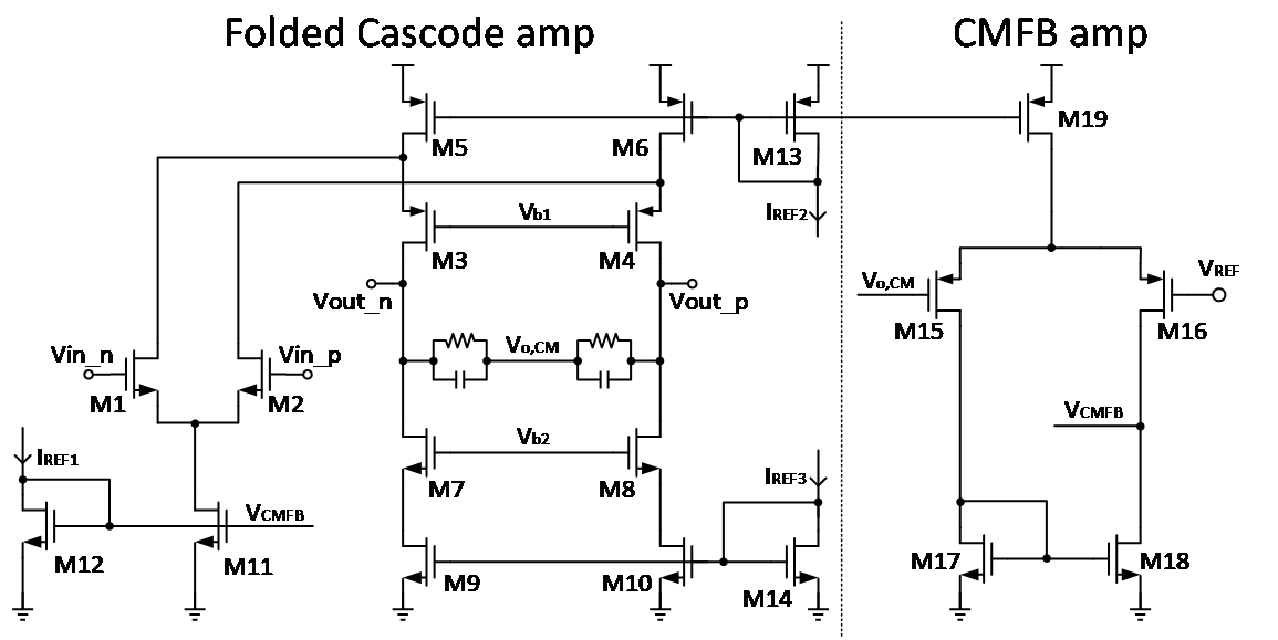
Figure 6. The structure of the core amplifier
To ensure stability, it is necessary to operate each MOS transistor in saturation region (equations 6):
\( {I_{D}}=\frac{1}{2}μ{C_{ox}}\frac{W}{L}{({V_{GS}}-{V_{TH}})^{2}}\ \ \ (6) \)
The ideal open-loop gain of this folded cascode structure without CMFB is (equations 7):
\( |{A_{V}}|={g_{m1}}\frac{({g_{m3}}{+g_{mb3}}){r_{O3}}(\frac{{r_{O1}}{r_{O5}}}{{r_{O1+}}{r_{O5}}})·({g_{m7}}{+g_{mb7}}){r_{O7}}{r_{O9}}}{({g_{m3}}{+g_{mb3}}){r_{O3}}(\frac{{r_{O1}}{r_{O5}}}{{r_{O1+}}{r_{O5}}})+({g_{m7}}{+g_{mb7}}){r_{O7}}{r_{O9}}}\ \ \ (7) \)
Theoretically, the open-loop gain can reach nearly 80dB. However, the CMRR falls far short of the requirement. After introducing the CMFB, although the gain decreases to 58dB, it is still sufficient to meet the amplification requirements for the signals.
2.5.CCIA Structure
The structure of the CCIA is shown in Figure 7(a). The input signal is modulated by\( {CH_{in}} \), converted into current by\( {C_{in}} \), then converted into voltage on\( {C_{f}} \), and finally demodulated back to the original frequency by\( {CH_{fb}} \)at the output as the amplified signal. The offset voltage and flicker noise of the OTA amplifier are modulated to high frequencies by\( {CH_{out}} \)and subsequently eliminated through LPF. The CCIA gain is determined by the capacitor ratio (equations 8):
\( {A_{V}}=\frac{{A_{0}}}{{A_{0}}+\frac{{C_{fb}}}{{C_{in}}}}=\frac{{C_{in}}}{{C_{fb}}}\ \ \ (8) \)

Figure 7. CCIA structure. (a) The structure of the instrumentation amplifier; (b) Programable capacitance of\( {C_{f}} \)
Due to the wide distribution of amplitude in bioimpedance, ranging from several microvolts to millivolts, the input capacitor needs to be programmatically adjustable to create a programmable gain amplifier, allowing for the collection of a wider range of biological signals, as shown in Figure 7(b). The buffer connected to the output is to suppress the influence of LPF shunt current and improve the input impedance of LPF.
3.Simulation Result
In this design, simulations were conducted using TSMC 180nm CMOS technology process with a power supply voltage of 3.3V. The overall current consumption of the CCIA is 45uA, resulting in a total power consumption of 0.15mW. The main OTA in the circuit was simulated, with the open-loop gain curve shown in Figure 8(a), revealing an open-loop gain of 58dB and a -3dB bandwidth of 8.2kHz, while the CMRR is 109dB. Figure 8(b) shows the OTA’s noise suppression capabilities, with PSRR+ of 102dB and PSRR- of 108dB.
|
(a) |
(b) |
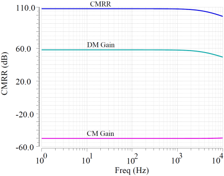
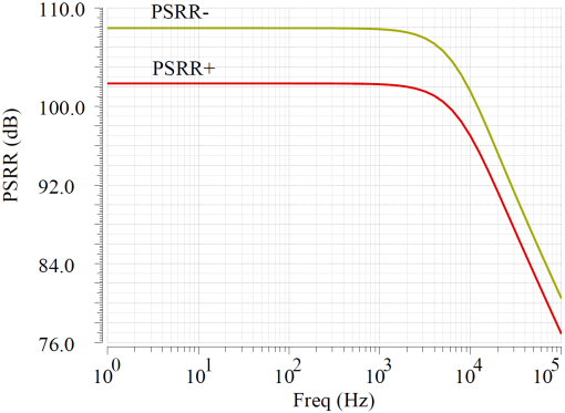
Figure 8. OTA performance simulation. (a) Gain and CMRR simulation result (b) PSRR simulation result
During the simulation of the CCIA, the chopping frequency was set to 5kHz. Figure 9(a) illustrates the importance of CMFB by comparing the cases with and without a CMFB amplifier. When there is no CMFB, the amplifier’s CMRR is only 50dB. This is because, in the absence of CMFB, due to the effects of transistor parameter mismatch, circuit layout, wiring, and other factors, common-mode signals can easily propagate and interfere, leading to an increase in common-mode gain, which in turn affects the value of CMRR. The transfer function of the CCIA is shown in Figure 9(b), and it can be seen that different transfer effects can be achieved when the input resistance\( {C_{in}} \)is set to different values.
|
(a) |
(b) |
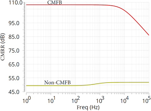
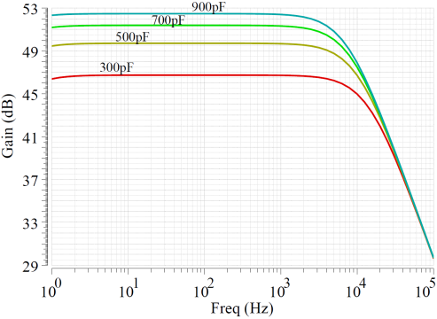
Figure 9. CCIA performance simulation. (a)CMFB simulation result; (b)Chopper simulation result
Table 2 compares the errors of the same bioimpedance model at different detection frequencies. By dividing the output voltage by the gain and\( {I_{CG}} \), the bioimpedance can be calculated. It can be observed that the system exhibits small errors, which increase with frequency. This is influenced by the amplifier bandwidth. However, the errors still meet the requirements.
Table 2. Comparison of bio-impedance detection
|
\( {BIOZ_{real}} \)(\( KΩ \)) |
\( {BIOZ_{detection}} \)(\( KΩ \)) |
Error |
|
|
10Hz |
846.73 |
825.31 |
2.53% |
|
100Hz |
157.18 |
153.03 |
2.53% |
|
1000Hz |
15.91 |
15.50 |
2.54% |
|
5000Hz |
3.18 |
3.09 |
2.83% |
4.Conclusion
In conclusion, the analog front-end designed in this paper employs a capacitively-coupled chopper instrumentation amplifier, with a core OTA utilizing a fully differentially folded cascode common source/common gate architecture and incorporating a CMFB loop to improve CMRR. The circuit was simulated using the TSMC 180nm technology, with a working voltage of 3.3V, a current consumption of 45uA, and a power consumption of 0.15mW. The core OTA achieved a maximum open-loop gain of 58dB and a -3dB bandwidth of 8.2KHz, with PSRR+ and PSRR- of 102dB and 108dB, respectively. While the CCIA’s CMRR could reach up to 109dB, the input impedance was reduced due to chopper modulation, which could be improved by incorporating positive feedback or other techniques in future work.
References
[1]. Ha, S., Kim, C., Chi, Y. M., Akinin, A., Maier, C., Ueno, A., & Cauwenberghs, G. (2014). Integrated circuits and electrode interfaces for noninvasive physiological monitoring. IEEE Transactions on biomedical engineering, 61(5), 1522-1537.
[2]. Webster, J. G. (Ed.). (2009). Medical instrumentation: application and design. John Wiley & Sons.
[3]. Zhang, S.F. (2021). Circuit Design Techniques for Integrated BioSignal Acquisition FrontEnds, University of Electrical Science and Technology of China.
[4]. Yazicioglu, R. F., Van Hoof, C., & Puers, R. (2008). Biopotential readout circuits for portable acquisition systems. Springer Science & Business Media.
[5]. Gao, C. (2020). Research and Design of Low Power Bio-signal Acquisition Analog Front-End. University of Electrical Science and Technology of China.
[6]. Burke, M. J., & Gleeson, D. T. (2000). A micropower dry-electrode ECG preamplifier. IEEE Transactions on Biomedical Engineering, 47(2), 155-162.
[7]. Pallas-Areny, R., & Webster, J. G. (1993). AC instrumentation amplifier for bioimpedance measurements. IEEE transactions on biomedical engineering, 40(8), 830-833.
[8]. Spinelli, E. M., Pallàs-Areny, R., & Mayosky, M. A. (2003). AC-coupled front-end for biopotential measurements. IEEE transactions on biomedical engineering, 50(3), 391-395.
[9]. Degrauwe, M., Vittoz, E., & Verbauwhede, I. (1985). A micropower CMOS-instrumentation amplifier. IEEE Journal of Solid-State Circuits, 20(3), 805-807.
[10]. Van Peteghem, P. M., Verbauwhede, I., & Sansen, W. M. C. (1985). Micropower high-performance SC building block for integrated low-level signal processing. IEEE journal of solid-state circuits, 20(4), 837-844.
[11]. Enz, C. C., & Temes, G. C. (1996). Circuit techniques for reducing the effects of op-amp imperfections: autozeroing, correlated double sampling, and chopper stabilization. Proceedings of the IEEE, 84(11), 1584-1614.
[12]. Toumazou, C., Lidgey, F. J., & Makris, C. A. (1989, February). Current-mode instrumentation amplifier. In IEE Colloquium on Current Mode Analogue Circuits (pp. 8-1). IET.
[13]. Harrison, R. R., & Charles, C. (2003). A low-power low-noise CMOS amplifier for neural recording applications. IEEE Journal of solid-state circuits, 38(6), 958-965.
[14]. Denison, T., Consoer, K., Santa, W., Avestruz, A. T., Cooley, J., & Kelly, A. (2007). A 2$\mu\hbox {W} $100 nV/rtHz Chopper-Stabilized Instrumentation Amplifier for Chronic Measurement of Neural Field Potentials. IEEE Journal of Solid-State Circuits, 42(12), 2934-2945.
[15]. Van Den Dool, B. J., & Huijsing, J. K. (1993). Indirect current feedback instrumentation amplifier with a common-mode input range that includes the negative roll. IEEE Journal of Solid-State Circuits, 28(7), 743-749.
[16]. Wu, R., Makinwa, K. A., & Huijsing, J. H. (2009). A chopper current-feedback instrumentation amplifier with a 1 mHz $1/f $ noise corner and an AC-coupled ripple reduction loop. IEEE Journal of Solid-State Circuits, 44(12), 3232-3243.
[17]. Ha, H., Sijbers, W., Van Wegberg, R., Xu, J., Konijnenburg, M., Vis, P., Breeschoten, V., Song, S., Van Hoof, C., & Van Helleputte, N. (2019). A bio-impedance readout IC with digital-assisted baseline cancellation for two-electrode measurement. IEEE Journal of Solid-State Circuits, 54(11), 2969-2979.
[18]. B. Razavi, Design of analog CMOS integrated circuits. Tsinghua University Press, 2005.
Cite this article
Mo,X.;Zhu,J.;Lu,H.;Liu,X. (2024). Design and simulation of a bioimpedance detection analog front-end targeting medical applications. Theoretical and Natural Science,39,112-120.
Data availability
The datasets used and/or analyzed during the current study will be available from the authors upon reasonable request.
Disclaimer/Publisher's Note
The statements, opinions and data contained in all publications are solely those of the individual author(s) and contributor(s) and not of EWA Publishing and/or the editor(s). EWA Publishing and/or the editor(s) disclaim responsibility for any injury to people or property resulting from any ideas, methods, instructions or products referred to in the content.
About volume
Volume title: Proceedings of the 2nd International Conference on Mathematical Physics and Computational Simulation
© 2024 by the author(s). Licensee EWA Publishing, Oxford, UK. This article is an open access article distributed under the terms and
conditions of the Creative Commons Attribution (CC BY) license. Authors who
publish this series agree to the following terms:
1. Authors retain copyright and grant the series right of first publication with the work simultaneously licensed under a Creative Commons
Attribution License that allows others to share the work with an acknowledgment of the work's authorship and initial publication in this
series.
2. Authors are able to enter into separate, additional contractual arrangements for the non-exclusive distribution of the series's published
version of the work (e.g., post it to an institutional repository or publish it in a book), with an acknowledgment of its initial
publication in this series.
3. Authors are permitted and encouraged to post their work online (e.g., in institutional repositories or on their website) prior to and
during the submission process, as it can lead to productive exchanges, as well as earlier and greater citation of published work (See
Open access policy for details).
References
[1]. Ha, S., Kim, C., Chi, Y. M., Akinin, A., Maier, C., Ueno, A., & Cauwenberghs, G. (2014). Integrated circuits and electrode interfaces for noninvasive physiological monitoring. IEEE Transactions on biomedical engineering, 61(5), 1522-1537.
[2]. Webster, J. G. (Ed.). (2009). Medical instrumentation: application and design. John Wiley & Sons.
[3]. Zhang, S.F. (2021). Circuit Design Techniques for Integrated BioSignal Acquisition FrontEnds, University of Electrical Science and Technology of China.
[4]. Yazicioglu, R. F., Van Hoof, C., & Puers, R. (2008). Biopotential readout circuits for portable acquisition systems. Springer Science & Business Media.
[5]. Gao, C. (2020). Research and Design of Low Power Bio-signal Acquisition Analog Front-End. University of Electrical Science and Technology of China.
[6]. Burke, M. J., & Gleeson, D. T. (2000). A micropower dry-electrode ECG preamplifier. IEEE Transactions on Biomedical Engineering, 47(2), 155-162.
[7]. Pallas-Areny, R., & Webster, J. G. (1993). AC instrumentation amplifier for bioimpedance measurements. IEEE transactions on biomedical engineering, 40(8), 830-833.
[8]. Spinelli, E. M., Pallàs-Areny, R., & Mayosky, M. A. (2003). AC-coupled front-end for biopotential measurements. IEEE transactions on biomedical engineering, 50(3), 391-395.
[9]. Degrauwe, M., Vittoz, E., & Verbauwhede, I. (1985). A micropower CMOS-instrumentation amplifier. IEEE Journal of Solid-State Circuits, 20(3), 805-807.
[10]. Van Peteghem, P. M., Verbauwhede, I., & Sansen, W. M. C. (1985). Micropower high-performance SC building block for integrated low-level signal processing. IEEE journal of solid-state circuits, 20(4), 837-844.
[11]. Enz, C. C., & Temes, G. C. (1996). Circuit techniques for reducing the effects of op-amp imperfections: autozeroing, correlated double sampling, and chopper stabilization. Proceedings of the IEEE, 84(11), 1584-1614.
[12]. Toumazou, C., Lidgey, F. J., & Makris, C. A. (1989, February). Current-mode instrumentation amplifier. In IEE Colloquium on Current Mode Analogue Circuits (pp. 8-1). IET.
[13]. Harrison, R. R., & Charles, C. (2003). A low-power low-noise CMOS amplifier for neural recording applications. IEEE Journal of solid-state circuits, 38(6), 958-965.
[14]. Denison, T., Consoer, K., Santa, W., Avestruz, A. T., Cooley, J., & Kelly, A. (2007). A 2$\mu\hbox {W} $100 nV/rtHz Chopper-Stabilized Instrumentation Amplifier for Chronic Measurement of Neural Field Potentials. IEEE Journal of Solid-State Circuits, 42(12), 2934-2945.
[15]. Van Den Dool, B. J., & Huijsing, J. K. (1993). Indirect current feedback instrumentation amplifier with a common-mode input range that includes the negative roll. IEEE Journal of Solid-State Circuits, 28(7), 743-749.
[16]. Wu, R., Makinwa, K. A., & Huijsing, J. H. (2009). A chopper current-feedback instrumentation amplifier with a 1 mHz $1/f $ noise corner and an AC-coupled ripple reduction loop. IEEE Journal of Solid-State Circuits, 44(12), 3232-3243.
[17]. Ha, H., Sijbers, W., Van Wegberg, R., Xu, J., Konijnenburg, M., Vis, P., Breeschoten, V., Song, S., Van Hoof, C., & Van Helleputte, N. (2019). A bio-impedance readout IC with digital-assisted baseline cancellation for two-electrode measurement. IEEE Journal of Solid-State Circuits, 54(11), 2969-2979.
[18]. B. Razavi, Design of analog CMOS integrated circuits. Tsinghua University Press, 2005.