


1. Introduction
Computational Fluid Dynamics (CFD) is a branch of fluid mechanics utilizing numerical methods to solve problems involving fluid flows [8]. CFD can be used to simulate the flow over a vehicle, heat flow in a manifold, and it can also be used to study circulatory and respiratory systems in the bio-medical industry [1]. Civil engineers use CFD tools to study the air flow around a structure that is going to be built. This is very important because a failure can occur if the structure isn’t able to withstand the aerodynamic load [8].
There haven’t been many researchers doing CFD on igloos because it is indeed quite a niche subject. One of which is a small group for researchers from Cornell. Although, instead of studying the air flow on the outside of an igloo, they studied the heat and air flow inside an igloo. In their project, they utilized a CFD software called GAMBIT and ran simulations to examine the temperature variation and airflow inside the igloo and analyzed to what extent does heat transfer through radiation in an igloo [5]. There are, however, much research done on the aerodynamic load experienced on structures other than igloos, such as houses. For example, Ozmen and his team studied wind flow over low-rise buildings with gabled roofs having different pitch angles. They investigated the relationship between turbulence kinetic energy profiles and the angle of the roof pitch [9]. The reason for this wide arrange of research done on aerodynamics of building is because how it closely relates to the safety of these structures. Especially nowadays, tall modern buildings can be extremely sensitive to wind because of their large surface area [2]. Though the scope of this research project isn’t as big as determining the safety of a skyscraper, it still gives a good insight how modern civil engineers are able to study the aerodynamics of buildings via CFD.
The main purpose of doing this project is to learn the primary principles of CFD and test out the methods learned from the experience on a real-world sample CFD case. The chosen applicable CFD case is a two-dimensional igloo placed under different wind flow angles. As mentioned, the scope of this experiment might not be as nearly as big as other researchers’ projects in the same field, it is enough for the purposes of this project which is learning more about the basic principles of CFD in COMSOL. Though it can be seen as short tutorial for people that haven’t used COMSOL before. It is enough to show someone how to design and simulate a 2D case in the software.
The first step of this project was to study a simple 2D cylinder case. The purpose of doing that is to get acquainted with the COMSOL software a little and learn how it works. After that, a sample NACA 0012 airfoil CFD case from COMSOL was studied. The documentation for this case is provided along with the CFD file on the COMSOL website. The purpose of this study is to see how a slightly more complex case on the software works and how to vary the angle of attack of this geometry. Finally, after the software is well understood, a real applicable CFD case could be studied. This was the igloo case, which is the eventual goal of the research. After setting up the simulation, the lift to drag ratio was studied. The lift divided by drag ratio is also called the L/D ratio. In the aerospace industry, the L/D ratio is also thought of as the aerodynamic efficiency factor of an aircraft [7]. For the purposes of this project, the lift and drag data is plotted onto on graph and the point where the ratio is closest to one and both lift and drag is closest to zero is determined. At this point, the aerodynamic load should be the lowest on the structure.
2. Methods
The application used was COMSOL Multiphysics. The software has many applications such as electrostatics and material engineering. In this project, COMSOL was used to simulating airflow around an igloo in a 2D flow. The airflow model used was the single-phase fluid in laminar flow model which is governed by the Navier-Stokes equations.
Before utilizing COMSOL for the actual project, some practice CFD cases had to be ran first to help with understanding the software.
2.1. D Cylinder Case
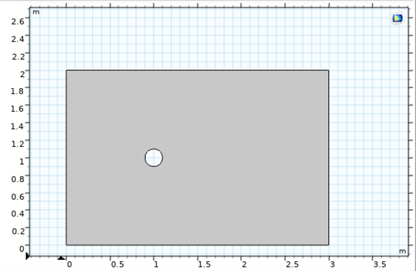
Figure 1. 2D Cylinder Geometry
The first CFD case is a simple 2D cylinder placed in a rectangular flow region. The geometry was made with a rectangle and a circle. Then, by utilizing the “difference” tool, the rectangle is punctured with the circle leaving a circular hole, as seen in figure 1.
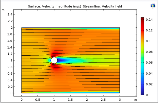
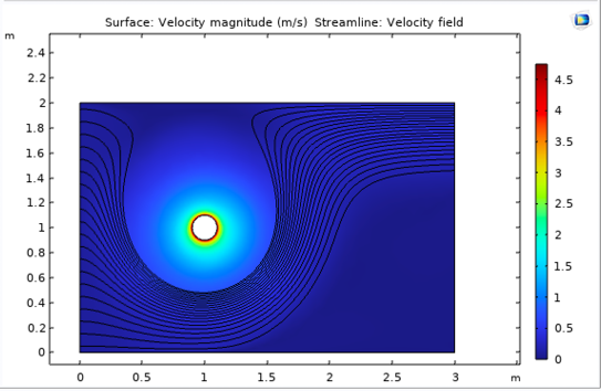
After that, an automatic mesh was generated. With that, the velocity and pressure fields were generated automatically by COMSOL. The velocity field can be seen in figure 2. Later on, a spin was also added to the cylinder. Under “Laminar Flow (spf)” menu, the wall condition of the cylinder could be modified so that it was rotating with a set angular velocity ω. Now, the rotation can be visualized in the updated velocity field (figure 3). In this situation, the cylinder is going to experience a magnus force due to the spin push it towards the direction of the spin.
|
|
Figure 2. 2D Cylinder Velocity Field | Figure 3. 2D Cylinder Velocity Field with Spin |
2.2. NACA 0012 Case
The COMSOL official website provides a CFD case studying the lift and drag of a sample NACA 0012 airfoil. In this CFD case, the geometry was created with a collection of parabolic curves. Then, a flow region is defined surrounding this airfoil geometry. In this case, the flow was defined using an SST turbulent flow model. A parametric sweep was utilized to change the angle of attack. Instead of changing the angle of attack of the airfoil itself, the researchers changed the inlet angle of the air flow. That way, it wouldn’t be necessary to rerun the entire simulation every time the angle of attack needs to be changed.
After studying this case by going through the research paper presented under this sample CFD case, parametric sweep of different angles of attack were altered to re-plot the curve for lift to show the angle where the airfoil stalls. However, the computer used for this task was simply not capable of finishing the calculations. Therefore, a new simulation had to be created where the air flow is set to a laminar flow model. That significantly shortened the time for the computer to finish the calculations.
|
|
Figure 4. NACA 0012 Geometry | Figure 5. NACA 0012 Velocity Field (AoA=14 deg) |
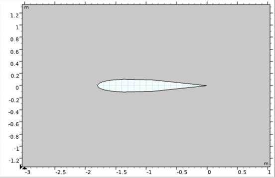
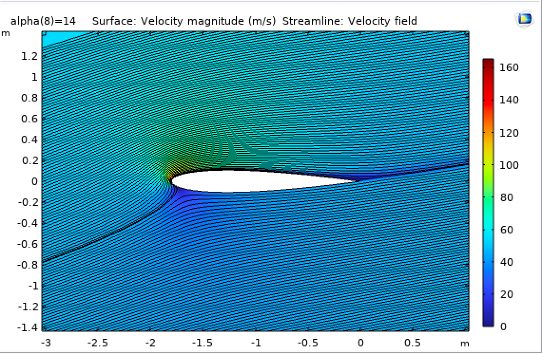
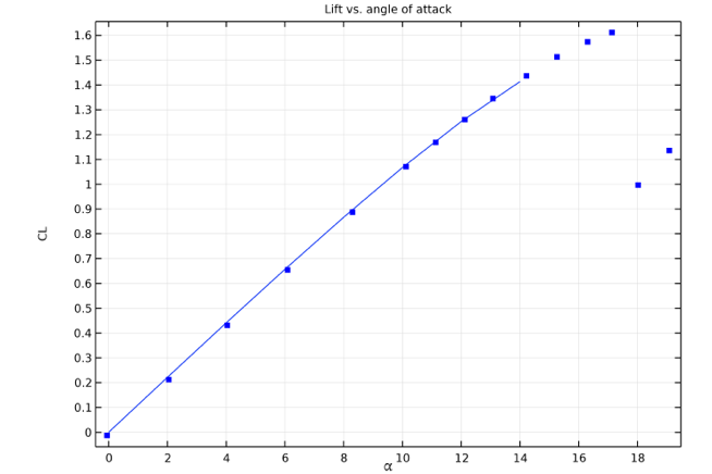
Figure 6. Lift vs. AoA for NACA 0012 (Credit: COMSOL)
As seen in figure 6, a lift versus angle of attack plot for the airfoil is shown. The blue line Is the lift coefficient calculated computationally using the SST turbulent model. The blue dots are the data collected experimentally using the lift data of Ladson. As seen in the plot, there is no significant discrepancies between the experimental and computational data. A significant drop in lift can be seen at around 17 degrees, and that is the angle where the airfoil stalls.
2.3. Igloo Case
Finally, after thoroughly studying the previous cases on COMSOL, it was time to start the simulation studying the main goal of this project.
To start, from the COMSOL modeling wizard, the 2D laminar flow model was chosen to give a general framework of how the simulation setup should go.
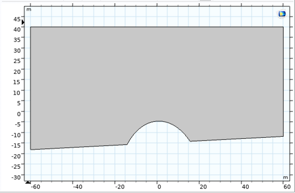
The geometry creation was done with the sketch and geometry tool in COMSOL as seen in figure 7. First, a 120m by 100m rectangle was created as the flow region. Then, using the Quadratic Bézier tool a dome shape was drawn. Connecting the two ends of the dome to another rectangle made the igloo be attached to ground instead of floating in the air. Now the second geometry looks like a rectangle with a bump in it. After that, the rotate function was used to make rotating the geometry with varying angle of attack easier. Finally, to create the actual flow region, the “Difference” tool made a cut on the first rectangle with the second geometry as a cutting tool complete the task. Now, the final geometry looks like a rectangle with a dome going inside of it at the bottom.
|
|
Figure 7. Geometry Creation for Igloo | Figure 8. Igloo Mesh |
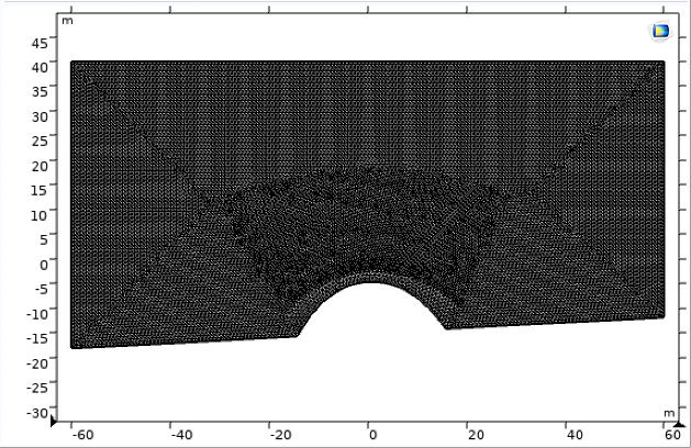
After the geometry has been built, it was time to define the laminar flow region. The velocity inlet was set as the left wall and velocity was set to 0.4 m/s. The pressure outlet was set as the right wall. Then, the other wall conditions (top, bottom, and igloo itself) were all set as slip. Lastly, the mesh can now be generated via the physics-controlled mesh tool and element size set as extremely fine.
Now, the study can be computed. The velocity field is generated automatically by COMSOL. The plots for 0, 9, 18, and 30 degree angles of attack are shown in figure 10.
The most important part of this process is the calculation of vertical and horizontal stress experienced by the igloo geometry. The line integration function in COMSOL was used to calculate them. The expressions used were “spf.T_stressx” and “spf.T_stressy”. They calculated the horizontal and vertical stress (or lift and drag) experienced by the igloo geometry. However, this is the stress experienced expressed in the up-right coordinate plane. The experimental goal is to calculate the stress in the coordinate plane in the igloo’s perspective. This means writing horizontal and vertical stress in the axis that are rotated by the angle of attack. The method used is shown below:
Drag = sin(⍺)(stress y) + cos(⍺)(stress x)
Lift = cos(⍺)(stress y) + sin(⍺)(stress x)
A quick sketch of the situation can be found in the figure below.
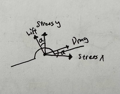
Figure 9. Rotated Coordinate Axis
3. Discussion
There were many challenges I faced when setting up the simulation. One of the most time-consuming issues I had to resolve was the “maximum Newton iterations reached” error when I ran the simulation. At first, I tried to refine the mesh by changing the “element size” option under “mesh”. That didn’t fix the issue even when I had it on the finest mesh setting. After that, I tried to change the inlet velocity of the simulation. I originally had it in 10 m/s and I reduced it to 0.4 m/s. However, the error persists. Finally, I tried to change the geometry. Since the dome shape was create with Quadratic Bézier, I reduced the height of the control point to decrease the height of the igloo. After that, COMSOL was able to finish the calculation and I finally obtained the velocity plot successfully. In future projects, I should consider using the “user-defined mesh” function to decrease mesh element size at points of interest (around the igloo) and also try making the geometry with less sharp corners.
Nowadays, civil engineers have to consider the effects of aerodynamic forces as houses and apartments are getting higher. A building can experience a large lateral from wind hitting the side of a building. They can also experience a large lift force depending on the wind angle and the shape of the building [6]. In areas near the poles, not only igloos do a well at providing warmth to inhabitants in the extreme cold temperature, but they can also be very effective at reducing the aerodynamic load experienced with its dome shape. There can be severe winter windstorms in the icy poles so this is very important.
4. Results
As seen in the velocity field plots shown in figure 10, there is a red region on the top of the igloo. The air flow velocity is shown on the right side as a spectrum for red is slowest and blue is fastest. The red region on top of the igloo shows an increase in velocity because of its curvature. In the bottom corners of the igloo, the velocity field is shown in blue meaning that it is relatively slow in the region. This can be interpreted that the pressure is the greatest in the corners of the igloo.
As seen in the angle of attack vs. drag & lift graph shown in figure 11, the data was collected from 0-30 angles of attack with 3-degree increments. There is a total of 11 data points for drag and lift. It can be observed from the graph that the drag experienced decreases as the wind blows from a higher position. This is intuitive because more component of the aerodynamic load is going onto the vertical axis, so there should be less drag at higher wind angles.
Consider the wind flowing through the geometry of the igloo at different angles as the igloo being built on different angles of ground surfaces, we can analyze at which angle approximately the igloo will likely to be experiencing the least aerodynamic load. Looking at the angle of attack versus drag and lift experienced from figure 11, it is quite obvious that the drag and lift curves intersect at one point where the angle of attack is approximately at 18 degrees. Therefore, we can say that at 18 degrees, the igloo will likely be experiencing the less aerodynamic load.
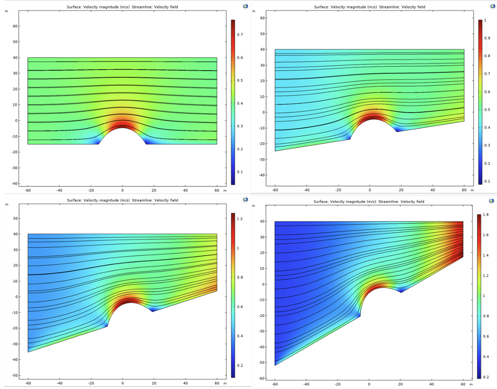
Figure 10. Velocity field with streamline for 0, 9, 18, 30 degree angles of attack
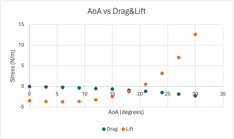
Figure 11. AoA vs. Drag & Lift
5. Conclusions
When an igloo is being built on a non-level surface or when the wind is moving at different angles, the structure will experience different aerodynamic loads. After CFD analysis of the lift and drag experienced by the structure at angles ranging from 0 to 30 degrees in 3-degree increments, the plot shows that the lift and drag curves are intersecting at around 18 degrees and it is also when both of them are closest to zero. Therefore, it can be concluded that the igloo structure sample will likely to be experiencing the least aerodynamic load when it is built on an angle of approximately 18 degrees.
References
[1]. Bhaskaran, Rajesh and Collins, Lance. “Introduction to CFD Basics.” Cornell.
[2]. Baghaei Daemei, Abdollah, et al. “Study on wind aerodynamic and flow characteristics of triangular-shaped tall buildings and CFD simulation in order to assess drag coefficient.” Ain Shams Engineering Journal, vol. 10, no. 3, Sept. 2019, pp. 541–548, https://doi.org/10.1016/j.asej.2018.08.008.
[3]. C.L. Ladson, “Effects of Independent Variation of Mach and Reynolds Numbers on the Low-Speed Aerodynamic Characteristics of the NACA 0012 Airfoil Section, ” NASA TM 4074, 1988.
[4]. “Flow Around an Inclined NACA 0012 Airfoil.” COMSOL.
[5]. Holihan, Rich, et al. “How Warm is the Igloo.” Cornell. 2003.
[6]. Khaled, Md Faiaz, and Aly Mousaad Aly. “Assessing aerodynamic loads on low-rise buildings considering Reynolds number and turbulence effects: A Review.” Advances in Aerodynamics, vol. 4, no. 1, 1 June 2022, https://doi.org/10.1186/s42774-022-00114-0.
[7]. “Lift to Drag (L/D) Ratio.” NASA, NASA, 21 Jan. 2023, www1.grc.nasa.gov/beginners-guide-to-aeronautics/lift-to-drag-l-d-ratio/#:~:text=The%20lift%20divided%20by%20drag, a%20given%20change%20in%20height.
[8]. Sultana, Asma & Sultana, Qamar. (2021). Application of Computational Fluid Dynamics in Civil Engineering-A Review. International Journal of Current Engineering and Technology. 1984-1987.
[9]. Y. Ozmen, E., et al. “Wind flow over the low-rise building models with gabled roofs having different pitch angles.” Building and Environment, Pergamon.Volume 95, 2016, Pages 63-74, ISSN 0360-1323.
Cite this article
Wu,P. (2024). The aerodynamic load experienced by an igloo under varying wind angles. Theoretical and Natural Science,55,1-7.
Data availability
The datasets used and/or analyzed during the current study will be available from the authors upon reasonable request.
Disclaimer/Publisher's Note
The statements, opinions and data contained in all publications are solely those of the individual author(s) and contributor(s) and not of EWA Publishing and/or the editor(s). EWA Publishing and/or the editor(s) disclaim responsibility for any injury to people or property resulting from any ideas, methods, instructions or products referred to in the content.
About volume
Volume title: Proceedings of the 2nd International Conference on Applied Physics and Mathematical Modeling
© 2024 by the author(s). Licensee EWA Publishing, Oxford, UK. This article is an open access article distributed under the terms and
conditions of the Creative Commons Attribution (CC BY) license. Authors who
publish this series agree to the following terms:
1. Authors retain copyright and grant the series right of first publication with the work simultaneously licensed under a Creative Commons
Attribution License that allows others to share the work with an acknowledgment of the work's authorship and initial publication in this
series.
2. Authors are able to enter into separate, additional contractual arrangements for the non-exclusive distribution of the series's published
version of the work (e.g., post it to an institutional repository or publish it in a book), with an acknowledgment of its initial
publication in this series.
3. Authors are permitted and encouraged to post their work online (e.g., in institutional repositories or on their website) prior to and
during the submission process, as it can lead to productive exchanges, as well as earlier and greater citation of published work (See
Open access policy for details).
References
[1]. Bhaskaran, Rajesh and Collins, Lance. “Introduction to CFD Basics.” Cornell.
[2]. Baghaei Daemei, Abdollah, et al. “Study on wind aerodynamic and flow characteristics of triangular-shaped tall buildings and CFD simulation in order to assess drag coefficient.” Ain Shams Engineering Journal, vol. 10, no. 3, Sept. 2019, pp. 541–548, https://doi.org/10.1016/j.asej.2018.08.008.
[3]. C.L. Ladson, “Effects of Independent Variation of Mach and Reynolds Numbers on the Low-Speed Aerodynamic Characteristics of the NACA 0012 Airfoil Section, ” NASA TM 4074, 1988.
[4]. “Flow Around an Inclined NACA 0012 Airfoil.” COMSOL.
[5]. Holihan, Rich, et al. “How Warm is the Igloo.” Cornell. 2003.
[6]. Khaled, Md Faiaz, and Aly Mousaad Aly. “Assessing aerodynamic loads on low-rise buildings considering Reynolds number and turbulence effects: A Review.” Advances in Aerodynamics, vol. 4, no. 1, 1 June 2022, https://doi.org/10.1186/s42774-022-00114-0.
[7]. “Lift to Drag (L/D) Ratio.” NASA, NASA, 21 Jan. 2023, www1.grc.nasa.gov/beginners-guide-to-aeronautics/lift-to-drag-l-d-ratio/#:~:text=The%20lift%20divided%20by%20drag, a%20given%20change%20in%20height.
[8]. Sultana, Asma & Sultana, Qamar. (2021). Application of Computational Fluid Dynamics in Civil Engineering-A Review. International Journal of Current Engineering and Technology. 1984-1987.
[9]. Y. Ozmen, E., et al. “Wind flow over the low-rise building models with gabled roofs having different pitch angles.” Building and Environment, Pergamon.Volume 95, 2016, Pages 63-74, ISSN 0360-1323.