


1. Introduction
The application of tail wing technology in racing has been very extensive. The tail wing is one of the most important components of the aerodynamic package in racing cars, responsible for providing down force to the car, ensuring that the car can have sufficient ground grip, and preventing risks during high-speed movement. And during the rapid movement of the racing car, due to the sudden appearance of an empty area behind the car, the airflow will show a turbulent vortex shape and form a low-pressure area, while the front of the racing car is under normal pressure, which will create a large air resistance. The tail wing (and diffuser) is used to quickly smooth out the turbulent flow.
In addition, in the field of racing, in recent years, civilian ordinary cars have also attached increasing importance to the use of tail wing components. Currently, automobile manufacturers around the world are committed to researching and developing new technologies for automotive drag, and a more rational, perfect, and scientific era of tail fins has arrived. In the past, China neglected the installation of the rear wing in the use of sedans because the speed was not high at that time, and the drag reduction and fuel saving effects of the rear wing were not very obvious. If driving at a speed of 120km/h on the highway, it can save 14% fuel, and the role of the car's rear wing is very obvious. A rear wing made by precise calculation based on the width of the vehicle body can not only make the vehicle more stable and safe during high-speed driving, but also reduce air resistance, increase speed, and save fuel consumption. This has certain positive significance for energy conservation and environmental protection in the current situation of high oil prices and energy shortages.
2. Relevant Academic Research
There have been some researchers who have carried out related work on the tail wing of racing cars, such as Zhejiang University of Technology conducting wind tunnel and numerical simulation studies on FSAE racing cars. Aerodynamic analysis and comparison were conducted on airfoils that have a significant impact on the aerodynamic performance of the tail wing under different curvature and curvature position conditions. The effects of wing curvature and thickness on its drag and negative lift were discovered, and suitable airfoils for FSAE racing tail wings were determined; At the same time, key parameters such as the wing gap, end plate shape, and number of fins of the tail wing were studied, and the optimal solution was determined based on the variation laws and matching principles of its pressure cloud map and streamline map. Researchers at Harbin Institute of Technology used computational fluid dynamics (CFD) method and boundary element method based on potential flow theory to solve the flow around a two-dimensional airfoil profile NACA0015. [1]Researchers from Chongqing University combined the wing shape analysis software Profili and Xfoil to conduct detailed airfoil selection and angle of attack determination. Three dimensional flow field numerical simulation based on computational fluid dynamics was used to optimize the front and rear wings of the racing car[2].After comparing various styling strategies, a new type of drag reducing curved wing design was determined, using an aerodynamic kit consisting of a "straight main flap" tail wing and an arrow shaped curved front wing. The optimized racing car has an increased negative lift coefficient of 1.68 and a negative lift to drag ratio of 1.91.[3]
3. Methods
In research, both experimental and simulation methods are commonly used to carry out related research work. This article uses Ansys Fluent commercial numerical simulation software as the main research tool to design the tail structure and calculate the aerodynamic performance of four different airfoils: NACA4412, NACA63A210, NACA23012, and NACA23015. By analyzing the simulation results, the optimal tail wing structure was obtained, and the laws of downforce and drag changing with velocity and angle of attack were given.
3.1. Detailed Approach
The four types of airfoils used in this article are NACA4412, NACA63a210, NACA23012, and NACA23015. The NACA airfoil is a series of low-speed airfoil models introduced by NASA in the United States. The cross-sections of the four selected airfoils in this article are shown in Figure 1.
NACA.airfoil.63a210
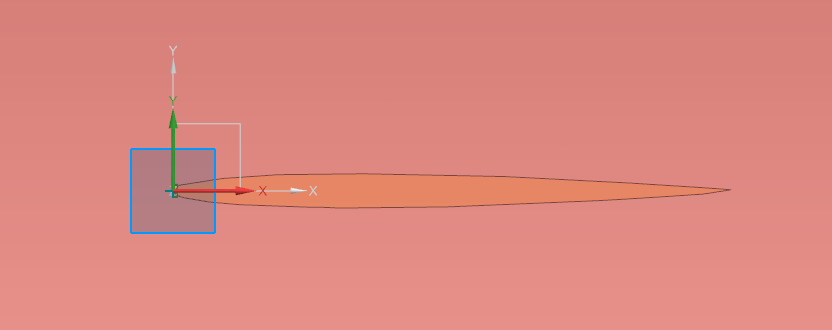
(b)NACA.airfoil.4412
(c)NACA.airfoil.23012
(d)NACA.airfoil.23015
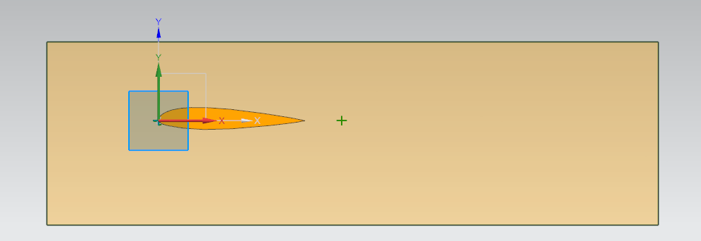
Figure 1. The cross-sections of the four selected airfoils’Drawing
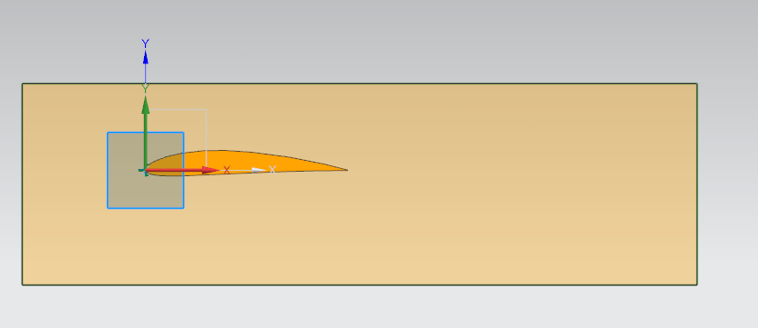
Using cross-sectional point cloud data from the airfoil database for modeling, polynomial fitting curves were applied to the upper and lower wing surfaces to obtain actual wing surface curves. Then, a three-dimensional model of the actual tail wing was obtained by stretching. By raising the middle position of the tail wing, a three-dimensional shaped tail wing can be formed, which can improve the pressure distribution in its middle section and increase the downforce of the tail wing[4],as shown in Figure 2.
(a)NACA.airfoil.63a210
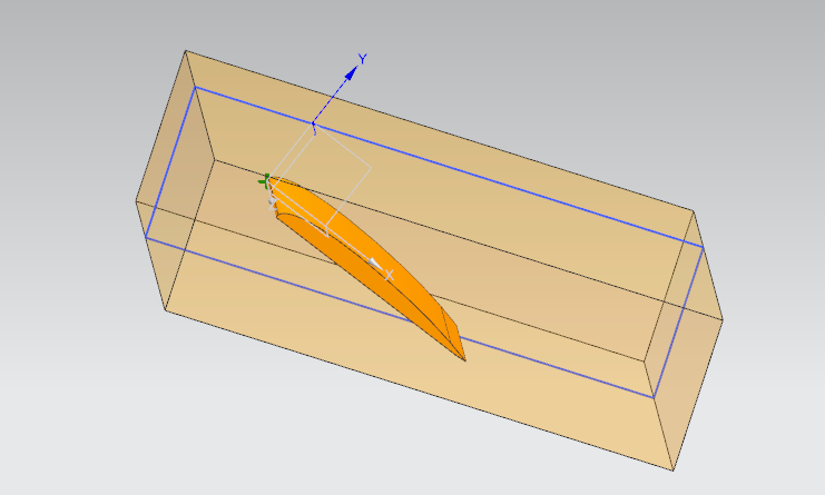
(b)NACA.airfoil.4412
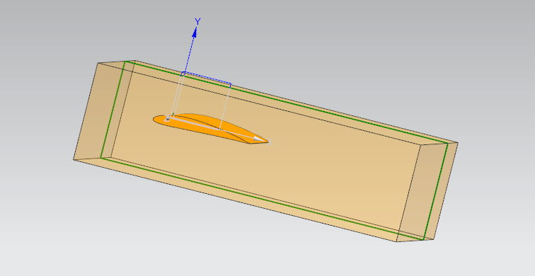
(c)NACA.airfoil.23012
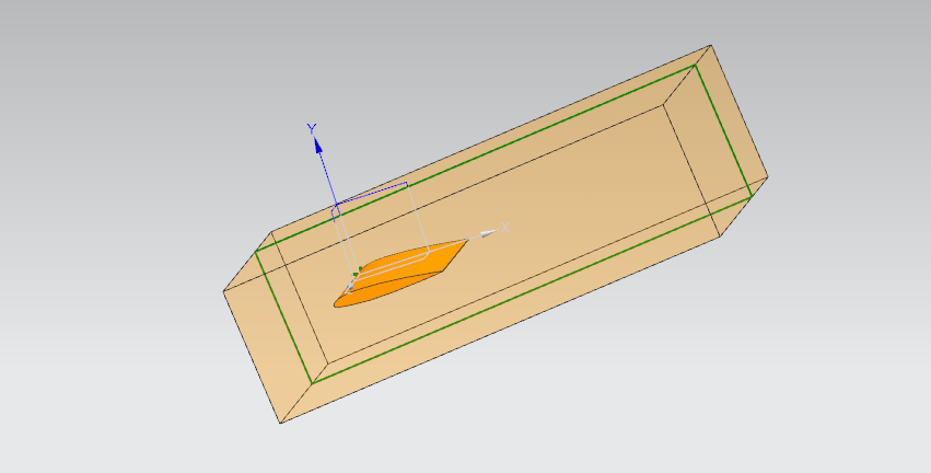
(d)NACA.airfoil.23015
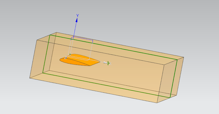
Figure 2. Three dimensional image obtained after stretching the airfoil
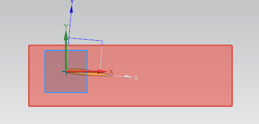
For different 3D models of airfoils, the same numerical calculation domain is used, and the setting of the numerical calculation domain generally follows the principle of "two in the front and five in the back, three in the top and three in the bottom". The overall calculation domain size is 80cm * 40cm * 120cm, as shown in Figure 3.
The calculation method for numerical simulation of flow fields generally adopts the method of solving N-S equations. However, in the actual solving process, due to the strong nonlinearity of N-S equations, direct numerical solution is difficult. Therefore, commercial numerical simulation software Ansys Fluent is used as the solver, and the Reynolds stress averaging method is used to solve turbulence, thereby obtaining more reliable flow field simulation results.
Use the steady-state pressure based solver in Fluent to solve the problem, with velocity boundary conditions at the inlet and pressure boundary conditions (atmospheric pressure) at the outlet. The total number of grids is 2.5 million, and the coupled algorithm is used. The turbulence model uses the SST k-omega method. Convergence criterion 1e-6
4. Experimental Result
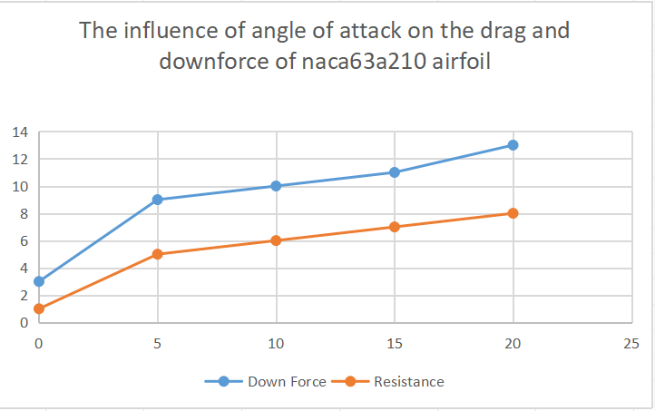
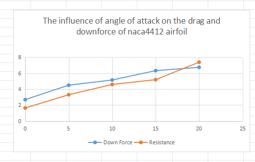
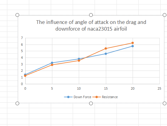
Calculation results and analysis. Firstly, specify the benchmark operating conditions for 4 types of airfoils, plan to calculate 50m/s, and then calculate 5 attack angles of 0 °, 5 °, 10 °, 15 °, and 20 °.[5] A total of 20 types of data need to be calculated. Statistical cloud map for each operating condition, including pressure and resistance, can be compiled into a table. Draw a graph based on the obtained data.
[a]NACA.airfoil.63a210
[b]NACA.airfoil.4412
[c]NACA.airfoil.23015
[d]NACA.airfoil.23012
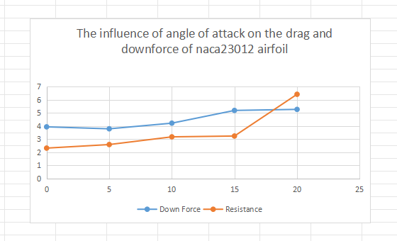
Figure 3. Down force and Resistance
As can be seen from Fig. 3, the downforce and resistance of the four wings increase with the angle of attack. But the trends are different for each. Detailed results please see the sixth point of this paper: Data Analysis
5. Conclusion
After modeling and numerical simulation of different wing structures, the following conclusions can be obtained:
(1) Quantitative conclusions should be used as much as possible. Within the speed range studied in this article, both downforce and drag increase with increasing speed, while drag and downforce increase with increasing angle of attack.
(2) The comparison results between different airfoils show that at a constant speed, the NACA23012 airfoil has the highest lift to drag ratio within 0 to 15 °, which can provide greater downforce while minimizing drag. Therefore, it is believed that the airfoil structure selection within 0 to 15 ° is the best. The NACA63A210 airfoil has the highest lift to drag ratio at 0 °, which is the optimal structural choice for the same airfoil with different angles of attack. The NACA4412 airfoil has the highest lift to drag ratio at 10 °, so the optimal structural choice for this wing is 10 °. When the angle of attack of NACA23012 is 15 °, there is a maximum lift to drag ratio. When the angle of attack of the NACA23015 airfoil is 5 °, there is a maximum lift to drag ratio.
References
[1]. Yu Kainan, Xie Shibin. Research on CFD based FSAE racing tail design and optimization [J]. Mechanical and Electrical Engineering, 2018, 35 (01): 16-21.
[2]. Cheng Jie, Fang Zheng, Zhang Wei. Comparative study of CFD and potential flow numerical simulation methods for the flow field around wing profiles [J]. Hydrodynamics Research and Progress Series A, 2023, 38 (05): 677-682. DOI: 10.16076/j.cnki. cjhd.2023.05.004
[3]. Zhou Tao, Zeng Zhong Aerodynamic Optimization Design of FSAE Racing New Curved Front Wing and Tail Wing [J]. Journal of Chongqing University, 2017, 40 (10): 40-52
[4]. Tian Tian, Li Gang, Zhang Zhiqiang, etc FSAC racing car body empty sleeve design and simulation analysis [J]. Journal of Liaoning University of Technology (Natural Science Edition), 2023, 43 (04): 221-227. DOI: 10.15916/j.issn1674-3261.2021.04.003
[5]. Zhang Yingchao, Jiang Qingwen, Gong Hongyu, et al. The mutual influence between the tail wing and aerodynamic characteristics of a racing car [C]//China Society of Automotive Engineers.Automotive Aerodynamics Committee of China SAE. Proceedings of the 2022 Academic Annual Meeting of the Automotive Aerodynamics Committee of the Chinese Society of Automotive Engineers - Aerodynamics Venue. State Key Laboratory of Automotive Simulation and Control, Jilin University;, 2022:13.DOI:10.26914/c.cnkihy.2022.035139.
Cite this article
Liu,W. (2024). Using numerical simulation methods to analyze the aerodynamic performance of racing tail fins under multiple factor conditions. Theoretical and Natural Science,55,54-60.
Data availability
The datasets used and/or analyzed during the current study will be available from the authors upon reasonable request.
Disclaimer/Publisher's Note
The statements, opinions and data contained in all publications are solely those of the individual author(s) and contributor(s) and not of EWA Publishing and/or the editor(s). EWA Publishing and/or the editor(s) disclaim responsibility for any injury to people or property resulting from any ideas, methods, instructions or products referred to in the content.
About volume
Volume title: Proceedings of the 2nd International Conference on Applied Physics and Mathematical Modeling
© 2024 by the author(s). Licensee EWA Publishing, Oxford, UK. This article is an open access article distributed under the terms and
conditions of the Creative Commons Attribution (CC BY) license. Authors who
publish this series agree to the following terms:
1. Authors retain copyright and grant the series right of first publication with the work simultaneously licensed under a Creative Commons
Attribution License that allows others to share the work with an acknowledgment of the work's authorship and initial publication in this
series.
2. Authors are able to enter into separate, additional contractual arrangements for the non-exclusive distribution of the series's published
version of the work (e.g., post it to an institutional repository or publish it in a book), with an acknowledgment of its initial
publication in this series.
3. Authors are permitted and encouraged to post their work online (e.g., in institutional repositories or on their website) prior to and
during the submission process, as it can lead to productive exchanges, as well as earlier and greater citation of published work (See
Open access policy for details).
References
[1]. Yu Kainan, Xie Shibin. Research on CFD based FSAE racing tail design and optimization [J]. Mechanical and Electrical Engineering, 2018, 35 (01): 16-21.
[2]. Cheng Jie, Fang Zheng, Zhang Wei. Comparative study of CFD and potential flow numerical simulation methods for the flow field around wing profiles [J]. Hydrodynamics Research and Progress Series A, 2023, 38 (05): 677-682. DOI: 10.16076/j.cnki. cjhd.2023.05.004
[3]. Zhou Tao, Zeng Zhong Aerodynamic Optimization Design of FSAE Racing New Curved Front Wing and Tail Wing [J]. Journal of Chongqing University, 2017, 40 (10): 40-52
[4]. Tian Tian, Li Gang, Zhang Zhiqiang, etc FSAC racing car body empty sleeve design and simulation analysis [J]. Journal of Liaoning University of Technology (Natural Science Edition), 2023, 43 (04): 221-227. DOI: 10.15916/j.issn1674-3261.2021.04.003
[5]. Zhang Yingchao, Jiang Qingwen, Gong Hongyu, et al. The mutual influence between the tail wing and aerodynamic characteristics of a racing car [C]//China Society of Automotive Engineers.Automotive Aerodynamics Committee of China SAE. Proceedings of the 2022 Academic Annual Meeting of the Automotive Aerodynamics Committee of the Chinese Society of Automotive Engineers - Aerodynamics Venue. State Key Laboratory of Automotive Simulation and Control, Jilin University;, 2022:13.DOI:10.26914/c.cnkihy.2022.035139.