


1 Introduction
When watching bicycle road-racing events such as the Tour de France, it is a common phenomenon to see racers form lines while riding, with the following riders always riding almost directly behind the leader when possible. Similar techniques are used in car-racing and motorcycle-racing events such as Formula one and Moto-GP, when racers would follow their opponents on straights. Such a technique is called ‘drafting’ by the commentators, and racers implement this trick in hopes for reducing the drag incurred from the air by following the bicycle, car or motorcycle in front and taking advantage of the void in the space occupied by the leader a moment ago. Real-life data has shown that this technique can enable the racers to reach higher speeds and save energy, but it gives no indication as to to what extent is the method effective, and under what circumstances. Therefore, I decided to study the fundamental theory behind this phenomenon by studying the wake past two 2D ellipses in order. By changing their separation and the angle between the line connecting them and the direction of the flow, the effect of ‘drafting’ under different circumstances and the underlying physical mechanisms are carefully explored.
There has been extensive studies made on the flow past a single cylinder. It has been pointed out that at Re<5 , symmetrical vortex ring is generated in the wake without laminar separation. At Re=48 , the steady flow transmutes to an unsteady one, forming Karman vortex shedding patterns with two streets of vortices which shed alternately in opposite directions.
For circumstances with high reynolds numbers, different patterns are observed. At Re=140,000 , the wake pattern evolves to display greater random secondary vortex shedding and recirculation in the far-wake section.[1] When Re increases past the critical regime to 8.5×10⁵ , the flow evolves from asymmetrical to stable symmetrical in the super-critical regime.[2] The stable flow has a drag coefficient of Cd≈0.22 , with a vortex shedding frequency of St≈0.44 , a sharp increase from the critical regime.
The vortex shedding pattern behind a single elliptic cylinder depends on the aspect ratio of the cylinder, χ ( χ=a/b , where a, b are the lengths semi-major axis and semi-minor axis, respectively), and the angle of attack, θ . It is observed that at Re=150 , the wake of an elliptic cylinder display steady wake ( χ<0.37 , θ<2.5∘ ), Karman vortex shedding pattern followed by steady wake ( 0.37≤χ≤0.67 ) and Karman vortex shedding pattern followed by secondary wake ( χ≤0.67 , θ>52∘ ).[3] Overall, the laminar separation takes place at greater reynolds number for cylinders with greater aspect ratio and smaller angle of attack. For the flow past a single elliptic cylinder, at Re=200 , the primary shedding frequency reduces as the angle of attack increases for cylinders of the same aspect ratio.[4] The drag coefficients increase with θ . The lift coefficients first increase with θ and then decreases.
For two cylinders in tandem, extensive studies have been conducted for the wake behind circular cylinders. For example, Taneda et al. reported that discontinuous vortex shedding can be observed for 4.5<s/d<5 at Re=100 , 3.5<s/d<4 at Re=300 and 3<s/d<3.5 at Re=103 with suppressed vortex shedding.[5] It is commonly observed that the flow pattern shifts when the spacing approaches a critical value, which is around 3.5 times the diameter of the cylinder.[6] The trailing cylinder located within or close to the recirculation zone would suppress the wake of the leading cylinder. The wakes become independent beyond this critical level. For two elliptic cylinders in tandem, a different unstable state is observed as an accumulation of primary and secondary vortex shedding modes. For multiple cylinders in tandem at low Reynolds numbers of Re=65−160 , two vortex shedding frequencies for downstream cylinders form due to significant wake interference.[7] The transition between primary shedding patterns and secondary shedding patterns is observed at greater Reynolds numbers.
Based on these previous work, it can be observed that a kinetic study on the wake patterns of tandem elliptical cylinders at high Reynolds numbers is limited, with the effect of θ yet to be discussed. To address these knowledge gaps, this research is designed to answer the following two critical questions:
1 How do the separation spacing and the azimuthal angle affect the turbulent wake dynamics behind two elliptic cylinders placed closely?
2 How do the separation spacing and the azimuthal angle affect the aerodynamic coefficients behind two elliptic cylinders placed closely?
2 Mathematical modeling and numerical formulation
2.1 Governing equations for RANS
The wind flow incident on the cylinders is assumed to be incompressible and isothermal. The neutral atmospheric boundary layer is considered, and the governing equations regarding conservation of mass and momentum of air are as follows:
∂¯Ux∂xi=0 (1)
¯Uj∂¯Ux∂xi=−1ρ∂¯P∂xi+∂∂xj(μ∂¯Ux∂xj)+∂(−¯U′iU′j)∂xi∂xj (2)
Where ¯Ui(i=x,y,z) represents the mean velocity tensor, xi is the Cartesian coordinate, ¯P,ρ and μ are the pressure, air density and kinematic viscosity. −¯U′iU′j is the Reynolds stress, which is modeled below as:
−¯U′iU′j=μt(∂¯Uj∂xi+∂¯Ui∂xj)−2kδij3 (3)
Here, μt is the turbulent kinematic viscosity, k and δij are the turbulent kinetic energy (TKE) and the Kronecker delta, respectively. The standard k−ϵ turbulence model is applied:
∂∂xi[∂k∂xi(μ+μtσk)]−ϵ+Pkρ=¯Ui∂k∂xi (4)
∂∂xi[∂ϵ∂xi(μ+μtσk)]−Cϵ2ϵ2k+ϵCϵ1ρk(Cϵ3Gb+Pk)=¯Ui∂ϵ]∂xi (5)
2.2 Problem establishment
Due to the lack in studies on wake patterns behind elliptic cylinders in tandem at high Reynolds number, and relating to the bicycle rider situation, the flow past two ellyptic cylinders in tandem is studied, with the cylinders having width of 0.5m and height of 1.8m , similar to the parameters of a rider on a bicycle. The flow velocity is opted to be 12.5m/s , a rough value of bicycle speed during road racing. The separation to semi-major-axis ratio is used to describe the separation between the two riders, and values S/a=2.2,3,4,8,12 are opted. The azimuthal angle, or the angle between the common major axis of the two cylinders and the flow direction is chosen to be θ=0,30∘,45∘ . Table 1 is a table of the variables.
Table 1. Parameters of the present cases.
Parameter | Value |
separation to semi-major-axis ratio ( S/a ) | 2.2,3,4,8,12 |
azimuthal angle ( θ ) | 0,30∘,45∘ |
major axis ( 2a ) | 1.8m |
minor axis ( 2b ) | 0.5m |
inlet velocity ( U ) | 12.5m/s |
2.3 Computational domain and boundary conditions
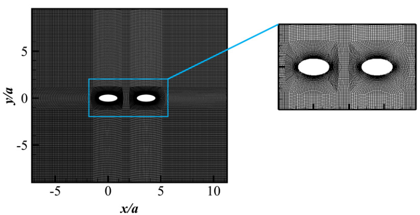
Figure 1. Illustration of the grid used in the present work.
The Navier–Stokes equations have been solved in the computational domain sketched in figure 1. In the present work, the aspect ratio χ of the elliptic cylinder is taken as 2a/2b=1.8m:0.5m . The origin of the coordinate system is fixed at the bottom of the inlet. The x− and y -axis represent the streamwise and wall normal directions respectively. The long axis of the cylinders are in the x -axis, or streamwise direction. Free-slip boundary conditions are imposed on the two walls, to simulate an infinitely spanning space. A uniform velocity boundary condition is prescribed at the inlet boundary, and a pressure boundary condition is imposed at the outlet boundary. The surface of the cylinders are set with no-slip conditions. A hexahedral mesh with an O-grid topology is generated for all cases using the commercial grid generation software ANSYS Meshing (ANSYS Inc., 2023). The mesh is refined near the cylinders and the near wake, to capture the turbulent structures, as shown in figure 1.
2.4 Grid independence study
To study the grid independence, three sets of grids are tested for the configuration of two elliptical cylinders in tandem with S/a =14 and Re=ρU0aμ=7.725⋅105 . The total number of the grid cells for the Coarse, Standard, and Fine grids are 5,922, 124,480, and 494,957, respectively. The number of points on the circumference of the elliptical cylinder surface are 36, 40, and 60 respectively. Table 2 summarizes the time-averaged drag coefficients of the leading cylinder ( Cd1 ), the trailing cylinder ( Cd2 ), and the cylinders as a whole ( Cd ). It is found that the difference between the results of the Standard and Fine grids is lower than 0.55%. Therefore, the Standard grid is thought to be sufficient.
Table 2. Comparisons of the time-averaged drag coefficients for three sets of grids.
mesh | total number of cells | number of nodes on the circumference of cylinder | Cd1 | Cd2 | Cd |
coarse | 5922 | 36 | 0.031862 | 0.039034 | 0.070897 |
moderate | 124480 | 40 | 0.052079 | 0.05466 | 0.10673 |
fine | 494957 | 60 | 0.056098 | 0.064395 | 0.12048 |
3 Wake dynamics behind two elliptic cylinders
The wake dynamics behind the two elliptic cylinders as well as the change of force coefficients experienced by the two cylinders over time are examined. The wake regimes are classified based on: (1) wake structures characterized by contours of Q -function[8]; (2) contours of velocity and TKE; (3) time histories of drag and lift coefficients and the corresponding frequency spectra. The wake states identified for the present parameter space of ( S/a , θ ) can be divided into six categories: (I) Wake states without vortex shedding (WOVS); (II) Single bluff body wake (SBB); (III) Suppressed vortex shedding (SVS); (IV) Coupled vortex shedding (CVS); (V) Anti-phase vortex shdding (AVS); (VI) In-phase vortex shedding (IVS).
3.1 Wake states without vortex shedding
Steady-state flow regimes without vortex shedding have been identified for S/a=2.2 at θ=0∘ and 30∘ , as well as for S/a=8 and 12 at θ=0∘ . The corresponding wake patterns for the representative cases of S/a=2.2 , θ=30∘ and S/a=8 , θ=0∘ are illustrated in Figure 2.
Figures 2 (a) and 2 (b) depict the wake structures characterized by vorticity magnitude contours for the cases of S/a=2.2 , θ=30∘ and S/a=8 , θ=0∘ , respectively. As shown in Figures 2 (c) and2 (d), no vortex shedding occurs for these cases. The flow regime is thus classified as the "wake state without vortex shedding" (WOVS).
The turbulent kinetic energy (TKE), which reflects the intensity of turbulent fluctuations in the flow field, is presented in Figures 2 (e) and 2 (f) for S/a=2.2 , θ=30∘ , and S/a=8 , θ=0∘ , respectively. In both cases, elevated TKE is observed in the shear layer, gradually dissipating downstream. Notably, the TKE for the case of S/a=2.2 and θ=30∘ is significantly higher than that for S/a=8 , θ=0∘ .
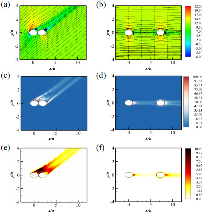
Figure 2. Wake characterizations for the WOVS state: (a, b) Contours of x− velocity in the xoz− plane with in-plane streamlines, (c, d) contours of vorticity magnitude, and (e, f) contours of TKE. (a, c, e) represent for the case with S/a=2.2 and θ=30∘ , and (b, d, f) for the case with S/a=8 and θ=0∘ .
3.2 Single bluff body wake
When the two elliptic cylinders are placed very close to each other, such as in the cases of S/a=2.2 , θ=45∘ and S/a=4 , θ=0∘ , they behave as a single bluff body. Therefore, this flow regime is named "single bluff body" (SBB). Kármán vortex structures are periodically shed in a single row behind the cylinders, as illustrated in Figures 3 (a), (b), and (c).
Figures 3 (a) and (b) show the velocity contours for S/a=2.2 , θ=45∘ and S/a=4 , θ=0∘ . The corresponding TKE patterns, presented in Figures 3 (e) and (f), reveal a single row of periodic Kármán vortex shedding in both configurations.
The time histories of the drag and lift coefficients for each cylinder are plotted in Figures 4 (a, b) and (c, d). The drag ( Cd ) and lift ( Cl ) coefficients all exhibit periodic fluctuations over time. Figures 4(e, g) and (f, h) present the frequency spectra of the drag and lift coefficients, with a prominent peak at St=fau0=0.472627 in all cases.
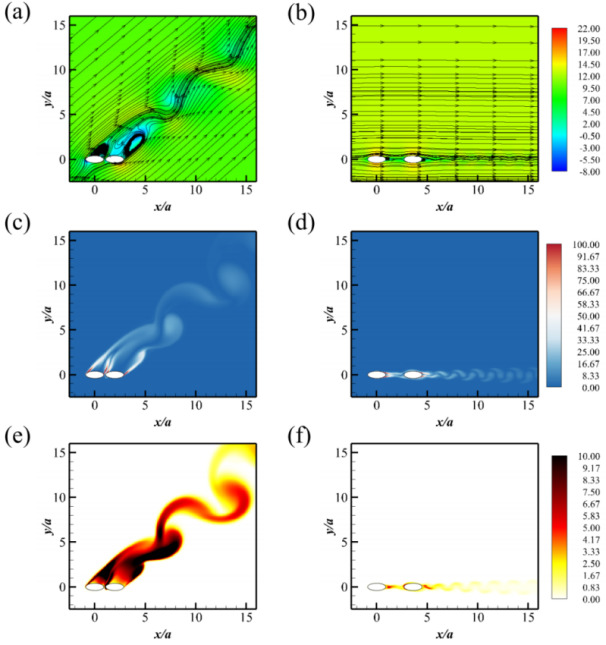
Figure 3. Wake characterizations for the SBB state: (a, b) Contours of x− velocity in the xoz− plane with in-plane streamlines, (c, d) contours of vorticity magnitude, and (e, f) contours of TKE. (a, c, e) represent for the case with S/a=2.2 and θ=45∘ , and (b, d, f) for the case with S/a=4 and θ=0∘ .
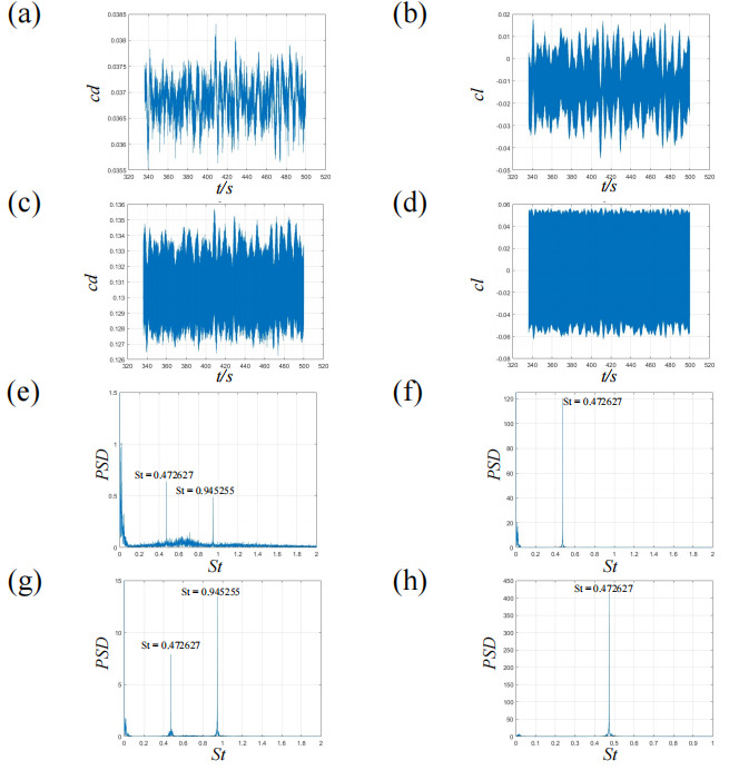
Figure 4. drag coefficients for the SBB state when S/a=2 and θ=0 : (a, c) time histograms of drag coefficient, (b, d) time histograms of lift coefficient, (e, g) FFT of drag coefficients and (f,h) FFT of lift coefficients. (a, b, e, f) represent the leading cylinder, and (c, d, g, h) the trailing cylinder.
3.3 Suppressed vortex shedding
Figure 5 (a) shows velocity contours with superimposed streamlines, with significant periodic variations in the velocity field behind the trailing cylinder, while the flow behind the leading cylinder remains stable. Figure 5 (b) illustrates the vorticity contours for S/a=1.5 , θ=30∘ . Notably, vortex shedding from the leading elliptic cylinder is suppressed by the presence of the trailing cylinder, while vortex shedding from the trailing cylinder persists. This wake regime is classified as the "suppressed vortex shedding" (SVS) state. Figure 5 (c) presents the TKE contours in the wake regime, indicating periodic vortex shedding only from the trailing cylinder, with no shedding observed from the leading one.
The time histories of the drag coefficients for the leading cylinder are shown in Figures 6 (a) and (b). Due to the suppression of vortex shedding, the drag coefficient remains constant. Figures 6 (c) and (d) display the time histories of the drag coefficients for the trailing cylinder, which vary periodically due to vortex shedding. The corresponding frequency spectra of Cd and Cl of the leading and trailing cylinder are provided in Figures 6 (e), (f), (g), and (h), revealing a dominant peak at St=0.362771 .
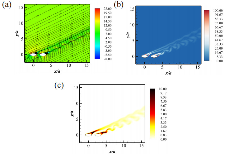
Figure 5. Wake characterizations for the SVS state at S/a=3 and θ=30∘ : (a) Contours of x− velocity in the xoz− plane with in-plane streamlines, (b) contours of vorticity magnitude, and (c) contours of TKE.
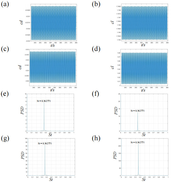
Figure 6. drag coefficients for the SVS state when S/a=1.5 and θ=30∘ : (a, c) time histograms of drag coefficient, (b, d) time histograms of lift coefficient, (e, g) FFT of drag coefficients and (f,h) FFT of lift coefficients. (a, b, e, f) represent the leading cylinder, and (c, d, g, h) the trailing cylinder.
3.4 Coupled vortex shedding
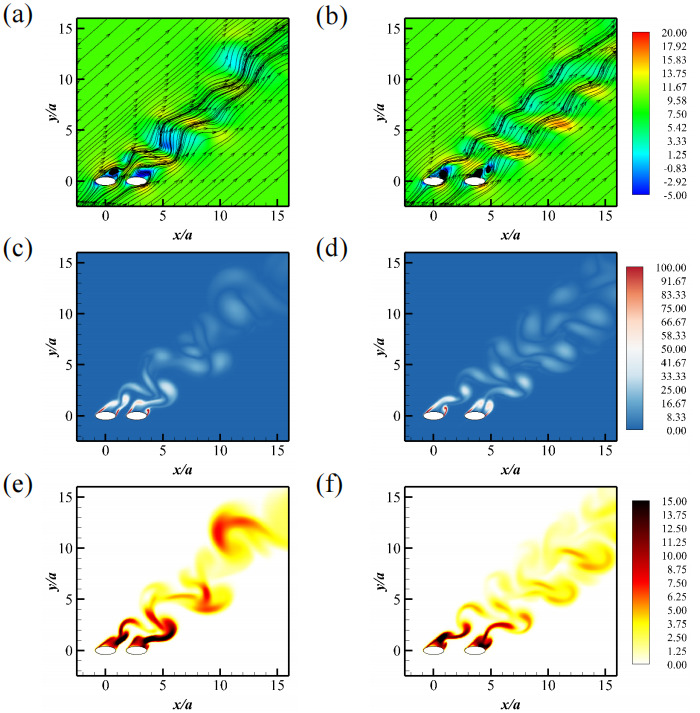
Figure 7. Wake characterizations for the CVS state: (a, b) Contours of x− velocity in the xoz− plane with in-plane streamlines, (c, d) contours of vorticity magnitude, and (e, f) contours of TKE. (a, c, e) represent for the case with S/a=3 and θ=45∘ , and (b, d, f) for the case with S/a=4 and θ=45∘ .
For the cases of S/a=3 , θ=45∘ , and S/a=4 , θ=30∘ and 45∘ , vortex shedding occurs behind both cylinders, resulting in strong downstream interactions between the shed vortex structures, as shown in Figure 7. The wake regime is therefore named "coupled vortex shedding" (CVS).
Figures 7 (a) and (b) present velocity contours with superimposed in-plane streamlines for S/a=3 , θ=45∘ , and S/a=4 , θ=45∘ , respectively. Both velocity fields exhibit periodic patterns characteristic of vortex shedding. Notably, the recirculation zone behind the leading cylinder is significantly larger than that behind the trailing cylinder. Figures 7 (c) through (f) display TKE and vorticity wake patterns that resemble two out-of-phase vortex shedding wakes intersecting and interacting, with distinct areas of convergence and divergence. The resulting wake patterns appear harmonic and homogeneous, without any irregularities.
Time histories of the drag coefficients for the leading and trailing cylinders are displayed in Figures 8 (a, b) and (c, d), respectively. Due to the coupling of vortex shedding between the cylinders, the drag coefficients exhibit periodic behavior consistent with the vortex shedding patterns observed in Figure 8. The frequency spectra shown in Figures 8 (e, g) and (f, h) reveal dominant peaks at identical frequencies, consistent with the periodic behavior mentioned earlier, with a primary peak at St=0.263168 .
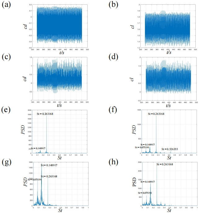
Figure 8. drag coefficients for the CVS state when S/a=1.5 and θ=45∘ : (a, c) time histograms of drag coefficient, (b, d) time histograms of lift coefficient, (e, g) FFT of drag coefficients and (f,h) FFT of lift coefficients. (a, b, e, f) represent the leading cylinder, and (c, d, g, h) the trailing cylinder.
3.5 Anti-phase vortex shedding
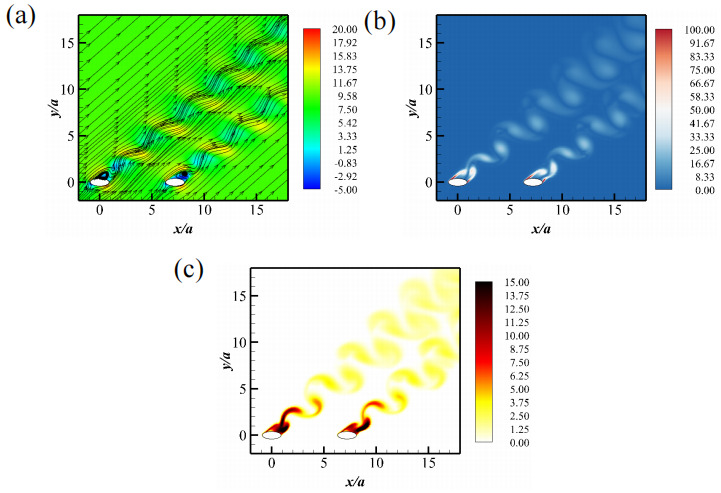
Figure 9. Wake characterizations for the AVS state at S/a=8 and θ=45∘ : (a) Contours of x− velocity in the xoz− plane with in-plane streamlines, (b) contours of vorticity magnitude, and (c) contours of TKE.
As the separation distance increases to S/a=8 and S/a=12 , the wake is characterized by independent vortex shedding from each cylinder, as their interactions become significantly weaker. Figure 9 presents the wake structures characterized by vorticity magnitude contours for the case of S/a=8 , θ=45∘ . As illustrated in Figure 9 (b), independent vortex shedding occurs behind each cylinder. It is noteworthy that the shedding from the leading and trailing cylinders is anti-phased. Correspondingly, the wake regime is named "anti-phase vortex shedding" (AVS).
Figure 9 (a) depicts the velocity contours with superimposed streamlines, showing distinct vortex shedding from both the leading and trailing cylinders, occurring out of phase with each other. Figure 9 (c) displays the TKE contours downstream of the two cylinders, revealing the same periodic shedding pattern for each cylinder, with the TKE gradually dissipating as it moves downstream.
The time histories of the drag coefficients for the leading cylinder are plotted in Figures 10 (a) and (b), while Figures 10 (c) and (d) show the time histories for the trailing cylinder. As expected, the drag coefficients vary periodically over time due to vortex shedding. Both cylinders exhibit equal dominant frequency values, indicating symmetric shedding in the downstream direction. The corresponding frequency spectra of Cd confirm this, with a dominant peak at St=0.213366 .
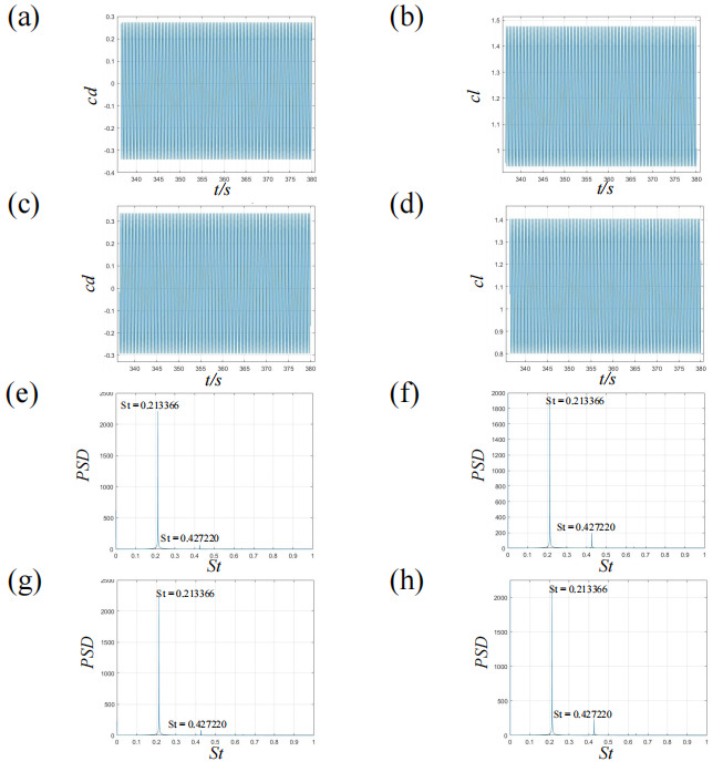
Figure 10. drag coefficients for the AVS state when S/a=4 and θ=45∘ : (a, c) time histograms of drag coefficient, (b, d) time histograms of lift coefficient, (e, g) FFT of drag coefficients and (f,h) FFT of lift coefficients. (a, b, e, f) represent the leading cylinder, and (c, d, g, h) the trailing cylinder.
3.6 In-phase vortex shedding
For the cases of S/a=8 , θ=45∘ , and S/a=12 , θ≥45∘ , the wake interactions between the two cylinders weaken significantly. Independent vortex shedding still occurs behind each cylinder, but the shedding now takes place in-phase. Figures 11 (c) and (d) illustrate the wake structures characterized by vorticity magnitude contours for ( S/a=8 , θ=45∘ ) and ( S/a=12 , θ=45∘ ), respectively. These figures reveal in-phase Kármán vortex shedding in the wake of both cylinders, a regime referred to as "In-phase Vortex Shedding" (IVS).
Figures 11 (a) and (b) show the velocity contours for S/a=8 , θ=45∘ and S/a=12 , θ=45∘ . Synchronized flow separations are evident as the flow passes the elliptic cylinders. Figures 11 (e) and (f) present the TKE wake patterns for S/a=8 , θ=45∘ and S/a=12 , θ=45∘ . These patterns also display in-phase periodic shedding behind the cylinders, with the leading cylinder exhibiting stronger shedding in the upstream region.
The time histories of the drag and lift coefficients for each cylinder are shown in Figures 12 (a, b) and (c, d), respectively. Both drag coefficients fluctuate periodically, consistent with the observed in-phase shedding. The corresponding frequency spectra of the drag and lift coefficients are plotted in Figures 12 (e, g) and (f, h). A dominant peak at St=fau0=0.211901 is observed in all the spectra, confirming the synchronized Kármán vortex shedding behind the two cylinders.
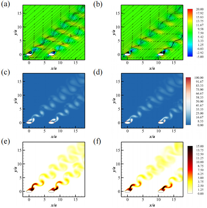
Figure 11. Wake characterizations for the IVS state: (a, b) Contours of x− velocity in the xoz− plane with in-plane streamlines, (c, d) contours of vorticity magnitude, and (e, f) contours of TKE. (a, c, e) represent for the case with S/a=8 and θ=45∘ , and (b, d, f) for the case with S/a=12 and θ=45∘ .
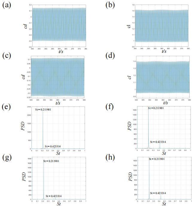
Figure 12. drag coefficients for the IVS state when S/a=6 and θ=45∘ : (a, c) time histograms of drag coefficient, (b, d) time histograms of lift coefficient, (e, g) FFT of drag coefficients and (f,h) FFT of lift coefficients. (a, b, e, f) represent the leading cylinder, and (c, d, g, h) the trailing cylinder.
4 Vortex shedding frequencies
The Strouhal number for the vortex shedding frequencies in the wake of elliptic cylinders in tandem arrangement with respect to the separation distance, at different angles of attack, are shown in figure 13.
For situations producing WOVS, no Strouhal number is derived. When θ=0∘ , the Strouhal number increases with separation. While for θ=30∘ the Strouhal number first increases from S/a=2.2 to S/a=3 and then reduces as the separation increases further. For θ=45∘ , the Strouhal number increases from S/a=3 to S/a=4 , and then decreases as well.
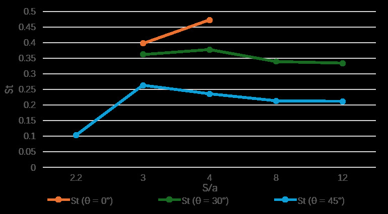
Figure 13. Strouhal number for the vortex shedding frequencies in the wake of elliptic cylinders in tandem arrangement with respect to the separation distance, at different angles of attack
5 Aerodynamic characteristics
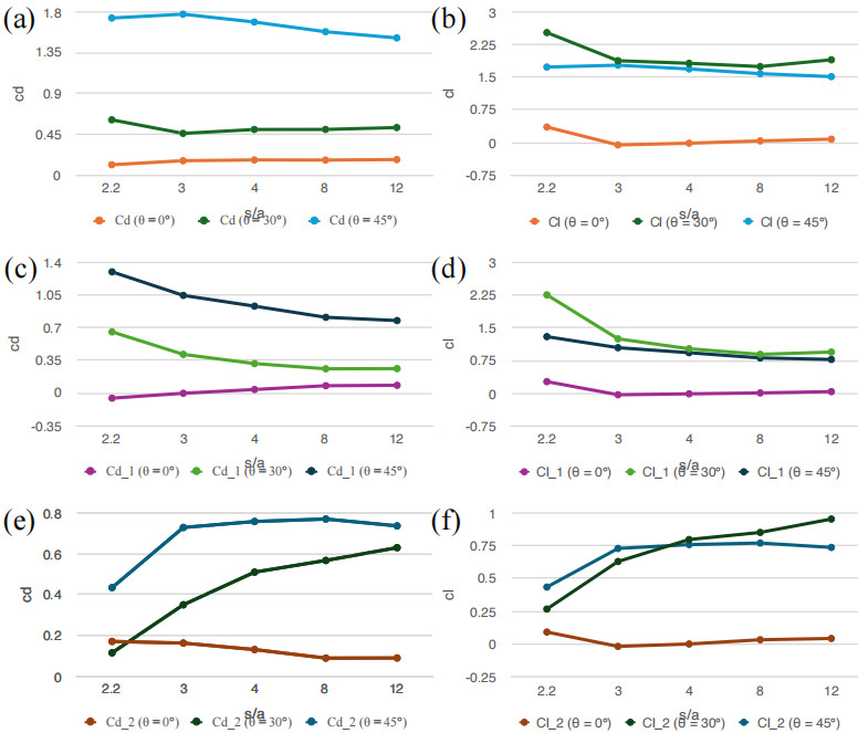
Figure 14. Mean drag and lift coefficients for the elliptic cylinders in tandem with respect to the separation, at different angles of attack: (a, b) total drag/lift cofficients, (c, d) drag/lift coefficients experienced by the leading cylinder, and (e, f) drag/lift coefficients experienced by the trailing cylinder. (a, c, e) represent mean drag coefficients, and (b, d, f) represent mean lift coefficients.
The mean drag and lift coefficients for elliptic cylinders in tandem arrangement, with respect to the separation distance and at different angles of attack, are presented in figure 14. This analysis provides insight into the aerodynamic performance of the cylinders under varying configurations.
Figures 14 (a) and 14 (b) show the total drag ( Cd ) and lift ( Cl ) coefficients for the elliptic cylinders at three angles of attack: 0∘ , 30∘ , and 45∘ , as the separation distance ( S/a ) varies. The drag coefficient Cd slightly decreases with increasing separation distance for all angles of attack, indicating that the drag force experienced by the cylinders reduces as they are spaced further apart. Specifically, at 0∘ and 30∘ angles of attack, the drag coefficient remains relatively stable initially and then shows a slight decrease at larger separation distances. At 45∘ , the drag coefficient starts higher and exhibits a more pronounced decline. Similarly, the lift coefficient Cl trends downward with increasing separation distance for all angles of attack. At 0∘ , the lift coefficient remains nearly constant, while at 30∘ and 45∘ , there is a noticeable decrease. The lift coefficient is highest at 45∘ , reflecting stronger lift forces at this angle of attack, but these forces diminish as the separation distance increases.
Figures 14 (c) and 14 (d) depict the drag ( Cd1 ) and lift ( Cl1 ) coefficients experienced by the leading cylinder. The drag coefficient Cd1 shows a decrease as the separation distance increases, particularly for the 45∘ angle of attack, where the drag force significantly reduces. At 0∘ and 30∘ , the drag coefficients remain relatively stable with slight declines at larger distances. The lift coefficient Cl1 for the leading cylinder follows a similar trend to the total lift coefficient, with values decreasing as the separation distance increases. At 0∘ , the lift coefficient is low and remains stable. At 30∘ and 45∘ , the lift coefficient starts higher and decreases more significantly, indicating that lift forces on the leading cylinder diminish as the separation distance grows. Figures 14 (e) and 14 (f) present the drag ( Cd2 ) and lift ( Cl2 ) coefficients for the trailing cylinder. The drag coefficient Cd2 increases slightly with increasing separation distance at all angles of attack. The most notable increase is observed at 45∘ , where the drag force on the trailing cylinder becomes more pronounced as the cylinders are spaced further apart. The lift coefficient Cl2 for the trailing cylinder shows an increasing trend with separation distance, particularly at 45∘ . At 0∘ and 30∘ , the lift coefficients remain relatively stable with slight increases at larger separation distances.
In summary, at lower separation distances, drag and lift forces are higher due to stronger interactions between the cylinders. As the separation distance increases, these forces generally decrease for the leading cylinder while they increase for the trailing cylinder. The angle of attack also plays a crucial role, with higher angles resulting in stronger initial drag and lift forces that diminish more significantly with increasing separation distance.
6 Flow visualization experiments
Flow visualization experiments were conducted in the Armfield C15-10 wind tunnel at Shanghai Jiao Tong University. A variable-speed fan with maximum velocity of 30m/s , located at the end of the wind tunnel, controlled the airflow, while elliptic cylinders, constructed from 3D printed ABS, were fixed in the test section. These cylinders were designed to match the geometry used in the CFD simulations, scaled down to 1.5cm wide and 5.4cm long. The parameters of the cylinders are determined based on the size of the visible window of the wind tunnel and the area coverage of the laser projector, while also considering the resolution of the incoming airflow. The Laser-Induced Fluorescence (LIF) technique was employed to visualize the flow. This involved introducing a tracer substance into the airflow and illuminating the flow with a laser from below. Water vapor is chosen as the substance in this case for fire-safety and pollution considerations. The diffracted light from the water droplets, captured by high-speed cameras, allowed for the detailed observation of complex flow structures, including vortices and turbulent regions.
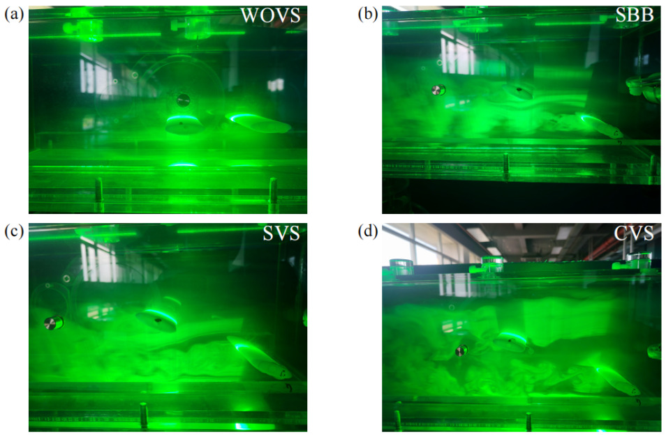
Figure 15. Experimental setup of the Armfield C15-10 wind tunnel at Shanghai Jiao Tong University, showing the Laser-Induced Fluorescence (LIF) system for flow visualization in operation. The green laser beam illuminates the test section, where flow around an elliptic cylinder model is analyzed.
Figure 15 presents a series of flow visualizations illustrating different wake regimes. It captures distinct flow patterns around bluff bodies, revealing the complex interaction between the fluid and the elliptic cylinders. In the WOVS regime, the flow remains relatively stable without vortex formation, while the SBB regime shows clear vortex shedding, and the cylinders act as a single bluff body. The SVS regime demonstrates the suppression of vortex shedding. Finally, the CVS regime displays coupled vortex shedding, where vortices from multiple bodies interact, forming intricate flow structures. These visualized patterns, illuminated by the green fluorescence of the tracer substance, closely correspond with the predictions from CFD simulations, further validating the present numerical simulations.
7 Concluding remarks
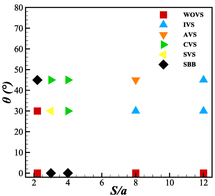
Figure 16. Phase diagram of the wake regimes with respect to separation ratio and angle of attack
This study systematically examines the wake flow patterns using computational fluid dynamics (CFD) simulations based on the RANS equations, validated through physical experiments with 3D-printed models in a wind tunnel. Six distinct wake dynamics were identified: i) Wake states without vortex shedding, ii) Single bluff body wake, iii) Suppressed vortex shedding, iv) Coupled vortex shedding, v) Anti-phase vortex shedding, and vi) In-phase vortex shedding. As summarized in figure 16, Wake states without vortex shedding (WOVS) initially occur at a small separation ratio ( S/a=2.2 ) and at larger separation ratios with zero angle of attack. As the separation ratio and angle of attack increase, the wake transitions to a Single bluff body wake (SBB). When the separation ratio reaches S/a=3−4 and the angle of attack ranges between θ=30∘−45∘ , the wake evolves into Coupled vortex shedding (CVS) and Suppressed vortex shedding (SVS) patterns, as the trailing cylinder moves farther from the recirculation zone. At even larger separations ( S/a=8−12 ), the interaction between the cylinders weakens, leading to the emergence of In-phase vortex shedding (IVS) and Anti-phase vortex shedding (AVS) patterns. Furthermore, the vortex shedding frequencies and aerodynamic characteristics associated with these wake dynamics were carefully examined, providing new insights into their evolution.
This work advances the understanding of wake patterns behind tandem elliptic cylinders at high Reynolds numbers, extending the knowledge base established by previous studies. Future work could further validate these findings across a broader range of Reynolds numbers and aspect ratios, and explore a more detailed topological analysis of the wake patterns formed by the cylinders.
References
[1]. Braza, M., Perrin, R., & Hoarau, Y. (2006). Turbulence properties in the cylinder wake at high Reynolds numbers. Journal of fluids and Structures, 22(6-7), 757-771.
[2]. Rodríguez, I., Lehmkuhl, O., Chiva, J., Borrell, R., & Oliva, A. (2015). On the flow past a circular cylinder from critical to super-critical Reynolds numbers: Wake topology and vortex shedding. International Journal of Heat and Fluid Flow, 55, 91-103.
[3]. Shi, X., Alam, M., & Bai, H. (2020). Wakes of elliptical cylinders at low Reynolds number. International Journal of Heat and Fluid Flow, 82, 108553.
[4]. Sen, S., & Mittal, S. (2017). A study on the far wake of elliptic cylinders. Computer Modeling in Engineering & Sciences, 113(1), 35-55.
[5]. Taneda, S. (1965). Experimental investigation of vortex streets. Journal of the Physical Society of Japan, 20(9), 1714-1721.
[6]. Mizushima, J., & Suehiro, N. (2005). Instability and transition of flow past two tandem circular cylinders. Physics of Fluids, 17(10).
[7]. Duong, V. D., Nguyen, V. D., Nguyen, V. T., & Ngo, I. L. (2022). Low-Reynolds-number wake of three tandem elliptic cylinders. Physics of Fluids, 34(4).
[8]. Hunt, J. C., Wray, A. A., & Moin, P. (1988). Eddies, streams, and convergence zones in turbulent flows. Studying turbulence using numerical simulation databases, 2. Proceedings of the 1988 summer program.
Cite this article
Sui,C. (2024). Turbulent flows past two elliptical cylinders in tandem arrangement: wake dynamics and aerodynamic characteristics. Theoretical and Natural Science,53,262-275.
Data availability
The datasets used and/or analyzed during the current study will be available from the authors upon reasonable request.
Disclaimer/Publisher's Note
The statements, opinions and data contained in all publications are solely those of the individual author(s) and contributor(s) and not of EWA Publishing and/or the editor(s). EWA Publishing and/or the editor(s) disclaim responsibility for any injury to people or property resulting from any ideas, methods, instructions or products referred to in the content.
About volume
Volume title: Proceedings of the 2nd International Conference on Applied Physics and Mathematical Modeling
© 2024 by the author(s). Licensee EWA Publishing, Oxford, UK. This article is an open access article distributed under the terms and
conditions of the Creative Commons Attribution (CC BY) license. Authors who
publish this series agree to the following terms:
1. Authors retain copyright and grant the series right of first publication with the work simultaneously licensed under a Creative Commons
Attribution License that allows others to share the work with an acknowledgment of the work's authorship and initial publication in this
series.
2. Authors are able to enter into separate, additional contractual arrangements for the non-exclusive distribution of the series's published
version of the work (e.g., post it to an institutional repository or publish it in a book), with an acknowledgment of its initial
publication in this series.
3. Authors are permitted and encouraged to post their work online (e.g., in institutional repositories or on their website) prior to and
during the submission process, as it can lead to productive exchanges, as well as earlier and greater citation of published work (See
Open access policy for details).
References
[1]. Braza, M., Perrin, R., & Hoarau, Y. (2006). Turbulence properties in the cylinder wake at high Reynolds numbers. Journal of fluids and Structures, 22(6-7), 757-771.
[2]. Rodríguez, I., Lehmkuhl, O., Chiva, J., Borrell, R., & Oliva, A. (2015). On the flow past a circular cylinder from critical to super-critical Reynolds numbers: Wake topology and vortex shedding. International Journal of Heat and Fluid Flow, 55, 91-103.
[3]. Shi, X., Alam, M., & Bai, H. (2020). Wakes of elliptical cylinders at low Reynolds number. International Journal of Heat and Fluid Flow, 82, 108553.
[4]. Sen, S., & Mittal, S. (2017). A study on the far wake of elliptic cylinders. Computer Modeling in Engineering & Sciences, 113(1), 35-55.
[5]. Taneda, S. (1965). Experimental investigation of vortex streets. Journal of the Physical Society of Japan, 20(9), 1714-1721.
[6]. Mizushima, J., & Suehiro, N. (2005). Instability and transition of flow past two tandem circular cylinders. Physics of Fluids, 17(10).
[7]. Duong, V. D., Nguyen, V. D., Nguyen, V. T., & Ngo, I. L. (2022). Low-Reynolds-number wake of three tandem elliptic cylinders. Physics of Fluids, 34(4).
[8]. Hunt, J. C., Wray, A. A., & Moin, P. (1988). Eddies, streams, and convergence zones in turbulent flows. Studying turbulence using numerical simulation databases, 2. Proceedings of the 1988 summer program.