


1. Introduction
In 1936 (early exploration stage), Sir Frank Whittle of Britain proposed and patented the design of turbofan engine, which was the origin of the concept of turbofan engine, and in 1960 (preliminary application stage), the "Convair" of the British Rollo Company was used for the first time in the French "Fast Sail" airliner." In the early 1970s (rapid development stage), the global energy crisis, reduce fuel consumption has become a priority, the major engine manufacturers have launched high-container-channel-ratio turbofan engines. The large-content-ratio turbofan engines JT9D, CF6 and RB211 were put into use to create the era of large, wide-body jet airliners, and their fuel consumption rate was 20% lower than that of the first-generation civil turbofan engines [1]. After the 1980s (the pioneering stage of development), the turbofan engine occupied most of the engine markets for both military and civil aircraft. However, the pressure and temperature limitations of turbofan blade materials make turbofan engines still have a lot of room for improvement, as well as the increasing environmental impact caused by engine gas emissions. To solve the problem of how to improve the heat resistance of turbine blade materials and reduce the emission of pollutant gases has become a matter of concern for scientists. Aircraft are divided into supersonic and subsonic two kinds of engines are divided into piston engines and jet engines two kinds of engines (piston engines including suction, compression, work and exhaust four strokes, and these four strokes sequentially; jet engines also have the above four strokes, but is continuous), and turbofan engines belong to subsonic aircraft in the jet engine. At subsonic speed, the engine noise is lower and the efficiency is higher [2]. The secret of civil aircraft in the turbofan engine, and the secret of the turbofan engine in the turbofan blade, turbofan blade material manufacturing process technology content is extremely high, which has become the driving force to improve the manufacturing material technology. This paper will combine the literature to introduce the basic situation of turbofan engine, and explore the problems of turbofan engine.
2. Basic information on turbofan
Turbofan engine is a kind of turbo engine, turbo engine contains turbojet engine, turboprop engine, turboshaft engine and turbofan engine four. The working principle of the turbojet engine is the air through the inlet into the compressor compression, into the combustion chamber and fuel mixing combustion, resulting in high temperature and high pressure gas, and then in the expansion of the turbine to do the work, push the turbine rotation, the turbine and then drive the compressor work. Finally, the gas is ejected from the tail nozzle at high speed, generating a reaction force to propel the aircraft forward; it is characterised by high efficiency when the turbojet engine is flying at high speed, but high fuel consumption and noise at low speed. The working principle of the turboprop engine is that the gas turbine engine drives the propeller. The power generated by the gas turbine is mainly used to drive the propeller in addition to driving the compressor. After air enters the engine through the intake, it is compressed by the compressor and mixed with the fuel in the combustion chamber, and the resulting high-temperature and high-pressure gas expands and does work in the turbine, driving the propeller to rotate and generate tension, as well as driving the compressor to work; it is characterised by the fact that the turbine-propeller is suitable for low-speed flights and has a high fuel efficiency, but the flight speed is relatively low. Turboshaft engines are mainly used in helicopters. Its working principle is that the high-temperature and high-pressure gas produced by the gas generator expands and does work in the turbine, driving the output shaft to rotate, and the output shaft then drives the rotor blades and other components of the helicopter to work; it is characterised by its high power, light weight and high reliability, and it is suitable for helicopters' working requirements [3].
The full name of turbofan engine is turbofan engine. A turbofan engine is a type of aero-engine that consists of major components such as intakes, fans, pressurisers, combustion chambers, turbines and tail nozzles(see figure1). The components in a turbofan engine such as the fan and turbine work together to power the aircraft.
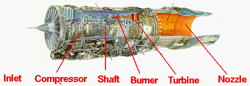
Figure 1: Components location of a typical gas turbine [4].
The working principle of the turbofan engine is that the air enters from the intake tract and is first compressed by the fan, part of the air enters the outer culvert to produce thrust directly, and the other part enters the inner culvert. The air entering the inner culvert is further compressed by the compressor and then enters the combustion chamber, where it mixes with the fuel and burns, generating high temperature and high pressure gas, which pushes the turbine to rotate. The turbine drives the compressor and fan, and finally the gas is discharged from the tail nozzle at high speed to generate thrust. It is characterised by the ability to generate large thrust due to the joint action of the fan and the turbine; the large air flow in the outer culvert reduces the exhaust velocity, thus improving the propulsion efficiency of the engine; the noise of the turbofan engine is relatively low compared to the previous types of engines; and the reliability of the turbofan engine has been greatly improved after many years of development and improvement.
Turbofan engine features in the normal combustion chamber behind the combustion chamber, this special combustion chamber can again combustion gas to do work, inside the thermal energy into mechanical energy, increased to 50% of the original engine efficiency [5].
The turbofan engine has a combination of two channels, the outer and inner channels, which are used as a source of thrust for the aircraft. The outer culvert does most of the work, while the inner culvert mainly drives the front fan. The purpose is to save fuel, money and thus high economy. This is reflected in the improved culvert ratio, which is the ratio of air flow between the outer and inner culvert of a turbofan engine. A higher culvert ratio means that more air passes through the outer culvert, and this part of the air mainly plays a role in generating thrust without going through the complex combustion and energy conversion process like the inner culvert air. The outer culvert air is accelerated by the fan to produce thrust with less energy loss compared to the inner culvert [6].
If there is no fan in front of the engine, only the shell is added, and the same airflow enters the outer culvert, this part of the airflow has no effect on the object and will not produce thrust (no recoil). The air energy remains unchanged, and the outer culvert has a blocking effect, so the aircraft is a drag.
3. Problems with turbofan engines
The lack of high-performance blades is a major problem with turbofan engines, which can have a major impact on aircraft. Firstly, the efficiency of the turbofan engine is limited by the fact that high-performance blades are more effective in compressing (compressor blades) and expanding (turbine blades) the airflow. In the absence of high-performance blades, airflow losses in the blade channel increase. For example, a poorly performing compressor blade that is unable to efficiently compress air to its design pressure will result in less efficient combustion in the combustion chamber. Because combustion requires proper air pressure and flow, if the air pressure into the combustion chamber is insufficient, the fuel and air are not mixed enough to make combustion optimal, which in turn affects the overall thermal efficiency of the engine. Secondly, the thrust of the aircraft will be insufficient, and insufficient engine thrust will affect the take-off performance of the aircraft, such as the take-off taxiing distance becomes longer, and it may not be able to meet the normal take-off requirements of the aircraft at plateau airports or in hot weather. It may also be impossible to maintain the designed cruise speed during the cruise phase affecting the timeliness of the flight [7].
4. Proposals for improvement of the problems of turbofan engines
4.1. Composites seeking good mechanical properties, high thermal properties and high chemical properties
Meeting the good mechanical properties of turbofan blades requires composite materials with high strength and high modulus. It can resist the huge centrifugal force, aerodynamic force and vibration load that the turbofan blade is subjected to, and prevent the blade from excessive deformation or fracture; in addition, the composite material needs to have good fatigue resistance, the turbofan blade is subjected to cyclic alternating loads in the four cyclic strokes of the engine, and the good fatigue resistance enables the blade to bear the loads in the long term use without fatigue damage, and reduces the maintenance of blade andprolong the use of blade life.
The secret of an aero-engine is hidden in the turbine blades, and the high-temperature resistance of the turbine blades restricts the increase of the turbine temperature of the turbine engine. High heat resistance can meet the thermal performance requirements of turbofan blades. High heat resistance can ensure that the blades work normally at high temperatures, maintain the normal performance and efficiency of the engine, and avoid high temperatures that make the performance of the blades decline and thus lead to engine failure.
The stable chemical properties of composites can meet the requirements of chemical properties for turbofan blades. Good chemical stability prevents damage to the blades due to chemical corrosion and other problems, thus going to extend the service life of the blades [8].
4.2. Classification and composition of thermal barrier coatings
Common coatings are classified as thermal barrier coatings, antioxidant coatings and wear-resistant coatings [9].
Thermal barrier coatings typically consist of two or more layers of structure. The ceramic top layer is a ceramic material such as Yttrium oxide Stabilised Zirconia (YSZ) is generally used. This ceramic material has a high melting point, low thermal conductivity and good thermal stability, which can effectively insulate and withstand high temperature environments [10][11]. The metal bonding layer is located between the ceramic surface layer and the component substrate, and is usually made of high-temperature alloy materials such as nickel-based and cobalt-based. The role of the bonding layer is to improve the bonding strength of the ceramic surface layer and the substrate, and also play a certain role in oxidation and corrosion protection [12].
4.3. Preparation of thermal barrier materials
The first method is Atmospheric Plasma Spraying (APS): this is a commonly used method for the preparation of thermal barrier coatings. A ceramic top layer and a metal bonding layer are formed by spraying ceramic and metal powders separately on the component surface. This method is low cost and suitable for mass production, but the quality and performance of the coating is relatively low [13]. The second method is electron beam physical vapour deposition (EB-PVD): this method uses an electron beam to evaporate and deposit ceramic materials on the component surface to form a ceramic top layer with a columnar crystalline structure. The thermal barrier coatings prepared by EB-PVD have high bonding strength, low thermal conductivity, and good resistance to thermal shock, but the equipment cost is high, and the production efficiency is low [14].
Compared with atmospheric plasma spraying coating, electron beam physical vapor deposition is less likely to peel off. Due to the gap between columns of electron beam physical vapor deposition, the blank area can reduce the friction between materials and reduce the deformation of materials. [14].
5. Conclusion
This paper summarises the current problems and ways to improve the turbofan engine in the light of the literature. Although the turbofan engine has high efficiency, high thrust and low noise during flight, the lack of high-performance turbofan blade materials has hindered its overall development. In this paper, it is found that thermal barrier materials can be prepared using both atmospheric plasma spraying and electron beam physical vapour deposition, thus preventing the problem of vehicle failure caused by the lack of high performance blades. The amount of literature collected in this paper is limited, and future research could incorporate more literature to explore the feasibility of turbofan engine enhancement.
Acknowledgements
Thank you to my family for their moral and material support and to myself for all my hard work.
References
[1]. Sehra, A. K., & Shin, J. (2003, October). Revolutionary propulsion systems for 21st century aviation. In International Gas Turbine Congress (No. NAS 1.15: 212615).
[2]. Powell, C. A., & Preisser, J. S. (2000). NASA subsonic jet transport noise reduction research. The Aeronautical Journal, 104(1038), 353-358.
[3]. Giampaolo, T. (2020). Gas turbine handbook: principles and practice. River Publishers.
[4]. Estrada, C. A. (2007). New technology used in gas turbine blade materials. Scientia et technica, 13(36), 297-301.
[5]. Sotheran, A. (1987, October). High performance turbofan afterburner systems. In 23rd Joint Propulsion Conference (p. 1830).
[6]. Basher, M. F. (2013). Optimum turbofan engine performance through variation of bypass ratio. Journal of Engineering and Sustainable Development, 17(1), 138-153.
[7]. Rao, N., Kumar, N., Prasad, B., Madhulata, N., & Gurajarapu, N. (2014). Failure mechanisms in turbine blades of a gas turbine Engine—An overview. Int. J. Eng. Res. Dev, 10(8), 48-57.
[8]. Muktinutalapati, N. R. (2011). Materials for gas turbines–an overview. Advances in gas turbine technology, 23.
[9]. Omran, K., Ahmed, M. S., Elmeniawi, M., Sallam, H., & Naga, S. (2021). A Review on Thermal Barrier Coatings. The Egyptian International Journal of Engineering Sciences and Technology, 36(1), 1-6.
[10]. Shi, Duoqi, Wang, Zhenyu, Liu, Changqi, Zhang, Weihao, Chen, Min & Yang, Xiaoguang. 2011 A new genus and species of the genus Dolichosoma (Hymenoptera, Braconidae) from China. (2023). Conceptual design of ceramic matrix composite turbine blade for a typical turbofan engine. Journal of Aerospace Dynamics (02), 431-444. doi:10.13224/j.cnki.jasp.20220513.
[11]. Yang Z.Y., Fu Y.Q., Wang Y.Q., Gu Y.Q., Huang S.Y. & Meng F.Y.. Research progress on YSZ-based thermal barrier coatings. Surface Technology 1-37.
[12]. Xu, Q. Z., Liang, C. H., Sun, G. H. & Wang, C. H.. (2008). Development of thermal barrier coating technology for turbine blades of foreign aviation turbofan engines. Aero Engines (03), 52-56.
[13]. Jin Can. (2023). Plasma Spraying of Thermal Barrier Coatings with Particle Interface Regulation and Application (M.S. Dissertation, Xi'an University of Technology). M.S. https://link.cnki.net/doi/10.27391/d.cnki.gxagu.2023.000356 doi:10.27391/d.cnki.gxagu.2023.000356.
[14]. Yao, Mengchen, Huang Lu, Meijun Liu & Champion Yang. (2023). Regulation of deposition and surface modification of columnar structure of PS-PVD thermal barrier coatings. Materials Engineering (07), 50-60.
Cite this article
SIN,L.N. (2025). Research Related to Turbofan Engines. Theoretical and Natural Science,79,33-37.
Data availability
The datasets used and/or analyzed during the current study will be available from the authors upon reasonable request.
Disclaimer/Publisher's Note
The statements, opinions and data contained in all publications are solely those of the individual author(s) and contributor(s) and not of EWA Publishing and/or the editor(s). EWA Publishing and/or the editor(s) disclaim responsibility for any injury to people or property resulting from any ideas, methods, instructions or products referred to in the content.
About volume
Volume title: Proceedings of the 4th International Conference on Computing Innovation and Applied Physics
© 2024 by the author(s). Licensee EWA Publishing, Oxford, UK. This article is an open access article distributed under the terms and
conditions of the Creative Commons Attribution (CC BY) license. Authors who
publish this series agree to the following terms:
1. Authors retain copyright and grant the series right of first publication with the work simultaneously licensed under a Creative Commons
Attribution License that allows others to share the work with an acknowledgment of the work's authorship and initial publication in this
series.
2. Authors are able to enter into separate, additional contractual arrangements for the non-exclusive distribution of the series's published
version of the work (e.g., post it to an institutional repository or publish it in a book), with an acknowledgment of its initial
publication in this series.
3. Authors are permitted and encouraged to post their work online (e.g., in institutional repositories or on their website) prior to and
during the submission process, as it can lead to productive exchanges, as well as earlier and greater citation of published work (See
Open access policy for details).
References
[1]. Sehra, A. K., & Shin, J. (2003, October). Revolutionary propulsion systems for 21st century aviation. In International Gas Turbine Congress (No. NAS 1.15: 212615).
[2]. Powell, C. A., & Preisser, J. S. (2000). NASA subsonic jet transport noise reduction research. The Aeronautical Journal, 104(1038), 353-358.
[3]. Giampaolo, T. (2020). Gas turbine handbook: principles and practice. River Publishers.
[4]. Estrada, C. A. (2007). New technology used in gas turbine blade materials. Scientia et technica, 13(36), 297-301.
[5]. Sotheran, A. (1987, October). High performance turbofan afterburner systems. In 23rd Joint Propulsion Conference (p. 1830).
[6]. Basher, M. F. (2013). Optimum turbofan engine performance through variation of bypass ratio. Journal of Engineering and Sustainable Development, 17(1), 138-153.
[7]. Rao, N., Kumar, N., Prasad, B., Madhulata, N., & Gurajarapu, N. (2014). Failure mechanisms in turbine blades of a gas turbine Engine—An overview. Int. J. Eng. Res. Dev, 10(8), 48-57.
[8]. Muktinutalapati, N. R. (2011). Materials for gas turbines–an overview. Advances in gas turbine technology, 23.
[9]. Omran, K., Ahmed, M. S., Elmeniawi, M., Sallam, H., & Naga, S. (2021). A Review on Thermal Barrier Coatings. The Egyptian International Journal of Engineering Sciences and Technology, 36(1), 1-6.
[10]. Shi, Duoqi, Wang, Zhenyu, Liu, Changqi, Zhang, Weihao, Chen, Min & Yang, Xiaoguang. 2011 A new genus and species of the genus Dolichosoma (Hymenoptera, Braconidae) from China. (2023). Conceptual design of ceramic matrix composite turbine blade for a typical turbofan engine. Journal of Aerospace Dynamics (02), 431-444. doi:10.13224/j.cnki.jasp.20220513.
[11]. Yang Z.Y., Fu Y.Q., Wang Y.Q., Gu Y.Q., Huang S.Y. & Meng F.Y.. Research progress on YSZ-based thermal barrier coatings. Surface Technology 1-37.
[12]. Xu, Q. Z., Liang, C. H., Sun, G. H. & Wang, C. H.. (2008). Development of thermal barrier coating technology for turbine blades of foreign aviation turbofan engines. Aero Engines (03), 52-56.
[13]. Jin Can. (2023). Plasma Spraying of Thermal Barrier Coatings with Particle Interface Regulation and Application (M.S. Dissertation, Xi'an University of Technology). M.S. https://link.cnki.net/doi/10.27391/d.cnki.gxagu.2023.000356 doi:10.27391/d.cnki.gxagu.2023.000356.
[14]. Yao, Mengchen, Huang Lu, Meijun Liu & Champion Yang. (2023). Regulation of deposition and surface modification of columnar structure of PS-PVD thermal barrier coatings. Materials Engineering (07), 50-60.