


1. Introduction
With the rapid development of modern technology, electronic devices are widely used in various fields, but the problem of electromagnetic interference (EMI) is becoming increasingly serious. EMI may lead to data errors, degradation of equipment performance, system failure or equipment damage [1]. With so many electronic devices operating in close proximity, it is critical to ensure that each device operates properly in an electromagnetic environment without causing intolerable interference to other devices. The aim of the article is to provide a comprehensive analysis of EMC and EMI, which will help the reader to understand the main elements of EMC and EMI initially.
The article first describes the basic concepts of EMC and EMI. EMI can be in the form of conducted or radiated interference, and it poses significant threats to the normal operation of electronic devices. EMC, on the other hand, requires devices to operate within the limits of the electromagnetic environment and be immune to a certain degree of interference. It also reviews the specific evolution of the means of response to EMI in the course of history, from simple shielding methods to more advanced techniques. The article goes on to discuss the application of EMC and EMI in wireless communications, such as constructing efficient models to solve RF desensitization problems, dealing with EMI challenges in OAM mode communications, and performing EMC analysis to aid spectrum management in 5G technology. In the field of new energy vehicles, the article emphasizes that the large number of electronic components makes them highly demanding in terms of EMC and interference immunity. Traditional methods such as filtering, shielding and PCB layout optimization can solve some of the EMI problems. Finally, the article discusses current EMC and EMI challenges, such as spectrum straining and EMI issues in wireless systems, and presents the latest research results, including new modulation techniques and signal processing methods to meet complex EMC specifications.
2. Basic concepts of EMC and EMI
2.1. Discovery and fundamentals of EMI
EMI is a phenomenon in an electronic device or system, which causes performance degradation or function failure because of electromagnetic fields. EMI can be generated by various sources, like power lines, radio transmissions, electrical equipment operation, and even natural phenomena such as lightning. EMI may lead to data errors, equipment performance degradation, system failure or equipment damage [1]. EMI is an electromagnetic phenomenon long - recognized. In 1881, the British scientist Heaviside published the article “On Interference”, marking the start of interference study.
EMI is mainly a process where external electromagnetic fields change, propagate through conductive media or space, then couple with working electronic equipment, thus affecting its normal work. The article further describes this process specifically. EMI is categorized into two forms: conducted and radiated [2]. After an interference signal is generated in a circuit, it propagates along the wires connecting the circuits. The other is radiated conduction, which mainly comes from electromagnetic waves. When a charge is accelerated, a changing electric field is produced. According to Faraday's law of electromagnetic induction, this changing electric field induces a rotating magnetic field.
\( ∇×E=-\frac{∂B}{∂t} \) (1)
where E means electric field strength, B means magnetic induction, t means time. Similarly, according to Ampere's law with Maxwell's correction term, a varying magnetic field induces a rotating electric field.
\( ∇×H=J+{ε_{0}}\frac{∂E}{∂t} \) (2)
where H means magnetic field intensity, J means displacement current density. When a varying electric field produces a varying magnetic field, and that varying magnetic field produces a varying electric field, the two fields excite each other, creating a self-sustaining wave-like propagation pattern. This pattern is an electromagnetic wave. When radiated interference reaches an electronic device, it induces voltages and currents on conductors within the device. According to Faraday's Law of Electromagnetic Induction, a varying magnetic field produces an induced electromotive force in a closed loop, which generates a current. An electric field acting on a conductor redistributes the charge on the conductor, creating a voltage difference. These induced voltages and currents may be superimposed on the original normal signals within the equipment, interfering with the normal operation of the equipment. For example, external EMI may cause the signal from an audio amplifier to become noisy, affecting the sound quality.
2.2. Concept of EMC
Electromagnetic compatibility (EMC) is the ability of a device or system to operate in compliance with the requirements of its electromagnetic environment and not cause intolerable electromagnetic interference to any equipment in its environment. EMC includes two requirements: on the one hand, it refers to the normal operation of the equipment in the process of the environment cannot exceed a certain limit of electromagnetic interference; on the other hand, it is referred to as the apparatus of the environment where the existence of electromagnetic interference has a certain degree of immunity, i.e. electromagnetic sensitivity. A certain degree of immunity, that is, electromagnetic sensitivity.
2.3. Historical Development of EMC
With the emerging use of electric light in the mid-19th century, the development of long-range wireless telegraphy in the late 19th century, and its adoption by the U.S. military soon afterward, led to the need for EMC testing. In the early days of wireless telegraphy, the U.S. Navy reported an inability to receive intelligible information when multiple transmitters were used simultaneously. This was because the transmitters were all tuned to the same operating frequency, a problem that was relatively easy to solve. However, the problem demonstrated to observers the need to monitor these new technologies being developed and how they interacted with each other, especially as the general public began to integrate electronic devices into their daily lives. As a result, laws were adopted by various Western governments in the late 19th century, and the International Electrotechnical Commission (IEC) was formed in 1906, quickly becoming the leading advocate for EMC testing and standardization.
In response to electromagnetic interference, simple means of shielding began to be used. For some sensitive equipment, such as early telegraph communication equipment, the use of metal shells for wrapping. This metal shell can play a certain role in electromagnetic shielding, the principle is to use the metal on the electromagnetic signal reflection and absorption, to prevent external electromagnetic interference into the internal equipment [3]. However, different electronic devices work in different frequency bands, a single shielding material is difficult to meet the requirements of effective shielding of electromagnetic interference in a wide frequency band, prompting technicians to explore multi-layer shielding structure. Such as the combination of inner layer of copper foil outer layer of aluminum shell to cope with a variety of frequencies of electromagnetic interference.
Around the 1980s, almost at the same time as the initial application of multi-layer shielding structure, for the low-frequency magnetic field shielding effect is not good, based on the low-frequency magnetic field characteristics and magnetic materials electromagnetic properties of in-depth study, began the shielding material in the addition of magnetic materials to explore. Magnetic materials, such as ferrite and amorphous alloys, have a high permeability that provides a low impedance path for electromagnetic interference signals as they pass through, thereby directing these signals into the magnetic material. The decrease in permeability of the magnetic material results in a decrease in the inductive component of the inductor, but at the same time the losses in the core increase and the resistive component increases, resulting in an increase in the total impedance. In this way, as the signal passes through the magnetic material, the electromagnetic interference is absorbed and converted into dissipated energy in the form of heat.
In the 1980's - 1990's, as the power purity requirements of electronic equipment increased, significant efforts were made to develop high-performance filters on power lines. Filters are designed with the impedance characteristics of the circuit in mind, and by matching the impedance of the input and output ports to reduce reflected signals and ensure that signals can be transmitted efficiently. Starting in the 1990s, with the gradual maturation of Surface Mount Technology (SMT), the miniaturization of filtering components had a technological basis. The use of miniaturized inductive and capacitive components to build filters began to be experimented with in small electronic devices such as cell phones, the predecessor of cellular phones [4].
In the 1980s, with the PCB electromagnetic radiation mechanism of in-depth study, began to recognize the importance of reasonable division of power and ground layers. In some simple digital circuit PCB designs, attempts were made to set the power and ground layers next to each other to reduce electromagnetic radiation. In the 1980s - 1990s, attempts were made to use different layout strategies in multilayer PCB designs.
In the early 21st century, with the development of computer technology and electromagnetic simulation algorithms, electromagnetic compatibility analysis software began to be applied to PCB design. In the design stage, it is possible to predict and optimize the EMC of PCB more accurately [5]. At the same time, EMC is also moving towards standardization, the International Special Committee on Radio Interference (CISPR) and the U.S. Federal Communications Commission (FCC) and other organizations to develop standard test methods. For the test of radiated interference, the requirements of the test site, the type of antenna and the placement position are determined. Historical Development of EMC is shown in Figure 1.
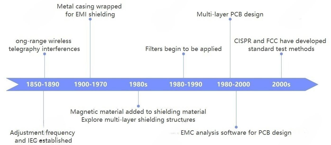
Figure 1: Historical Development of EMC
3. Specific applications of EMC and EMI
3.1. EMC/EMI management in wireless communications
EMC has a wide range of applications in dealing with EMI in our daily lives. Among them wireless communication is what we experience every day. Modern wireless communication equipment usually integrates a large number of digital circuits, and these circuits generate different levels of electromagnetic noise during operation. If these noises are not effectively controlled, they can easily interfere with the wireless receiver in the same device and reduce its sensitivity. How to avoid these noises is extremely important.
One of the first steps to solve this problem is a complete EMI measurement setup for better optimization. In modern highly integrated electronics, ICs have complex structures and involve intellectual property protection, and traditional models that include all geometries and dedicated sources are computationally overloaded and require knowledge of the IC supplier's intellectual property information, which is not feasible in practice. After reading some related papers, Chulsoon Hwang's paper presents an efficient model that provides an intuitive and effective tool for analyzing RF desensitization. In the paper, a dipole moment-based noise source model is constructed, which does not rely on the proprietary information of the IC. In this study, the equivalent dipole moment method is used to represent any current carrying wire as a Hertzian dipole, and the IC can be replaced by a set of magnetic and/or electric dipole moments located in the XY plane, which radiate the same electromagnetic field as the original source. The dipole moment sources are reconstructed by near-field scanning. The electric and magnetic dipoles are first assumed to be tiny linear wires (satisfying certain conditions), and a two-step procedure is followed to determine the magnetic and electric vector potentials and hence the electromagnetic field [6]. The estimation errors of the primary and secondary antennas in the RF desensitization model validation experiments in cell phones are mostly within 5 dB.
Meanwhile, with the development of wireless communication technology and the increasing demand for higher data rates, OAM modes have received much attention as a potential method to increase data rates. OAM modes are different from common plane waves with spiral field distribution. They can be used as multiple independent communication channels, thus promising to increase the data rate in wireless communications [7]. In some environments, OAM modes are orthogonal in wireless communications, meaning that they can be excited and received independently. However, OAM modes have considerable challenges when it comes to EMI, and this is where the application of EMC becomes particularly important. For example, in OAM mode wireless communication, crosstalk mainly originates from acyclic symmetry [8]. When the corridor or array elements of a non-ideal structure are changed from radial to horizontal alignment, the orthogonality between the modes is destroyed, resulting in crosstalk. To solve the crosstalk problem, the effect of symmetry can be reduced by adjusting the geometry and orientation of the antenna array. In communication environments with reflective surfaces, such as above conductive ground, reflections from OAM patterns occur, and to mitigate the effects of reflections, the method of focusing the OAM patterns can be adopted to make the signal transmission more concentrated and reduce the possibility of reflections [8]. By studying and applying these aspects, the impact of EMC issues on OAM mode wireless communications can be effectively managed and mitigated, and the performance and reliability of the system can be improved to better utilize the potential of OAM mode to enhance data rates in wireless communications.
As the latest 5G technology, new solutions are needed to face EMI. 5G has huge advantages over the past, such as high speed and low latency. However, the fundamental characteristics of 5G millimeter wave technology determine its limited penetration, and there are higher requirements in base station deployment to achieve the best results. Under the common 6700 - 7075 MHz band interference, EMC analysis can be used to derive the short and long term interference separation distances required to achieve compatibility between 5G networks and FSS earth stations in cross-border scenarios. Monte Carlo analysis simulations are used to estimate the interference level of the 5G network to the FSS earth station using the Interference - Noise (I/N) protection criterion. We can conclude that the separation distances required to achieve compatibility between 5G networks and FSS earth stations in cross-border scenarios are 26 - 20 km for short-term interference and 23 - 19 km for long-term interference, which is important for spectrum management and future 5G deployment planning [9].
3.2. EMC/EMI and its Safety in New Energy Vehicles
Electric vehicles are also a rapidly developing field in the past few years. Electric vehicles have the advantage of being clean and environmentally friendly, effectively reducing carbon emissions. However, compared with the internal combustion engine structure of traditional automobiles, electric vehicles use a large number of electronic components and high energy density battery systems, which makes electric vehicles have higher safety requirements and anti-interference capabilities in the variable electromagnetic environment.
According to the introduction above, we know that one of the main moments to generate EMI is when the circuit is turned on and off. And the ignition system of the electric vehicle engine will generate strong electromagnetic pulse, if the power system does not have good EMC performance, it may interfere with the normal operation of the on-board electronic equipment. Which filtering, shielding and PCB layout optimization and other traditional methods in circuit design are still the main methods to solve the EMI problems of electric vehicles. For example, in the design of obtaining 24V DC power from a three-phase 415V AC power line, adding a common-mode filtering circuit in the circuit of the input stage can effectively suppress common-mode EMI, preventing external common-mode interference from entering the internal circuitry of the power supply, and also reducing the impact of common-mode noise generated by the internal circuitry on the outside world. In some of the higher EMI suppression requirements of the power supply design, you can also use two or more levels of filtering structure. This can achieve excellent noise suppression over a wide frequency range. Reasonable component layout can also reduce the generation and propagation of electromagnetic interference. For example, in power supply designs using buck converter integrated circuits (ICs), bypass pin capacitors are placed as close as possible to the source and bypass pins, and LinkSwitch - TN2 components are laid out away from the AC input line to improve the EMC performance of the entire power supply circuit [10].
Another key component of an electric vehicle is the drive motor. The electric drive system is new and consists of a high-voltage power supply, an inverter, a motor, and shielded or unshielded high-power cables. If it is treated as a conventional automotive component and subjected to EMI test procedures and conventional emission limitation requirements, serious incompatibility problems can arise. Based on previous studies, it has been found that in electric drive systems, power electronics systems (such as insulated gate bipolar transistors IGBTs in power converters) are the main source of EMI generation. The use of simplified equivalent circuits to predict EMI in high power density inverters has proven to be effective. The high-frequency representation of motors, which has been studied for other applications over the years, can be applied to EMI prediction for electric vehicles [11]. This series of results lays a solid theoretical foundation for the research, development and testing of electric vehicles, and helps to promote the continuous optimization of electric vehicles in terms of EMC and other aspects, thus enhancing the overall performance and safety of electric vehicles.
4. EMC/EMI Challenge and Recent studies
Spectral strain is one of the major problems facing electromagnetic compatibility nowadays. Spectral line tension refers to the overlapping or close proximity of the operating frequencies of multiple electronic devices or systems within a limited frequency resource, which may lead to the exacerbation of electromagnetic interference problems. When multiple devices share similar frequencies, the interference signals they generate may be superimposed on each other, resulting in signals that would not otherwise cause interference when each is used individually to cause interference at the shared frequency, thus affecting the normal operation and performance of the equipment, especially when the frequency of the interference signal is very close to the operating frequency of the equipment, the immunity of the equipment may be reduced, thus increasing the risk of interference to the equipment The risk of interference with the device is increased.
Facing these problems, in Sergey Loyka's paper, a transient quadrature technique is proposed for analyzing EMI problems in wireless systems and networks [12]. The authors point out that currently mutual interference between wireless systems is considered in a simplified way mainly at the frequency planning stage, where instead of using a comprehensive transmit and receive model, only some basic parameters are considered. This approach does not guarantee that EMI can be avoided in any scenario. This thesis finds a computationally efficient behavioral-level numerical simulation approach at the theoretical level, aiming to combine orthogonal modeling techniques and discrete techniques to construct a simulation technique capable of modeling the behavior of circuits or systems over a wide range of frequencies and dynamics, taking into account the AM - AM (envelope magnitude - amplitude) and AM - PM (envelope amplitude - phase) conversions [12].
At the same time, due to the limitations of the complete EMC specification, constraining and processing the spectral lines to meet the EMC specification is also a low-cost solution. A recent research paper points out the limitations of pulse-shaping orthogonal frequency division multiplexing (PS - OFDM) currently used in meeting complex EMC specifications, which can significantly limit the signal amplitude, require the closure of more sub-channels and affect the system capacity. Instead, the new paper introduces a Pulse Shaping Circular Block Filtered Multitone Modulation (PS - CB - FMT), which is first obtained by replacing linear convolution with circular convolution to obtain Circular Block Filtered Multitone Modulation (CB - FMT) from a general multicarrier modulated signal expression [13]. Pulse shaping is performed on top of the CB - FMT to obtain the PS - CB - FMT. At the receiving end of the PS - CB - FMT, the cyclic prefix (CP) is first removed, and then, for each subchannel, a cyclic convolution is performed between each block of received coefficients and an analyzed prototype pulse matched to the synthesized pulse. This cyclic analysis filter bank can be implemented in the frequency domain using a series of Discrete Fourier Transforms (DFTs) and the minimum mean square error equalization is achieved directly in the frequency domain for each sub-channel [13]. It is able to better meet the specification requirements, thus increasing the system capacity and solving the problem of increasing the PLC system capacity while meeting the EMC specifications.
5. Conclusion
This article comprehensively analyses the basic concepts, historical development, specific applications and current challenges of Electromagnetic Compatibility (EMC) and Electromagnetic Interference (EMI). The development of EMC has gone through a process from simple shielding to complex technologies, including the application of multilayer shielding structures and high-performance filters. In the field of wireless communication, the new OAM mode and spectrum management in 5G technology put forward higher requirements for EMC. In the field of new energy vehicles, due to the use of a large number of electronic components, traditional EMI solutions have been emphasized and integrated for application. With the continuous advancement of technology, the EMC field is facing challenges such as spectrum tension and mutual interference between wireless systems. This article integrates and summarizes new modulation techniques and signal processing methods proposed in recent research to meet complex EMC specifications.
Looking ahead, EMC research needs to continue to adapt to technological developments. As the number of electronic devices increases and their functionality becomes more complex, EMC design must become more intelligent and automated to cope with the growing EMI problem. In addition, more interdisciplinary research is needed to address these challenges, which requires experts from a variety of disciplines, including electrical engineering, materials science, and computer science, to work together. At the same time, as global awareness of EMC issues increases, we can expect to see more international co-operation and the development of harmonized standards to promote technical compatibility and safety in the global market. Through these efforts, we can ensure the reliability and performance of electronic equipment in complex electromagnetic environments while protecting against the potential risks of electromagnetic interference.
References
[1]. Mariappan P M, Raghavan D R, Aleem S H E A, et al. Effects of electromagnetic interference on the functional usage of medical equipment by 2G/3G/4G cellular phones: A review. Journal of Advanced Research, 2016, 7(5): 727-738.
[2]. Natarajan S, Babu T S, Balasubramanian K, et al. A state-of-the-art review on conducted electromagnetic interference in non-isolated DC to DC converters. IEEE Access, 2019, 8: 2564-2577.
[3]. Paul C R, Scully R C, Steffka M A. Introduction to electromagnetic compatibility. John Wiley & Sons, 2022.
[4]. Ramdani M, Sicard E, Boyer A, et al. The electromagnetic compatibility of integrated circuits—Past, present, and future. IEEE Transactions on Electromagnetic Compatibility, 2009, 51(1): 78-100.
[5]. Ott H W. Electromagnetic compatibility engineering. John Wiley & Sons, 2011.
[6]. Hwang C. RF desensitization in wireless devices. RF Systems, Circuits and Components. IntechOpen, 2018.
[7]. Ebrahim A, Celik A, Alsusa E, et al. NOMA/OMA mode selection and resource allocation for beyond 5G networks. 2020 IEEE 31st Annual International Symposium on Personal, Indoor and Mobile Radio Communications. IEEE, 2020: 1-6.
[8]. Wulff M, Wang L, Schuster C. The EMC of Orbital Angular Momentum (OAM) Based Wireless Communication. IEEE Electromagnetic Compatibility Magazine, 2024, 13(2): 54-65.
[9]. Pastukh A, Tikhvinskiy V, Devyatkin E, et al. Sharing and Electromagnetic compatibility studies between 5G networks and feeder links for mobile-satellite service in 6700-7075 MHz band. 2022 International Symposium on Electromagnetic Compatibility–EMC Europe. IEEE, 2022: 649-654.
[10]. Garg S, Lashkari H M E, Pokale H. Electromagnetic Compatibility: Challenges, Solutions, and Best Practices for Mitigating EMI in Electronic Systems. 2023 Innovations in Power and Advanced Computing Technologies (i-PACT). IEEE, 2023: 1-5.
[11]. Guttowski S, Weber S, Hoene E, et al. EMC issues in cars with electric drives. 2003 IEEE Symposium on Electromagnetic Compatibility. Symposium Record (Cat. No. 03CH37446). IEEE, 2003, 2: 777-782.
[12]. Loyka S. Electromagnetic interference in wireless communications: behavioral-level simulation approach. IEEE 60th Vehicular Technology Conference, 2004. VTC2004-Fall. 2004. IEEE, 2004, 6: 3945-3949.
[13]. Girotto M, Tonello A M. EMC regulations and spectral constraints for multicarrier modulation in PLC. IEEE Access, 2017, 5: 4954-4966.
Cite this article
Yang,H. (2025). Systematic Analysis of EMC and EMI Control Techniques, Applications and Optimizations. Theoretical and Natural Science,80,44-51.
Data availability
The datasets used and/or analyzed during the current study will be available from the authors upon reasonable request.
Disclaimer/Publisher's Note
The statements, opinions and data contained in all publications are solely those of the individual author(s) and contributor(s) and not of EWA Publishing and/or the editor(s). EWA Publishing and/or the editor(s) disclaim responsibility for any injury to people or property resulting from any ideas, methods, instructions or products referred to in the content.
About volume
Volume title: Proceedings of the 4th International Conference on Computing Innovation and Applied Physics
© 2024 by the author(s). Licensee EWA Publishing, Oxford, UK. This article is an open access article distributed under the terms and
conditions of the Creative Commons Attribution (CC BY) license. Authors who
publish this series agree to the following terms:
1. Authors retain copyright and grant the series right of first publication with the work simultaneously licensed under a Creative Commons
Attribution License that allows others to share the work with an acknowledgment of the work's authorship and initial publication in this
series.
2. Authors are able to enter into separate, additional contractual arrangements for the non-exclusive distribution of the series's published
version of the work (e.g., post it to an institutional repository or publish it in a book), with an acknowledgment of its initial
publication in this series.
3. Authors are permitted and encouraged to post their work online (e.g., in institutional repositories or on their website) prior to and
during the submission process, as it can lead to productive exchanges, as well as earlier and greater citation of published work (See
Open access policy for details).
References
[1]. Mariappan P M, Raghavan D R, Aleem S H E A, et al. Effects of electromagnetic interference on the functional usage of medical equipment by 2G/3G/4G cellular phones: A review. Journal of Advanced Research, 2016, 7(5): 727-738.
[2]. Natarajan S, Babu T S, Balasubramanian K, et al. A state-of-the-art review on conducted electromagnetic interference in non-isolated DC to DC converters. IEEE Access, 2019, 8: 2564-2577.
[3]. Paul C R, Scully R C, Steffka M A. Introduction to electromagnetic compatibility. John Wiley & Sons, 2022.
[4]. Ramdani M, Sicard E, Boyer A, et al. The electromagnetic compatibility of integrated circuits—Past, present, and future. IEEE Transactions on Electromagnetic Compatibility, 2009, 51(1): 78-100.
[5]. Ott H W. Electromagnetic compatibility engineering. John Wiley & Sons, 2011.
[6]. Hwang C. RF desensitization in wireless devices. RF Systems, Circuits and Components. IntechOpen, 2018.
[7]. Ebrahim A, Celik A, Alsusa E, et al. NOMA/OMA mode selection and resource allocation for beyond 5G networks. 2020 IEEE 31st Annual International Symposium on Personal, Indoor and Mobile Radio Communications. IEEE, 2020: 1-6.
[8]. Wulff M, Wang L, Schuster C. The EMC of Orbital Angular Momentum (OAM) Based Wireless Communication. IEEE Electromagnetic Compatibility Magazine, 2024, 13(2): 54-65.
[9]. Pastukh A, Tikhvinskiy V, Devyatkin E, et al. Sharing and Electromagnetic compatibility studies between 5G networks and feeder links for mobile-satellite service in 6700-7075 MHz band. 2022 International Symposium on Electromagnetic Compatibility–EMC Europe. IEEE, 2022: 649-654.
[10]. Garg S, Lashkari H M E, Pokale H. Electromagnetic Compatibility: Challenges, Solutions, and Best Practices for Mitigating EMI in Electronic Systems. 2023 Innovations in Power and Advanced Computing Technologies (i-PACT). IEEE, 2023: 1-5.
[11]. Guttowski S, Weber S, Hoene E, et al. EMC issues in cars with electric drives. 2003 IEEE Symposium on Electromagnetic Compatibility. Symposium Record (Cat. No. 03CH37446). IEEE, 2003, 2: 777-782.
[12]. Loyka S. Electromagnetic interference in wireless communications: behavioral-level simulation approach. IEEE 60th Vehicular Technology Conference, 2004. VTC2004-Fall. 2004. IEEE, 2004, 6: 3945-3949.
[13]. Girotto M, Tonello A M. EMC regulations and spectral constraints for multicarrier modulation in PLC. IEEE Access, 2017, 5: 4954-4966.