


1. Introduction
In modern mechanical engineering, advancements in material science and manufacturing technology have increasingly highlighted the advantages of compliant mechanisms [1-3] (related to compliant mechanisms). Compliant mechanisms are generally defined as devices that achieve displacement and force transmission through deformation of partially or fully flexible components to fulfill desired functions [4,5] (principles of compliant mechanisms). Compared with traditional rigid mechanisms, compliant mechanisms not only offer smoother and safer motion but also exhibit exceptional adaptability and flexibility in complex environments. Moreover, due to their more uniform internal stress distribution, compliant mechanisms often feature higher durability and longer lifespans.
In recent years, significant progress has been made in the research of compliant mechanisms, especially in areas such as biomedical applications, human-machine interaction, and operations in extreme environments. For instance, in the medical field, the development of flexible endoscopes and surgical-assist robots has significantly enhanced diagnostic and treatment precision [6]. In human-machine interaction, flexible exoskeletons provide new hope for individuals with mobility impairments [7]. Meanwhile, in extreme environments such as space exploration, the design of flexible grippers and mobile platforms demonstrates unparalleled advantages [8]. These achievements have not only driven innovation in related technological domains but also opened new avenues for the future application of compliant mechanisms.
Nevertheless, despite these accomplishments, challenges remain in the design and optimization of compliant mechanisms. Issues such as balancing compliance and strength, improving response speed and control accuracy, and further expanding their application scope remain key areas for in-depth research. This paper aims to analyze the deformation and stress of typical compliant mechanisms and validate theoretical analysis results through simulation. By addressing these aspects, this study seeks to provide fundamental theoretical support for the advancement of compliant mechanism technology, laying a solid foundation for its broader application in various fields.
2. Theoretical Analysis
2.1. Analysis of a Typical CPF System
In both everyday usage and industrial manufacturing, planar mechanical movements are often required to accomplish specific tasks. These movements can be simplified into biaxial planar motions. To achieve such motions, a compound parallelogram flexure (CPF) system, as illustrated in Figure 1, is commonly employed. This system consists of four rigid structures (blackened parts in the figure) and four flexible beam structures. The upper ends of the rigid structures on both sides are fixed, and the rigid structures are connected by beams. A theoretical analysis of this flexure system is presented below.
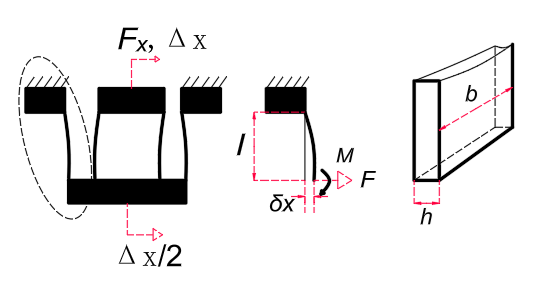
Figure 1: (a) Deformation of the CPF, (b) Dimensions of a Single Flexure, and (c) Cross-section
At the initial stage of the CPF, when an external force Fx is applied to the free end, the deformation appears as shown in Figure 1(a). The four flexure mechanisms in the structure are subjected to both force F and moment M. Considering the boundary conditions of rotational angles and translational motion, the following relationships can be derived [9,10]:
\( 0=\frac{F{l^{2}}}{2EI}-\frac{Ml}{EI} \) (1)
\( δx=\frac{F{l^{3}}}{3EI}-\frac{M{l^{2}}}{2EI} \) (2)
Here, \( δx \) represents the lateral displacement of a flexure structure [Figure 1(b)], E is the material’s Young’s modulus, and I=bh3/12 is the second moment of the cross-sectional area about the neutral axis [Figure 1(c)].
By combining equations (1) and (2), the following expressions can be obtained:
\( F=\frac{2M}{I} \) (3)
\( δx=\frac{F{l^{3}}}{12EI} \) (4)
Since the lengths l of the four flexures are identical, the relationship \( δx=Δx/2 \) holds, where \( Δx \) represents the unilateral displacement of the CPF. The stiffness of the CPF in this state can be calculated as:
\( {K_{1}}=\frac{{F_{x}}}{Δx}=\frac{2F}{2δx}=\frac{Eb{h^{3}}}{{l^{3}}} \) (5)
If the maximum moment Mmax is caused by flexure, the maximum stress \( {δ_{max}} \) on the material occurs at the edges of the cross-section and is determined by the material’s yield strength \( {σ_{y}} \) :
\( {σ_{max}}=\frac{{M_{max}}h/2}{I} \) (6)
The maximum moment is given by:
\( {M_{max}}=\frac{{σ_{max}}b{h^{2}}}{6} \) (7)
By combining equations (3), (5), and (7), the following expression is obtained:
\( Δx_{max}^{CPF}=\frac{{F_{max}}}{{K^{CPF}}}=\frac{{σ_{max}}{l^{2}}}{3Eh} \) (8)
Equation (8) indicates that under given material conditions, the maximum unilateral displacement \( Δx_{max}^{CPF} \) of the CPF depends on the length l and thickness h of the flexure material. To achieve greater displacements, the flexure structure must be designed to be longer and thinner.
2.2. Other Common CPF Systems
In addition to the CPF structure shown in Figure 1, other widely used CPF structures are illustrated in Figure 2.
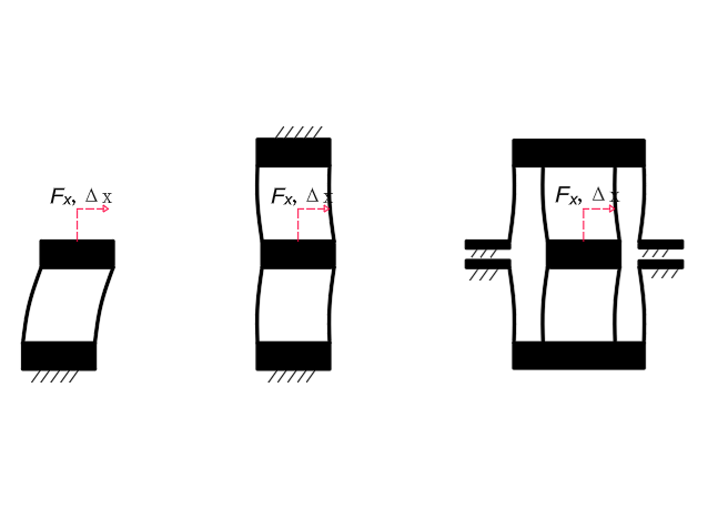
Figure 2: (a) CPF Structure 1, (b) CPF Structure 2, (c) CPF Structure 3
The CPF shown in Figure 2(a) is a serial combination of the flexure structures in Figure 1. Therefore, its stiffness can be calculated as:
\( 2{K_{1}}={K_{2}}=\frac{2Eb{h^{3}}}{{l^{3}}} \) (9)
Similarly, Figure 2(b) represents two of the flexures in Figure 2(a) arranged in parallel, while Figure 2(c) represents two flexures in Figure 1(a) arranged in parallel. Their stiffness values are:
\( {K_{3}}=\frac{4Eb{h^{3}}}{{l^{3}}} \) (10)
\( {K_{4}}=\frac{2Eb{h^{3}}}{{l^{3}}} \) (11)
3. Simulation Analysis
The main parameters of the structure in this simulation study are l = 20 mm, b = 10 mm, and h = 1 mm. Finite element analysis of the four CPF structures mentioned above was conducted using ANSYS software. The material used (Al) has the following specifications: Young’s modulus = 71 GPa, Poisson’s ratio = 0.33, and density = 2810 kg/m³.
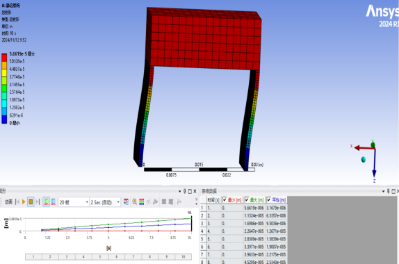
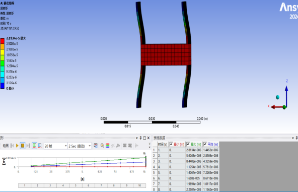

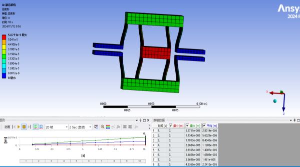
Figure 3: (a), (b), (c), and (d): Simulation Interfaces of Four CPF Systems
During the simulation, the finite elements of the flexible beams were first divided into segments of 0.5 mm (half of h). Then, specific planar sections were fixed to study the deformation process: in System (a), the lower planes of two flexible beams were fixed; in System (b), the upper and lower planes of four flexible beams were fixed; in System (c), the upper planes of two blue rigid bodies were fixed; and in System (d), the opposing planes of four blue rigid bodies were fixed. A force ranging from 0 to 10 N was applied to the red rigid body sections of the four flexible structures in 11 simulation calculations, and the maximum displacement was simulated. The simulated displacement was then compared with the calculated displacement through graphical analysis. Based on the simulation results, the stiffness was calculated, and the error between the simulated stiffness and theoretical stiffness was determined.
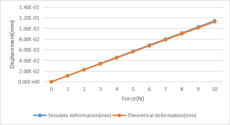
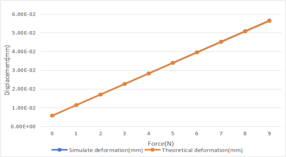
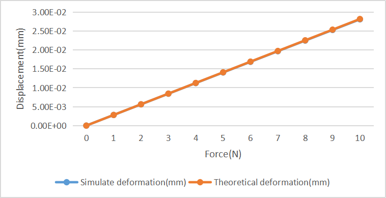
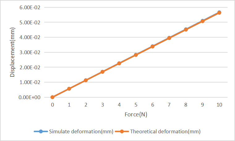
Figure 4: (a), (b), (c), and (d): Comparison of Simulated and Calculated Displacements for Four CPF Structures
As shown in Figure 3, the simulation results closely match the calculated results. The relative error in stiffness calculations further validates this conclusion. The errors between the simulated stiffness and the theoretical stiffness calculated using equation (5) for the four structures are as follows: -0.3836%, 0.3134%, -1.4639%, and -0.5595%. Since finite element analysis was used, it can be concluded that the theoretical analysis for the four structures is correct. If the number of finite elements is further increased, the error will be reduced even more.
4. Conclusion
This paper theoretically analyzed the force-displacement characteristics and stiffness of four CPF systems and validated the theoretical derivations through finite element simulation experiments. The explanation of the stiffness errors further supports the validity of the analysis. These four flexible mechanisms are widely used in engineering practices, and clarifying their theoretical formulas contributes to the deeper development of flexible systems. Admittedly, the flexible mechanisms covered in this paper are limited in type and feature simple structures, which preclude a more detailed description of their functionalities. Future research will delve deeper into this field, aiming to provide greater support for the development and application of flexible mechanisms, thereby bringing more convenience and innovation to human society.
References
[1]. Yu, J., et al. (2015). Progress in research on flexible mechanisms and their applications. Journal of Mechanical Engineering, 51(13), 16.
[2]. Wang, S., et al. (2005). Characteristics and applications of composite flexible hinge mechanisms. Optical Precision Engineering, Z1, 7.
[3]. Huang, Z. (2005). Research on flexible mechanisms and their application in biomimetic jumping mechanisms (Master’s thesis, Northwestern Polytechnical University).
[4]. Yang, Q., et al. (2007). Static analysis of a three-translation fully flexible parallel micro-motion robot mechanism. Transactions of the Chinese Society for Agricultural Machinery.
[5]. Han, Y., et al. (2014). Dynamic reliability analysis of flexible mechanisms based on support vector machines. Journal of Mechanical Engineering, 50(11), 86-92.
[6]. Jiang, J. (2023). Design of a bronchial diagnostic robot mechanism and study on the pose of the flexible end effector (Master’s thesis, Liaoning Technical University).
[7]. Zhang, J. (2009). Research on the basic theory and application technologies of flexible exoskeleton human-machine intelligent systems (Doctoral dissertation, Zhejiang University).
[8]. Yang, K. (n.d.). Vibration control and experimental study of flexible robotic arms (Doctoral dissertation, Beijing University of Posts and Telecommunications).
[9]. Xu, Q. (2012). New flexure parallel-kinematic micropositioning system with large workspace. IEEE Transactions on Robotics, 28(2), 478-491.
[10]. Awtar, S., & Parmar, G. (2013). Design of a large range XY nanopositioning system. In Proceedings of the ASME International Design Engineering Technical Conferences & Computers & Information in Engineering Conference (pp. 387-399).
Cite this article
Wang,H. (2025). Mechanical Modeling and Finite Element Analysis of Typical Compliant Mechanisms Based on Flexible Leaf Springs. Theoretical and Natural Science,86,150-155.
Data availability
The datasets used and/or analyzed during the current study will be available from the authors upon reasonable request.
Disclaimer/Publisher's Note
The statements, opinions and data contained in all publications are solely those of the individual author(s) and contributor(s) and not of EWA Publishing and/or the editor(s). EWA Publishing and/or the editor(s) disclaim responsibility for any injury to people or property resulting from any ideas, methods, instructions or products referred to in the content.
About volume
Volume title: Proceedings of the 4th International Conference on Computing Innovation and Applied Physics
© 2024 by the author(s). Licensee EWA Publishing, Oxford, UK. This article is an open access article distributed under the terms and
conditions of the Creative Commons Attribution (CC BY) license. Authors who
publish this series agree to the following terms:
1. Authors retain copyright and grant the series right of first publication with the work simultaneously licensed under a Creative Commons
Attribution License that allows others to share the work with an acknowledgment of the work's authorship and initial publication in this
series.
2. Authors are able to enter into separate, additional contractual arrangements for the non-exclusive distribution of the series's published
version of the work (e.g., post it to an institutional repository or publish it in a book), with an acknowledgment of its initial
publication in this series.
3. Authors are permitted and encouraged to post their work online (e.g., in institutional repositories or on their website) prior to and
during the submission process, as it can lead to productive exchanges, as well as earlier and greater citation of published work (See
Open access policy for details).
References
[1]. Yu, J., et al. (2015). Progress in research on flexible mechanisms and their applications. Journal of Mechanical Engineering, 51(13), 16.
[2]. Wang, S., et al. (2005). Characteristics and applications of composite flexible hinge mechanisms. Optical Precision Engineering, Z1, 7.
[3]. Huang, Z. (2005). Research on flexible mechanisms and their application in biomimetic jumping mechanisms (Master’s thesis, Northwestern Polytechnical University).
[4]. Yang, Q., et al. (2007). Static analysis of a three-translation fully flexible parallel micro-motion robot mechanism. Transactions of the Chinese Society for Agricultural Machinery.
[5]. Han, Y., et al. (2014). Dynamic reliability analysis of flexible mechanisms based on support vector machines. Journal of Mechanical Engineering, 50(11), 86-92.
[6]. Jiang, J. (2023). Design of a bronchial diagnostic robot mechanism and study on the pose of the flexible end effector (Master’s thesis, Liaoning Technical University).
[7]. Zhang, J. (2009). Research on the basic theory and application technologies of flexible exoskeleton human-machine intelligent systems (Doctoral dissertation, Zhejiang University).
[8]. Yang, K. (n.d.). Vibration control and experimental study of flexible robotic arms (Doctoral dissertation, Beijing University of Posts and Telecommunications).
[9]. Xu, Q. (2012). New flexure parallel-kinematic micropositioning system with large workspace. IEEE Transactions on Robotics, 28(2), 478-491.
[10]. Awtar, S., & Parmar, G. (2013). Design of a large range XY nanopositioning system. In Proceedings of the ASME International Design Engineering Technical Conferences & Computers & Information in Engineering Conference (pp. 387-399).