


1. Introduction
With the continuous increase in the number of large buildings in China, the demand for internal building transportation has also risen. Although a large number of advanced foreign technologies have been introduced into China’s elevator industry during this period, key elevator group control technologies have not yet been fully absorbed or implemented [1]. To address this issue, this paper designs an elevator system to improve the elevator industry in China, replacing traditional relays with PLCs for elevator control. Finally, through a comparative analysis, a relatively optimal retrofit solution is proposed, which is of great significance in advancing elevator technology in China.
The research value of this solution can be summarized in the following aspects:
(1) Enhancing Safety: The elevator system can improve overall safety performance through the initialization program, maintenance procedures, and anti-collision programs.
(2) Improving Efficiency: By constructing a group control algorithm, the elevator dispatching process is optimized, reducing resource waste and improving operational efficiency.
(3) Reducing Energy Consumption: The elevator system can control lighting, fans, and elevator calls based on passenger flow and elevator demand, thereby reducing energy consumption.
2. Composition and Function of the Elevator System
2.1. Hardware Components of the Elevator System
The elevator system primarily consists of the traction system, guiding system, elevator door system, car system, weight balance system, electric drive system, elevator control system, and safety protection system [2], as shown in Figure 1.
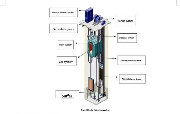
Figure 1: Composition of the Elevator System
The functions of each component are as follows [2]:
(1) Traction System: This is an elevator drive installed within the elevator shaft of a traction-type elevator. It includes a transmission device, a vertically positioned motor, a brake, and suspension components that provide vertical motion for the elevator chassis. It is lightweight under various operating conditions, with a full range of specifications, superior performance, reliability, durability, and high cost-effectiveness, capable of handling various types of cargo and adaptable to different building structures.
(2) Guiding System: During the operation of the elevator, the guiding system limits the freedom of movement of the car and counterweight, ensuring that both the car and counterweight can only move vertically along their respective guide rails without any lateral sway or vibration, ensuring smooth operation. Both the car and counterweight guiding systems consist of three parts: guide rails, guide shoes, and rail brackets.
(3) Elevator Door System: The elevator door system mainly consists of two types: the landing doors installed at the elevator shaft entrance and the car doors installed at the entrance of the elevator car. These doors can be divided into various types, such as center-opening doors, side-opening doors, vertical sliding doors, and hinged doors. The main components of the elevator door system include the car door, landing door, and the linkage mechanism.
(4) Car System: The elevator car is a box-like space primarily used for transporting people and goods. It generally consists of major components such as the car floor, car walls, car ceiling, and car doors. The structure of the car includes the car frame and the car body. The car frame bears the weight and provides the necessary counteracting force, so it must have a certain level of strength and flexibility. The car body forms the enclosed walls of the car space, with necessary openings for entry and ventilation, and no other openings (some countries require safety windows to be installed on the top of the car).
(5) Weight Balance System: The weight balance system helps the elevator car maintain relative balance, creating a weight difference between the car and counterweight within a certain working range, ensuring the smooth and normal operation of the elevator’s traction drive system.
(6) Electric Drive System: The electric drive system consists of a traction motor, a speed feedback system, a power supply module, and a speed control module. It is the power source for the elevator, driving its components to perform the necessary actions.
(7) Electrical Control System: The electrical control system primarily manages and processes signals related to the elevator’s traction motor, including start, deceleration, stop, direction of movement, floor selection, parking, floor display, floor station calls, car commands, safety protection, and door motor control.
(8) Safety Protection System: The safety protection devices in the elevator safety system typically consist of mechanical safety devices and electrical safety devices. However, some mechanical safety devices require electrical coordination and interlocking devices to ensure their actions and reliable operation. With advancements in science and technology, elevators continue to evolve. Various protection systems have been designed to address potential hazards such as squeezing, falling, and electric shock. Examples include overload protection systems, terminal overshoot protection systems, emergency stop safety protection systems, and more.
2.2. Signal Components of the Elevator System
The signal components of the elevator system primarily include input signals and output signals. Input signals refer to the signals detected by sensors distributed on each floor and within the elevator car, including external call signals and internal call signals. Output signals refer to the operational signals of the traction motor and the car indicator lights. The elevator receives various input signals to control movements such as up-and-down motion, deceleration, and direction change, while generating output signals to improve operational efficiency and user comfort. The distribution of internal sensors in the elevator is shown in Figure 2.
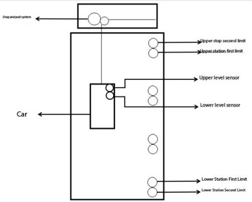
Figure 2: Distribution of Elevator Sensors
3. Design of the Six-Lift, Ten-Level Elevator System Based on PLC and WinCC
To facilitate modifications and improvements to the system, the program is divided into different modules, including the initialization module, indicator light module, elevator up-and-down operation and speed control module, elevator door control module, elevator maintenance and overload module, and group control module. Each module is introduced sequentially.
3.1. Elevator Initialization Module
In daily life, after each reboot, the elevator cannot accurately determine its current floor. In such cases, the elevator needs to undergo initialization. Depending on the target floor for initialization, the elevator may need to perform either an overshoot to the top or bottom floor. To ensure operational efficiency, when the target initialization floor is above the fifth floor, the elevator will move upward; otherwise, it will move downward. Additionally, when the elevator reaches the top or bottom limits during this process and contacts the first or second limit switches, the elevator's floor is set to the eleventh or ground floor. After that, the elevator moves to the target floor to complete initialization, and the elevator officially starts. The program segment is shown in Figure 3.
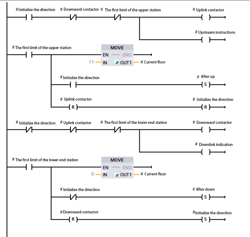
Figure 3: Initialization Program
3.2. Indicator Light Module
Different indicator lights within the elevator system are a crucial part of the elevator, as they not only help alleviate user anxiety and improve comfort but also represent the different states of various signals in the elevator. These signals are interactive, allowing users to engage with them. The primary signals include the elevator floor signal, elevator call signal, and manual elevator door open/close signal.
The elevator floor signal can be divided into the current direction of travel signal and the current floor signal. The former is represented by three possible displays: upward, downward, or no display. For displaying the floor signal, a seven-segment display is used. A commonly used seven-segment LED display consists of seven small LED light-emitting diodes. By controlling the on/off state of different LEDs, different characters can be displayed. The seven-segment display used in this paper is a common cathode display. The circuit diagram is shown in Figure 4, where the labels a, b, c, d, e, f, and g correspond to specific PLC output points.
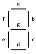
Figure 4: LED Circuit Diagram
The elevator call signal can be divided into external call signals and internal call signals. The external call signal refers to when a user calls the elevator to a specific floor, requesting it to stop and open its doors. The internal call signal refers to when a user inside the car operates the elevator to reach a specific floor in the correct direction. Usually, the elevator car is equipped with an operating panel, and for each floor, there is a button with an indicator light. When a user presses the button for a specific floor, if the elevator car is not already on that floor, the indicator light for the button will light up, indicating that the internal call signal has been registered. Once the elevator reaches the registered floor, the indicator light will turn off, indicating that the internal call signal has been cleared. The external call signals are realized through call buttons on each floor. Except for the top floor, which has only a down-call button, and the bottom floor, which has only an up-call button, all other floors are equipped with both up and down call buttons. The registration and clearing rules for the external call signal are the same as those for the internal call signal.
The manual elevator door open/close signal can be divided into the manual door open signal and the manual door close signal. These signals are mainly used in specific situations, such as: when the elevator needs to reopen its doors during the closing process, when the elevator doors need to close ahead of schedule during a stop, or when the elevator doors are manually operated during maintenance. When the open or close door button is pressed, and the door is not yet fully opened or closed, the corresponding indicator light will turn on, indicating that the door opening/closing process is in progress. When the door is fully opened or closed, the indicator light will turn off, indicating that the door opening/closing process has been completed.
3.3. Elevator Up-and-Down Operation and Speed Control Module
Principle of Elevator Up-and-Down Direction Control: When the elevator is not overloaded, under maintenance, and the floor door lock signals are in position, after receiving the corresponding call signal from a floor or an operation signal from the car, the elevator will activate the up or down contactor, simultaneously lighting the up direction indicator light, and resetting the reverse direction contactor and its indicator light. For example, when the elevator system receives an up signal that meets the conditions for upward movement, and the elevator doors are closed with no overload condition, the elevator will activate the up contactor, light the up indicator light, and reset the down contactor and the down indicator light. The program segment is shown in Figure 5.
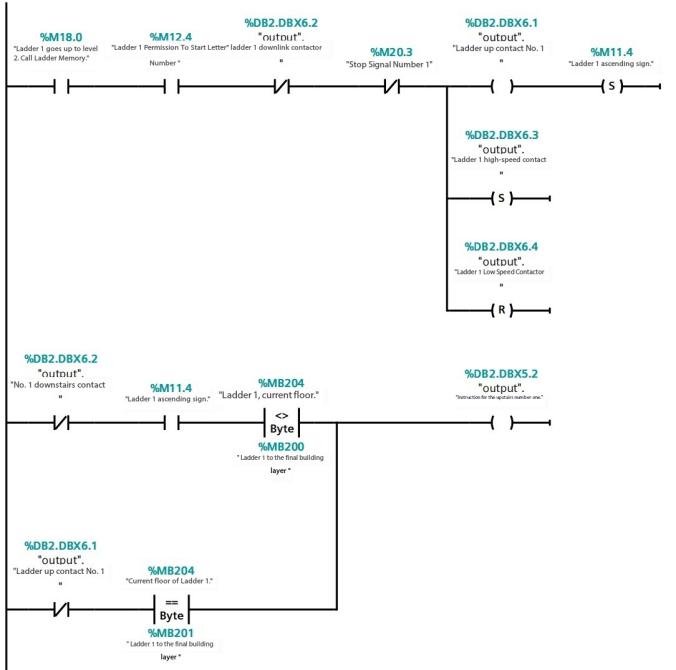
Figure 5: Elevator Upward Operation Program
Principle of Two-Speed Elevator Speed Control [3]: The elevator system referenced in this scheme is an AC two-speed elevator. The term "two-speed" is used to improve comfort during deceleration, and typically involves a two-speed cage-type asynchronous motor, where the speed changes in two stages during deceleration. During the elevator's startup process, in order to limit the startup current, reduce voltage fluctuations in the power grid, and decrease the acceleration during startup, the system usually includes resistors, reactance, or a combination of resistance and reactance in the stator of the motor to achieve reduced voltage starting. As the motor speed increases, the resistors and reactance are gradually cut out, allowing the elevator to gradually accelerate to a stable running speed. During startup, the system typically uses one or two stages to cut out resistors and reactance. During deceleration, the motor switches from high-speed to low-speed windings. To limit the braking current and deceleration speed and prevent excessive shock, the system typically uses two or three stages to cut out resistors and reactance. The symbol explanations are shown in Table 1.
Table 1: Symbol Explanations
SK | Uplink contactor | 1A | First acceleration |
XK | Downward contactor | 2A | First braking |
KK | High-speed contactors | 3A | Secondary braking |
MK | Low-speed contactors | 4A | Three-stage braking |
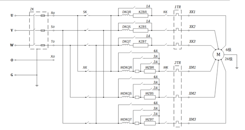
Figure 6: AC Two-Speed Elevator Main Drive System Circuit Diagram
As shown in Figure 6, taking the upward speed control as an example, when the elevator starts, the SK and MK contactors close, and the motor starts with an inductive reactance in the stator circuit. At this point, the starting torque is greater than the load torque, and the motor speed gradually increases. Approximately 50 ms later, the elevator enters the first acceleration state, the MK contactor opens, and the KK contactor closes, allowing the elevator to enter a steady-speed operation state. Before the elevator reaches its stop position, a change-speed signal is sent by the lower leveling sensor. The control circuit releases the KK contactor and closes the MK contactor, converting the elevator from high-speed operation to low-speed operation. To improve braking efficiency, the 1A contactor is first closed according to the time principle. Then, the 2A–4A contactors are closed in sequence according to the time principle, gradually reducing the speed of the elevator to improve passenger comfort during the stop. After receiving the lower leveling signal, the elevator reaches the leveling position, and the contactor de-energizes to apply the brake, completing the deceleration [4]. The program segment is shown in Figure 7.
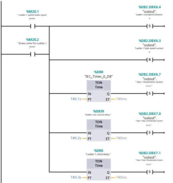
Figure 7: Elevator Speed Change Program
3.4. Elevator Door Control Module
The door control system is the first component users interact with when using an elevator, and it has historically been a point of injury in elevator accidents. Therefore, the door control program is crucial. When the elevator system receives an operational signal and reaches the designated floor, it will open the door to allow the user to enter or exit. At this point, the door-opening program begins. The door relay is activated, allowing current to pass through the coil and causing the motor to rotate in the forward direction. When the elevator door reaches the limit switch, the door-opening action is completed. After a five-second delay, the door-closing program begins. The door-opening relay is deactivated, and the door-closing relay is activated, causing the motor to rotate in reverse, starting the door-closing action. When the door reaches the limit switch, the closing action is completed. Additionally, to prevent the elevator doors from closing on people or objects, an infrared light curtain anti-collision device is used. When the light beam is obstructed by a person or object (i.e., when a signal is detected), the door-closing action is immediately halted. The door control programs are shown in Figures 8 and 9.
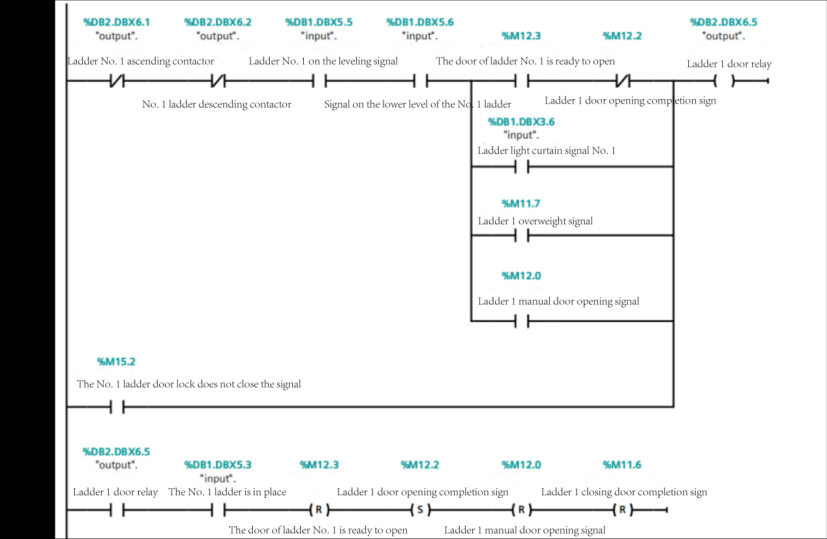
Figure 8: Elevator Door Opening Program
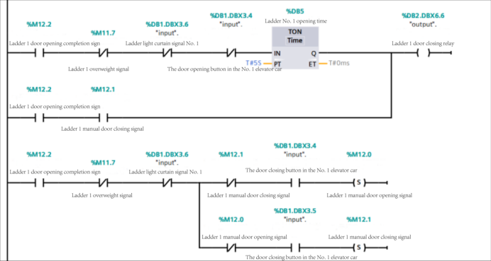
Figure 9: Elevator Door Closing Program
In addition to controlling the elevator door when picking up and dropping off users, this module is also used in other scenarios:
Door Opening Events:
(1) The elevator needs to reopen the door during the closing process.
(2) The elevator opens the door when it receives an external call signal while in standby mode.
(3) The elevator restricts door opening during automatic operation.
(4) The elevator door is opened when it is jammed or overloaded.
(5) The elevator door opens during maintenance.
Door Closing Events:
(1) The elevator closes the door in advance when stopped at a station.
(2) The elevator prevents the door from closing when it is jammed or overloaded.
(3) The elevator door closes when in maintenance mode.
3.5. Elevator Maintenance and Overload Modules [5]
Maintenance Module: To ensure the safety of elevator operation and extend its lifespan, regular maintenance is required. When the elevator receives a maintenance signal, this indicates the start of the maintenance process. At this point, the elevator door should be opened to allow staff to enter and perform maintenance inside the elevator. During maintenance, the elevator will stop accepting signals, i.e., it will pause operation. After maintenance is completed, the elevator will automatically execute the initialization program. Once the initialization is complete, the elevator will resume operation. The maintenance program segment is shown in Figure 10.
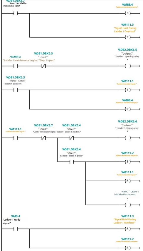
Figure 10: Maintenance Program
Overload Module: To ensure the safe use of the elevator, the rated weight capacity is specified during its design. The weight inside the elevator cabin is detected and measured by internal gravity sensors. If the weight inside the cabin exceeds the rated weight, the elevator’s door-opening relay is activated to prevent the door from closing. Additionally, the overload indicator light will illuminate, signaling to users that the elevator is overloaded. The program segment is shown in Figure 11.
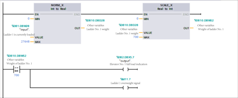
Figure 11: Overload Detection Program
3.6. Group Control Module
Since the elevator group control program is the most important part of the entire system, a detailed introduction to the group control principles will first be provided, followed by an explanation of the program design.
3.6.1. Elevator Group Control System
The elevator group control system primarily transmits the collected information from the slave PLC to the master PC, which then completes the selection and execution of floors and elevators, achieving the group control effect. Figure 12 shows the hardware structure diagram of an elevator group control system. The main components consist of the group controller, the console controller, and the motor drive. The elevator group control system is the core of the entire elevator group control. On one hand, it can collect external call signals based on factors such as the elevator’s current floor, direction of travel, cabin load, and passenger flow. It reasonably allocates external signals and sends them to the elevator control module. On the other hand, the group control module receives user information, sets parameters as needed, adds or removes functions, and outputs elevator-related information for user queries and monitoring.
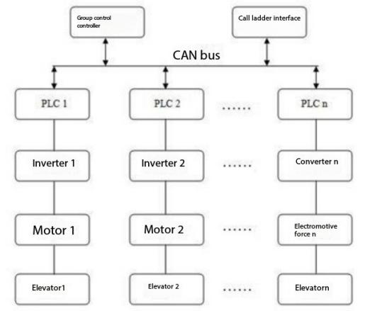
Figure 12: Hardware Structure of Elevator Group
The core task of the elevator group control module is to coordinate and optimize the elevator group dispatching. Once the call button is pressed, the elevator group control module immediately sends the call request and uses the group control algorithm to determine the optimal dispatching strategy, deciding which elevator will serve the request. Different strategies have different levels of efficiency. Therefore, selecting a well-performing elevator group control system dispatching strategy is essential.
3.6.2. Shortest Distance Scheduling Algorithm
To maximize elevator efficiency, [6] the optimal priority rule of the system is as follows: If there is an inner call signal on the same floor and in the same direction, the elevator that has already responded to this signal will take priority in responding to the external call. This principle helps reduce the number of stops, thereby reducing call time and improving elevator efficiency.
The algorithm used in this scheme is the Shortest Distance Scheduling Algorithm. The principle of this algorithm is that the elevator called should be the one closest to the call floor. Therefore, the core of the program is to calculate the minimum distance between the elevator and the call floor. The shortest distance is not the straight-line distance between the elevator’s current floor and the call signal floor, but rather the shortest distance that takes into account the elevator’s current direction of travel and any internal call floors. For example, if the up-call button on the 7th floor is pressed and there are two elevators on the 5th and 9th floors, one traveling upwards from the 5th floor and the other traveling downwards from the 9th floor, the straight-line distance to the 7th floor may appear the same for both elevators. However, the distance to respond to the 7th floor’s up-call is different. The elevator on the 5th floor only needs to travel two floors to reach the 7th floor, while the elevator on the 9th floor needs to descend to the 3rd floor before traveling upwards to the 7th floor. In this case, it is more reasonable to dispatch the elevator from the 5th floor.
Shortest Distance Module Design: Suppose elevator 1 is currently at floor
x1(x1 ≠ y), with the target floor y=5, and the travel direction is 𝑧 (where z=1 for upward, and z=0 for downward).
Taking the up-call on the 7th floor as an example, the current floor of the elevator and its direction of travel are combined into three cases:
(1) If the elevator is currently below the 7th floor and moving upwards, the actual distance to the target floor is: \( Y=|{x_{1}}-y| \) .
(2) If the elevator is above the 7th floor and moving upwards, assuming the up-target floor is the 10th floor and then returning downwards to the 1st floor, the actual distance is: \( Y=|10-{x_{1}}+9+y-1| \)
(3) If the elevator is moving downwards, with a target floor of 1st, the actual distance is: \( Y=|{x_{1}}-1+y-1| \)
Therefore, when the up-call button is pressed at a certain floor, the distance 𝑖 for elevator 1 to respond to this call is calculated as follows:
\( \begin{cases} \begin{array}{c} |{x_{1}}-y| {x_{1}} \lt y ,z=1 \\ |18-{x_{1}}+y| {x_{1}} \gt y, z=1 \\ |{x_{1}}+y-2| z=0 \end{array} \end{cases} \)
For a down-call signal on the 7th floor, three cases arise:
(1) If the elevator is currently above the 7th floor and moving downwards, the actual distance to the target floor is:
\( Y=|{x_{1}}-y| \)
If the elevator is below the 7th floor and moving downwards, assuming the down-target floor is the 1st, and then moving upwards to the 10th floor, the actual distance is:
\( Y=|18+{x_{1}}-y| \)
If the elevator is moving upwards, the actual distance is:
\( Y=|20-{x_{1}}-y| \)
Thus, when a down-call signal is pressed at a certain floor, the actual distance for elevator 1 to respond to this signal is: \( \begin{cases} \begin{array}{c} |{x_{1}}-y| {x_{1}} \gt y,z=0 \\ |18+{x_{1}}-y| {x_{1}} \lt y,z=0 \\ |20-{x_{1}}-y| z=1 \end{array} \end{cases} \)
Using these two piecewise functions, the actual distances of six elevators to the up-call signal are calculated, and the elevator with the shortest distance is selected to respond to the signal.
When an external call signal occurs, the actual distances of the six elevators to the call signal are calculated, and the MIN instruction is used to obtain the smallest value from these distances. The elevator closest to the target floor will then respond to the call signal. The shortest distance calculation program is shown in Figure 13, and the elevator call signal assignment flow is shown in Figure 14. Once the call signal is assigned, if any other elevator has an internal selection signal that reaches the floor first and is moving in the same direction as the call signal, this elevator will also cancel the external call signal response of another elevator. For example, if the up-call signal on the 5th floor is first responded to by elevator 2, and later elevator 2 stops due to other reasons (such as a passenger holding the door open button for a long time), then if elevator 1 arrives at the 5th floor first, it will cancel the external call signal response from elevator 2. [7]
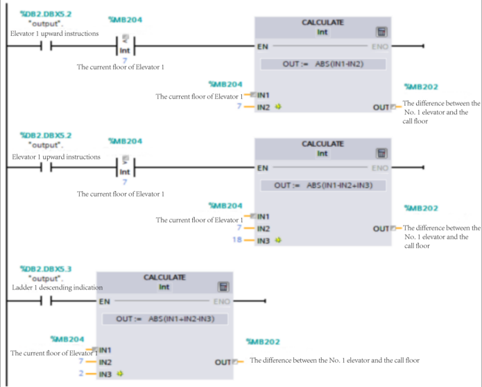
Figure 13: Shortest Distance Calculation Program
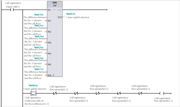
Figure 14: Elevator Call Signal Assignment Flow
4. WinCC Monitoring Screens
During the operation of an elevator, the input and output signals generated and controlled by the sensors and motors continuously change. To better and more intuitively understand the entire operational status of the elevator, the use of the Windows Control Center (WinCC) is necessary to meet this need. WinCC is a PC-based HMI/SCADA system under Siemens TIA architecture. It allows for the monitoring and control of on-site operational equipment, making the entire elevator operation process visual. Additionally, it provides operator control and monitoring of processes via a user interface, enabling functions such as data collection, equipment control, measurement, parameter adjustments, and various signal alarms. This facilitates the management of the elevator and repair during malfunctions, improving work efficiency.
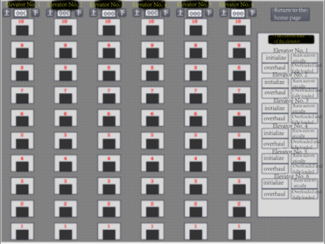
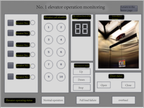
In this article, the WinCC screens are divided into four main screens: Initialization Floor Settings, External Call Status Monitoring, Single Elevator Operation Monitoring, and Elevator Status Overview. First and foremost, the Elevator Status Overview screen is the most important. It displays the status of each elevator. This screen also shows the floors of all six elevators, their current up or down status, the operation status of all elevators, the opening and closing of elevator cabin doors, and the current status of the sensors. Secondly, the Single Elevator Operation Monitoring screen provides detailed information for an individual elevator. Taking Elevator 1 as an example: when the elevator is moving upwards, the upward indicator light turns green, the corresponding call or internal selection signal light illuminates, and the motor starts. The normal operation indicator light is on. After reaching the designated floor, the upward indicator light goes out and the stop operation indicator light turns green.
The Elevator Status Overview is shown in Figure 15, while the Single Elevator Operation Monitoring for Elevator 1 is shown in Figure 16.
|
|
Figure 15: Elevator Status Overview | Figure 16: Single Elevator Operation Monitoring |
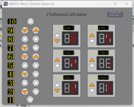
Upon downloading the PLC program to the S7-1200 and starting the simulation, we enter the WinCC debugging interface. From the WinCC monitoring screen on the host computer, we can obtain information such as the operation status of the six elevators, floor information, and external call signals. As shown in Figure 17, the monitoring screen reveals that there are down-call signals on the 9th, 7th, 6th, 4th, and 2nd floors, and up-call signals on the 6th and 9th floors. Furthermore, Elevators 2, 3, 4, and 6 are in the upward state, while Elevators 1 and 5 are in the downward state, with each elevator's respective floor shown.
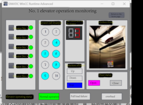
In addition, we can also obtain real-time internal call signals and operating statuses for a specific elevator from the WinCC monitoring screen. As shown in Figure 18, Elevator 1 has internal call signals for floors 4, 5, 6, 8, and 9, and is currently in the door-open state on the 3rd floor.
|
|
Figure 17: External Call Status Monitoring | Figure 18: Elevator 1 Operation Monitoring |
5. Elevator Simulation and Results
To verify the feasibility of the proposed solution, this paper uses the EET Pro (Elevator Simulation Professional) software. This software effectively tests the feasibility of the solution.
5.1. Simulation Environment
The elevator simulated by EET is nearly identical to real-world elevators. It can simulate the flow of people in daily life by importing pre-written project files and can also simulate various emergency situations such as maintenance or overload. This meets the requirements for verifying the feasibility of the solution, as shown in Figure 19. The simulation interface is divided into five parts:
(1) 3D Display Area: This is the three-dimensional view of the elevator. The size and direction can be adjusted using the mouse for easier observation.
(2) Function Selection Area: This is the control area of the software, consisting of various buttons, such as the start and stop buttons for elevator simulation and the simulation result configuration button.
(3) Operation Signal Display Area: This area includes the direction indicators for each elevator's operation, the current floor display, cabin lighting indicators, fan indicators, and malfunction signal indicators. This area only displays information and does not support operational responses.
(4) Floor Call Signal Area: This area includes the up-call and down-call buttons for each floor. For terminal stations, only one direction of call button is available. Pressing a button will change the corresponding input signal.
(5) Cabin Floor Selection Signal Area: This includes the internal floor call and door open/close buttons in the elevator cabin. Pressing a button will change the corresponding input variables.
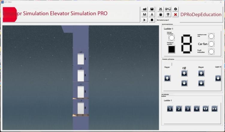
Figure 19: Simulation Operation Interface
5.2. Simulation Results
To better verify the feasibility of the solution, we import a project file into EET, with a total time of 30 minutes and a total of 500 people. The final evaluation results provide several metrics, such as the basic functional logic during the initialization phase, as well as passenger flow testing metrics, including the number of passengers transported, the average elevator ride time, the average wait time, and the long wait rate. The more passengers transported, the better; conversely, the shorter the average elevator ride time, the average wait time, and the lower the long wait rate, the better.
As shown in Figure 20, the basic functional logic during the initialization phase was fully met. The number of passengers transported was 488, the average elevator ride time was 56.57 seconds, the average wait time was 25.21 seconds, and the long wait rate was 9%. These results sufficiently demonstrate the feasibility of the solution.
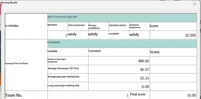
Figure 20: Evaluation Results Dialog Box
These results are mainly achieved through the improvement of the initialization and passenger loading phases of the program, as well as the shortest distance scheduling algorithm in the group control program. The improved operation programs for individual elevators ensure the safety and efficiency of each elevator’s operation, while the group control program provides the optimal solution for current passenger allocation, allowing for good results within 30 minutes.
6. Conclusion
This paper designs the functions of various elevator systems and implements the required functionalities for each program module. A comprehensive elevator system plan suitable for six elevators in a ten-story building is proposed. Based on the passenger flow model simulation results, it is demonstrated that the group control system can effectively improve elevator operation efficiency and promote energy conservation and emission reduction, thus achieving the design objectives of the program. The group control algorithm presented in this paper is the shortest distance scheduling algorithm, which has shown significant advantages in various fields, especially in elevator scheduling systems. This algorithm can reduce passenger waiting times, enhance the passenger experience, improve system response speed, increase overall efficiency, decrease energy consumption, save costs, and is easy to implement and expand, making it convenient for future management. These advantages make the shortest distance scheduling algorithm an important and effective scheduling method in elevator control systems.
References
[1]. Yue Zhu, Intelligent Elevator Group Control System for Residential Communities Based on Fuzzy Control, [D] Shenyang: Shenyang University of Technology, 2008.
[2]. Cangcheng Feng, Design and Research of PLC-Based Elevator Group Control System, [D] Qingdao University of Science and Technology, 2019.
[3]. Jiasheng Chen, Elevator Structure Principles and Installation Maintenance (5th Edition), [M] Beijing: Mechanical Industry Press, 2012.
[4]. Xinlin Cao, Research on the Composition and Design of Elevator Mechanical Systems, [J] Journal of Jiamusi Vocational College, 2019(12): 209+211.
[5]. Fan Zhang, A Brief Discussion on the Importance and Considerations of Installing Elevators in Existing Buildings, [J] Science and Technology Innovation and Application, 2016(31): 298.
[6]. Ningning Jia, Liping Gao, Weihua Yuan, et al., Research on Elevator Energy-Saving Renovation Issues — A Case Study of Nantong City, [J] Science and Technology and Innovation, 2024(04): 143-145. DOI: 10.15913/j.cnki.kjycx.2024.04.041.
[7]. Caicai Chai, Ping Tang, Ling Wang, et al., Design of Elevator Electrical Control System Based on PLC, [J] Modern Manufacturing Technology and Equipment, 2023, 59(12): 63-65. DOI: 10.16107/j.cnki.mmte.2023.0795.
Cite this article
Kan,W. (2025). Design of a Six-Lift, Ten-Level Elevator System Based on PLC and WinCC. Theoretical and Natural Science,87,319-333.
Data availability
The datasets used and/or analyzed during the current study will be available from the authors upon reasonable request.
Disclaimer/Publisher's Note
The statements, opinions and data contained in all publications are solely those of the individual author(s) and contributor(s) and not of EWA Publishing and/or the editor(s). EWA Publishing and/or the editor(s) disclaim responsibility for any injury to people or property resulting from any ideas, methods, instructions or products referred to in the content.
About volume
Volume title: Proceedings of the 4th International Conference on Computing Innovation and Applied Physics
© 2024 by the author(s). Licensee EWA Publishing, Oxford, UK. This article is an open access article distributed under the terms and
conditions of the Creative Commons Attribution (CC BY) license. Authors who
publish this series agree to the following terms:
1. Authors retain copyright and grant the series right of first publication with the work simultaneously licensed under a Creative Commons
Attribution License that allows others to share the work with an acknowledgment of the work's authorship and initial publication in this
series.
2. Authors are able to enter into separate, additional contractual arrangements for the non-exclusive distribution of the series's published
version of the work (e.g., post it to an institutional repository or publish it in a book), with an acknowledgment of its initial
publication in this series.
3. Authors are permitted and encouraged to post their work online (e.g., in institutional repositories or on their website) prior to and
during the submission process, as it can lead to productive exchanges, as well as earlier and greater citation of published work (See
Open access policy for details).
References
[1]. Yue Zhu, Intelligent Elevator Group Control System for Residential Communities Based on Fuzzy Control, [D] Shenyang: Shenyang University of Technology, 2008.
[2]. Cangcheng Feng, Design and Research of PLC-Based Elevator Group Control System, [D] Qingdao University of Science and Technology, 2019.
[3]. Jiasheng Chen, Elevator Structure Principles and Installation Maintenance (5th Edition), [M] Beijing: Mechanical Industry Press, 2012.
[4]. Xinlin Cao, Research on the Composition and Design of Elevator Mechanical Systems, [J] Journal of Jiamusi Vocational College, 2019(12): 209+211.
[5]. Fan Zhang, A Brief Discussion on the Importance and Considerations of Installing Elevators in Existing Buildings, [J] Science and Technology Innovation and Application, 2016(31): 298.
[6]. Ningning Jia, Liping Gao, Weihua Yuan, et al., Research on Elevator Energy-Saving Renovation Issues — A Case Study of Nantong City, [J] Science and Technology and Innovation, 2024(04): 143-145. DOI: 10.15913/j.cnki.kjycx.2024.04.041.
[7]. Caicai Chai, Ping Tang, Ling Wang, et al., Design of Elevator Electrical Control System Based on PLC, [J] Modern Manufacturing Technology and Equipment, 2023, 59(12): 63-65. DOI: 10.16107/j.cnki.mmte.2023.0795.