


1. Introduction
As technology advances, the automotive industry relentlessly seeks methods to enhance vehicle efficiency and mitigate environmental impacts, with a goal to increase fuel efficiency by 50% and reduce carbon emissions by 30% by 2030. Among these, the integration of advanced energy recovery technologies stands out as a particularly promising approach. This paper comprehensively examines the current state of energy recovery technologies, which are ingeniously designed to capture and convert waste energy into usable power, thereby boosting vehicle efficiency and optimizing energy utilization. The environmental impact of traditional internal combustion engine vehicles, coupled with the escalating demand for sustainable mobility solutions, underscores the importance of addressing this problem. Energy recovery systems offer a promising solution by enhancing vehicle efficiency and reducing emissions. This review aims to provide insightful perspectives on overcoming the environmental challenges posed by conventional vehicles, while also highlighting the potential of energy recovery system to contribute significantly to the development of more efficient and eco-friendly vehicles, promoting a greener and more sustainable future. This investigation into various energy recovery technologies examines different approaches to address the inefficiencies and the implementation feasibility in current systems and highlights the diverse methodologies employed by different researchers.
The first energy recovery technology gaining significant attention is regenerative braking. Vyacheslav Rakov addresses the problem of inefficient energy recovery in urban driving conditions due to frequent braking [1]. It aims to determine the optimal characteristics of braking energy recovery systems to maximize energy savings and improve vehicle efficiency in cities. Armenta-Déu focuses on inefficiencies in current kinetic energy recovery systems and the need for optimized algorithms to convert kinetic energy into electrical energy effectively [2]. Additionally, Yang seeks to quantify energy savings and the economic impact of implementing regenerative braking in converted electric vehicles, addressing inadequate control strategies and the need for comprehensive models considering motor losses and braking force distribution [3]. The methodology involves both theoretical analysis and practical testing, developing models to predict energy recovery potential based on various driving scenarios, and validating these models through experimental tests on vehicles equipped with regenerative braking systems. It highlights advancements in regenerative braking technology, energy storage systems like batteries and supercapacitors, and motor control strategies.
The second technology is a flywheel recovery system. The latest research on flywheel energy storage systems (FESS) focuses on improving their efficiency and applicability in various fields such as renewable energy integration and transportation. Research by Olabi [4] highlights the growing relevance of FESS in supporting grid stability and improving the use of renewable energy. Known for its fast response times and high power capacity, FESS is suitable for grid applications to stabilize power quality and effectively manage short-term energy fluctuations. Xu [5]'s comments further elaborate on the technological development of FESS, particularly in terms of material innovation and control strategies. Advances in magnetic bearings and composites are critical to reducing friction and improving system efficiency. These innovations not only improve the operational efficiency of FESS, but also extend the service life of FESS and reduce the need for maintenance. Xu's analysis highlights the importance of optimizing FESS components to meet the high demands of modern energy systems, especially in applications that require rapid energy injection, such as grid balancing and emergency power supplies.
The third Thermoelectric generator can be named one of the most difficult but also most promising energy convert technology. The thermoelectric effect is direct conversion of temperature difference to electric voltage. The thermoelectric generator is a solid device that use thermoelectric effect to transfer heat to electric energy. It is like internal combustion engine but no moving part and small enough to but multiple devices into the same automobile vehicle. Thermoelectric effects (the Seebeck effect and Peltier effect) that are mutual energy conversion between thermal and electrical energy solve these problems. The average automobile fuel efficiency is 25% under average driving conditions; 70% of the energy is dissipated in coolant or exhaust gases. Wan et al. [6]explored the effects of the location of thermoelectric coolers. A cooler placed directly above the head optimally increased thermal comfort. However, the study was conducted by targeting only the driver’s seat, and the installation location was not considered.
Among the thermodynamic cycles, the fourth the Rankine cycle can be named one of the most essential and widely used in electrical power generation in steam power plants. This cycle is known by the name Rankine cycle in honor of the Scottish engineer William John Macquorn Rankine and it effectively fulfills the generation of mechanical energy out of heat that in turn makes electricity. The knowledge of the Rankine cycle is central to the progress of power making innovation, especially on the present times when efficiency is quite an overriding factor coupled with sustainability considerations. The objectives of this essay include analysis of Rankine cycle from perspective of energy conversion efficiency, concern to the feasibility of the Rankine cycle, and impact upon environment in order to give the perspective of the Rankine cycle to the contemporary power generation [7].
The fifth mechanism is an electric turbocharger. Improving engine performance while maintaining environmental sustainability has become a critical challenge in automotive engineering. Conventional turbochargers enhance engine efficiency but struggle with responsiveness to transient power demands. Research into electric turbochargers, such as studies by Dimitriou [8] and Wagino [9], shows that integrating electric control devices can improve responsiveness and performance, especially in small-displacement engines and fuel cell systems. Capata [10] proposes a mild hybrid powertrain that generates electricity from waste energy, addressing range anxiety in pure electric vehicles and reducing emissions. This study highlights the design and potential of electric turbochargers to overcome conventional system limitations and advance sustainable vehicle technologies.
This study will discuss five types of energy recovery devices, namely regenerative crushing, mechanical flywheel, thermoelectric, Rankine cycle and electric turbochargers, around modern commuter transportation, energy recovery efficiency and implementation feasibility. The above part briefly introduces these five energy recovery methods, and proposes the research purpose. These five aspects will be discussed in the following chapters. In the following discussion section, this paper will explore the role and value of existing science and technology in energy recovery from multiple perspectives, including data analysis, logical deduction, theoretical deduction, etc., and summarize and analyze its basic principles. The main focus is to compare the efficiency of energy recovery in different situations and to evaluate the feasibility of the implementation of the equipment on electric vehicles and hybrid trams, among others. The purpose of this paper is to collect and summarize the relevant data of the past ten years, give a comprehensive overview of the current technical basis, analyze the opportunities and challenges facing the automotive industry, and provide references for its further development.
Research Question
Can the integration of energy recovery technologies improve the overall efficiency and environmental sustainability of commuter vehicles to reduce fuel consumption and greenhouse gas emissions?
Research Hypothesis
The interplay of modern energy recovery technologies will improve overall vehicle efficiency, such as the distance a hybrid vehicle can travel on the same amount of energy. In addition, a variety of energy recovery technologies interact, and the selection of appropriate recovery devices is very important in different vehicles, reflecting the implementation of recycling technology.
2. Discussion
2.1. Regenerative braking
Regenerative braking is a process in which a portion of a vehicle's kinetic energy, typically lost as heat energy by friction on the brake pads during conventional braking, is captured and stored for future use. This system redirects the energy that would be dissipated by friction brakes into a short-term storage system, such as a battery or capacitor, during deceleration. When the vehicle requires acceleration, the stored energy is converted back into kinetic energy, thereby propelling the vehicle without consuming additional fuel. The efficiency of regenerative braking systems depends on factors such as the type of energy storage, drivetrain efficiency, drive cycle, and vehicle weight. This technology is particularly beneficial in urban driving scenarios with frequent stops and starts, such as buses, taxis, and delivery vans, where a large amount of reclamation occurs to significantly reduce energy consumption and improve fuel efficiency. For regenerative braking to be cost-effective, the savings in prime energy must outweigh the initial costs and any size or weight penalties of the system. The energy storage unit must be efficient, durable, and capable of handling high power levels, making regenerative braking a vital component in enhancing the overall efficiency of electric and hybrid vehicles [11]. As shown in figure 1, this is a diagram of an electric vehicle powertrain. It demonstrates the flow of mechanical, electrical, and communication signals within the system.
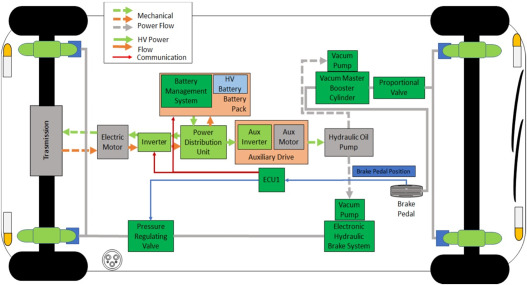
Figure 1: Braking control system for a rear-wheeled vehicle [1]
The paper investigates the impact of regenerative braking on the overall energy consumption of an electric vehicle, focusing on the efficiency with which the technology converts waste energy into usable electrical energy and the rate of energy recovery under various real-world operating conditions. The study by Rakov addresses the inefficiency in energy recovery due to a lack of in-depth analysis of energy loss mechanisms during electric braking. The proposed solution involves retrofitting a vehicle with a regenerative braking system and conducting empirical tests over 32 days to measure energy consumption with and without the system [11]. Additionally, a dual-motor regenerative braking system with an optimized control strategy is proposed by Yang to maximize energy recovery by minimizing motor losses and optimizing the distribution of braking forces between the front and rear axles. An accurate motor model was developed to analyze various losses during braking, and a motor control strategy based on the principle of minimum loss was designed. The study established a combined efficiency model and optimized the continuously variable transmission (CVT) speed ratio for different conditions, proposing a new control strategy for optimal braking force distribution considering regulatory constraints [2].
The results from Rakov indicated that the average energy consumption with regenerative braking was 145.26 Wh/km, compared to 154.79 Wh/km without it, demonstrating a reduction in energy consumption by approximately 6.16% [1]. Simulation results under typical operating conditions and the New York City Cycle (NYCC) showed that the proposed control strategy improved the energy recovery rate by 1.18% over traditional braking strategies. The discussion highlighted the significance of these findings, emphasizing that regenerative braking substantially improves energy efficiency and offers potential economic benefits, such as reduced energy costs and increased vehicle range. Efficient motor control and optimal braking force distribution were identified as key factors in enhancing energy recovery. The study concludes that implementing regenerative braking in electric vehicles can significantly reduce energy consumption, enhance efficiency, and provide economic advantages. The proposed dual-motor regenerative braking system and control strategy demonstrate significant improvements over conventional methods, suggesting that optimizing motor efficiency and braking force distribution can lead to better energy utilization in electric vehicles.
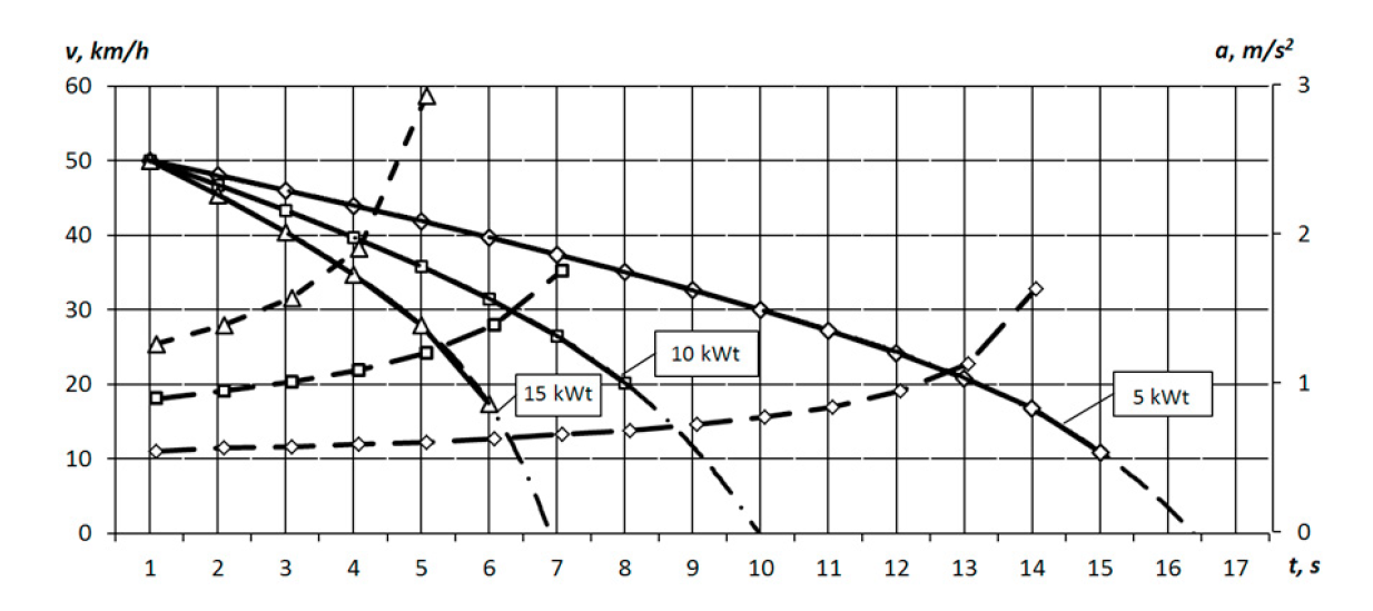
Figure 2: Results of the Deceleration profiles for a vehicle weighing 1340 kg, maintaining a constant regenerative braking power [1]
The study by Armenta-Déu examines the application and feasibility of integrating regenerative braking into electric vehicles, focusing on the efficient conversion of kinetic energy into electrical energy to extend driving range [1]. One solution involves using Brushless DC (BLDC) motor technology with an independent switching scheme, designed and implemented through a BLDC motor control system utilizing pulse-width modulation (PWM) and independent switching for efficient energy recovery during braking [3]. In addition, the paper addresses optimizing kinetic energy recovery by proposing a theoretical analysis of recovery algorithms and conducting experimental tests on electric vehicles. The methodology includes developing algorithms based on kinetic energy equations and validating them through data collection from urban and intercity routes, comparing theoretical predictions with real-world data from the vehicle's control unit. This dual approach aims to effectively convert kinetic energy, particularly during deceleration and route descents, into electrical energy to recharge the vehicle's battery, enhancing the practical integration of regenerative braking technology into existing vehicle designs [12].
The application of regenerative braking in electric vehicles with BLDC motors demonstrated a potential increase in driving range by up to 15%. The results showed that the regenerative braking system was effective in converting kinetic energy into electrical energy, achieving an average efficiency of 57.3%, though theoretical predictions did not fully match experimental data, indicating some inefficiencies. The discussion emphasized the challenges and benefits of integrating regenerative braking with BLDC motors, underscoring the importance of precise control and energy management to maximize energy recovery. It also analyzed discrepancies between theoretical and experimental results, suggesting improvements in the system and optimizing energy recovery algorithms for different driving conditions. The study concludes that while regenerative braking systems significantly enhance energy recovery and sustainability in electric vehicles, there is room for improvement in their efficiency. Optimizing these systems can lead to better energy conversion, extended driving ranges, and overall improved performance, making electric vehicles a more viable alternative to conventional internal combustion engine vehicles.
2.2. Mechanical flywheel
As shown in figure 3, a Flywheel Energy Storage System (FESS) converts electrical energy into kinetic energy, which is stored in a high-speed rotating flywheel. The system operates in three modes: charging, discharging, and standby. Energy storage is proportional to the square of the flywheel's angular velocity and its moment of inertia. The shape and material of the flywheel significantly impact its energy storage capacity. The maximum operational speed is determined by the tensile strength of the rotor material, ensuring the stress is below the material's limit. FESS offers efficient, controllable energy storage and release, making it advantageous for various applications [13].
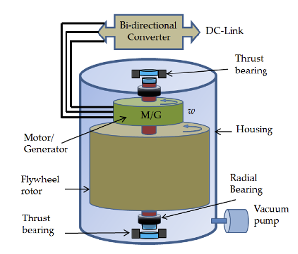
Figure 3: Structure and components of a flywheel [13]
Table 1: Comparison of the main energy storage method sand features [14]
Energy Storage Methods and Technologies | |||||
Features | Compressed Air Energy Storage | Chemical Battery Energy Storage | Superconducting Magnetic Energy | Supercapacitor Energy Storage | Flywheel Energy Storage |
Efficiency(%) | 40~60 | 70~80 | 80~95 | 80~95 | 85~95 |
Specific energy | — | 3~15 | 1~10 | 0.2~10 | 5~150 |
(Wh/kg) |
|
|
|
|
|
Specific power | — | 100~700 | 1000 | 7000~18,000 | 180~1800 |
(W/kg) |
|
|
|
|
|
Charging time | hours | hours | hours | minutes | minutes |
Discharge time | 1~20h | 1m in~ hours | 10 ms~15 min | 0.1s~1min | 15s~15 min |
Discharge depth | deep | shallow | deep | deep | deep |
Response time | minute | milliseconds | milliseconds | milliseconds | milliseconds |
Service life (Year) | >20 | 3-15 | >20 | >20 | >20 |
Maintenance |
|
|
|
|
|
cycles | frequent | <6 months | frequent | >10 years | >10 years |
Operating | 35~50 | -10~+300 | 4.2~77K | -30~+50 | -40~+50 |
temperature (°C) |
|
|
|
|
|
Environment | high | medium | extremely high | high | low |
requirements |
|
|
|
|
|
Environmental | no contamination | contamination | no contamination | no contamination | no contamination |
features |
|
|
|
|
|
The study by Peña-Alzola examines the need to improve the energy conversion efficiency of flywheel energy storage systems (FBESS) in power quality management and hybrid power systems. The proposed solutions include the manufacture of high-speed flywheels using advanced materials, the use of permanent magnet synchronous motors (PMSM) and variable reluctance motors (VRMs) to reduce losses, and the integration of magnetic bearings to minimize friction and wear. In addition, the bidirectional power converter using pulse width modulation (PWM) improves the energy conversion efficiency. These optimizations improve efficiency, reliability, and suitability for high-cycle applications, resulting in better power quality management and hybrid system performance, while achieving significant energy savings and operational benefits. In addition, the article by Yan solves the inefficiency problem caused by the mismatch between power supply and demand. The proposed solutions include an integrated flywheel energy storage system (FESS) to store and reuse excess energy and improve energy conversion efficiency through a variable frequency drive scheme. This method reduces the number of times energy is converted and improves the energy storage density of FESS. The system reduced installed power (the total power capacity installed in a facility, machine, or system, measured typically in kilowatts or horsepower) by 41.9%, demonstrating its effectiveness [15,16].
Integrating advanced components has increased the energy conversion efficiency of flywheel energy storage systems (FBESS) to over 85%. High tensile strength composites allow for higher speeds and greater energy storage density, while PMSM and VRMs reduce rotor loss. Bidirectional power converters with PWM and magnetic bearings further minimize energy loss and improve reliability. These enhancements make FBESS ideal for applications requiring frequent charge and discharge cycles, such as uninterruptible power supplies and hybrid power systems. Integrating a flywheel energy storage system (FESS) into the hydraulic power unit significantly improves energy efficiency. Tests show the new system runs smoothly at low load and effectively stores energy at high load. Experimental data indicate a 41.9% reduction in installed power, a 53% increase in energy utilization, thus significant energy savings. The study emphasizes that higher operating speeds enhance the flywheel's power output and energy provision, and combining FESS with variable frequency drives (VFD) improves energy storage density and performance [15,16].
Implementing energy storage using flywheel systems in rural electrification is challenging due to high costs, maintenance requirements and the need for reliable, efficient and environmentally friendly solutions. Flywheel energy storage systems (FESS) offer high energy density, efficiency and environmental friendliness, making them a suitable alternative to conventional batteries, especially in isolated microgrids. Advances in FESS technology, including novel composite materials, superconducting magnetic bearings, and high-speed motors, aim to create more compact and efficient systems and assess economic viability through net present value (NPV) analysis [17,18].
As shown in figure 4 and 6, the feasibility of implementing a Flywheel Energy Storage System (FESS) in urban rail transit was evaluated through a series of simulations and control strategy tests. As shown in figure 5, the FESS efficiently manages energy by storing braking energy and feeding it back during startup, which helps stabilize the voltage and frequency of the traction microgrid. An improved control strategy based on multi-threshold voltage and current feedback was employed, ensuring robust and rapid response under various operational conditions. MATLAB simulations verified the system's ability to maintain bus voltage stability, reduce bus voltage fluctuation to 2.1%, and improve response speed by 13.3%, demonstrating the effectiveness of the proposed methods and confirming the system's feasibility for practical implementation [17,18].

Figure 4: TOSA electric bus [18]
Figure 5: Electric bus energy consumption model system components [18]
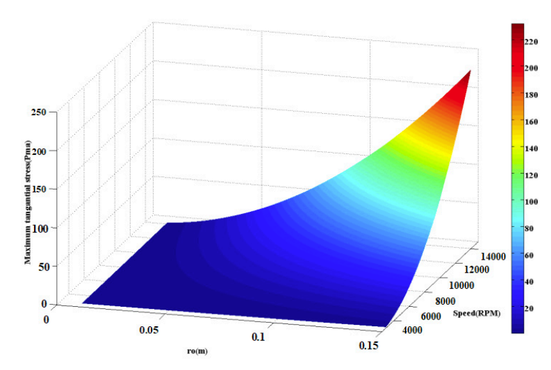
Figure 6: The maximum mechanical stress of the flywheel disk [18]
2.3. Thermoelectric
The current thermoelectric unit for automobiles mostly takes heat from the exhaust pipe. The exhaust gas takes heat from the engine and moves out of it. This heat is considered useless, and the unit will reuse it and convert it to electricity. However, according to this system, it will be stored in a battery. The battery can be used for air conditioning in cars and become an extra power station to charge your electric items, and your GPS in the car. In Hybrid vehicles, the generators can charge the battery for the energy resource for the electric motor.
ICE- Internal combustion engine
TEG- thermoelectric generator
APU- auxiliary power unit
EEV- extended-range electric vehicle
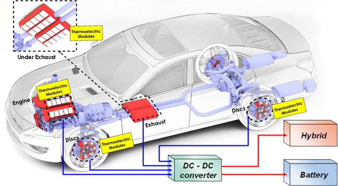
Figure 7: Structure of the thermoelectric system embedded in an automobile [19]
The study by Yi et al. examines that the Energy conversion efficiency in current technology was quite poor. The problem is that 30-40% of the energy from the engine is released with exhaust gas and to make the generator have a better working environment, a higher speed is required for the vehicle. According to one of the experiments, the average output power and conversion efficiency of the thermoelectric generator system was 45 W, 130 W, and 230 W and 1%, 1.6%, and 1.7% when the vehicle reached 48.3 km/h, 80.5 km/h, and 112.6 km/h [6]. This system could be efficient during high-speed driving. Even in that situation, the energy conversion efficiency was terrible. The solution to this problem could be to optimize the structure of the thermoelectric module and heat exchangers and change the structure of the heat exchanger.
By using a non-uniform hot-side heat exchanger, the result is greatly improved. The results showed that 41–75% of net power output enhancement could be obtained by using a heat exchanger with a longitudinal vortex generator. The Reynolds number and hot-side air temperature significantly affected TEG's net power output [20]. In my opinion, the shape is the most important parameter. The shape itself also allows heat from the exhaust to keep in the generator long enough to convert and therefore increase the efficiency. The other way to improve efficiency and keep heat energy longer in the generator is to add a strengthening element to it, such as a fin, a vortex generator, a heat pipe, or foam metal [6]. These add-on parts will increase their performance and some of them could even reduce exhaust noise.
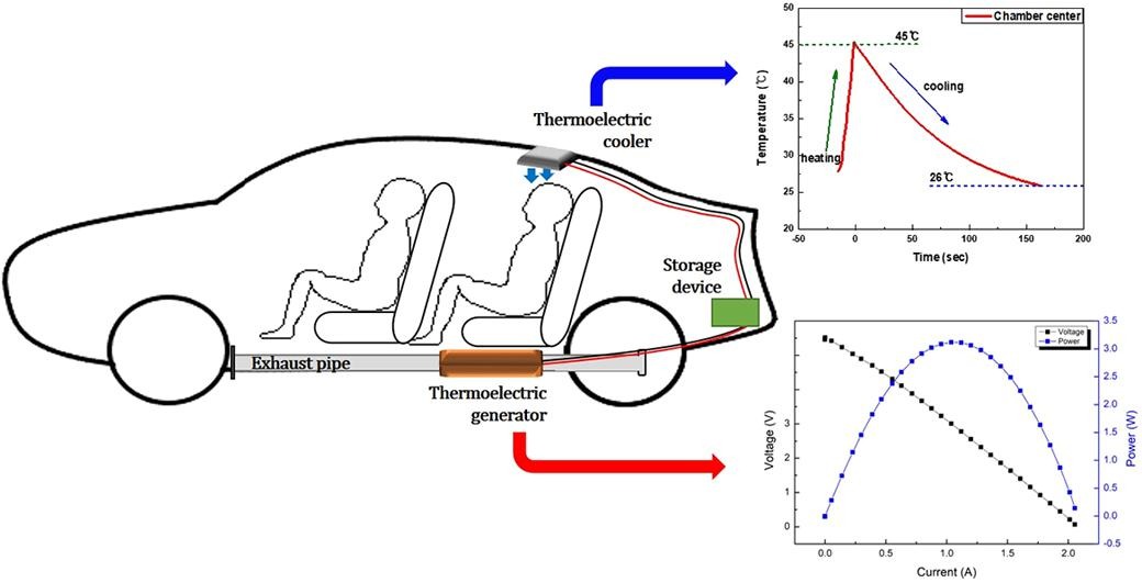
Figure 8: One way to use the thermoelectric generator in an automobile [21]
What about using a turbo to direct using heat energy generated by the engine? This is possible. The way that turbo works is by using wasted gas produced by the engine and spinning the blades to mix with fresh air to push through the engine to give it extra horsepower and improve fuel efficiency. If we could extend another shaft to a generator to make it. this might be possible, but the problem is the size. Right now, the thermoelectric generator turbine is too big, and even an airplane is unable to fit it on its turbine engine. The ICE will be difficult to apply. The TEG, together with the engine and electric generator, form a TEG integrated auxiliary power unit (APU). The electric output of the TEG integrated APU is made up of power generated by both the electric generator and the TEG. The power management strategy coordinates the power distribution between the TEG integrated APU and the battery, which are the two power sources for the EEV [22]. Thermoelectric generators have not been in practical use as primary heat engines, except for spacecrafts as radio isotope thermoelectric power.
2.4. Rankine cycle
The efficiency of conversion of energy of the Rankine cycle is very important in its working. The efficiency therefore relies on the extent to which heat energy is converted to mechanical work and further to electricity. Several factors affect this efficiency of the cycle such as the temperature and pressure at which it is operated. Higher temperatures and pressures usually result in increased efficiency because the working fluid is capable of taking up more heat and do more work during the expansion stroke.
Updated work in Rankine cycle power plants have changed the conditions to supercritical and ultra-supercritical thus improving the efficiency of these plants. However, the greatest possible efficiency is bounded by the Carnot efficiency which depends on the difference between the temperature of the heat reservoir and the cold reservoir. However, with specific order of the Rankine cycle parameters and inclusion of regenerative feedwater heating more efficiency can further be obtained and hence the Rankine cycle is a good choice for power production [23].
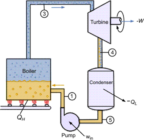
Figure 9: Rankine cycle [7]
The considerations affecting the feasibility of using the Rankine cycle include technicality, cost and practicability. From a technical point of view, the Rankine cycle is quite sound and is being employed in power stations all-round the globe. The landed and available mature technology and professional experience guarantee its steady operation and maintenance. In terms of the costs, initial expense for constructing Rankine cycle power plant can be quite high, so for new designs, constructing a supercritical power plant. But again, the ‘time cost’, ‘capital cost’ among other costs are usually compensated by longer lasting gains such as high efficiency and less fuel consumption.
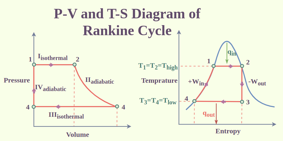
Figure 10: Rankine cycle performance diagram [24]
As far as resources are concerned, Rankine cycle needs water and fuel continuously; a usual fuel being coal, natural gas or nuclear fuel. These resources and the backbone in which these resources move in and are managed in are very vital for the proper implementation of the Rankine cycle. Moreover, modern advancements have contributed to the evolution of micro-Rankine cycle systems as compared to conventional systems, which in turn has helped to increase their application potential in decentralized and renewable energy sources like biomass and geothermal applications [24].
Another concern that could be attributed to the Rankine cycle is the environmental aspect as regards the current drive for cutting down on greenhouse gas emissions and combating climate change. Rankine cycle power plants that dominantly comprise traditional fossil based power plants and especially those based on coal are noteworthy for their exhausting levels of Carbon dioxide emissions that fuel the prospects of global warming. Sometime, other pollutants are also emitted through burning which include sulfur dioxide and nitrogen oxides that lead to acid rain and respiratory diseases, respectively.
Thus, there has been a transition to the cleaner sources of energy such as natural gas and nuclear energy as applied to Rankine cycle power plants. Additionally, the application of carbon capture and storage (CCS) as a part of the utilized Rankine cycle will considerably decrease the level of carbon emissions originating from fossil-fueled power plants. In addition, the formulation of fresh resource kinds for generating electricity, including biomass and geothermal energy source, help to increase the ecological benefits of the Rankine cycle. These resources in generating energy are characterized as emitting less pollution and utilizing sustainable resources hence following the global set environmental standards [25].
2.5. Electric turbochargers
Having delved into the Rankine cycle as a highly efficient technology for converting thermal energy into mechanical energy and then into electrical energy, we next turn our attention to another form of energy recovery and enhancement that is becoming increasingly important in modern automotive technology - the electric turbocharger.
A turbocharger is a unit comprising a turbine mounted on a shared shaft. It functions as a pneumatic device, powered by the exhaust gases from the engine, to generate mechanical energy. The compressor, driven by the turbine's energy, serves as a pneumatic machine that draws in clean air and elevates its pressure [26]. Electric turbocharger, i.e., electronic turbocharger is based on the traditional turbocharger with the addition of an electronic control device, more commonly used in small-displacement turbocharged engines. Figure 11 is used to illustrates the system layout of the electric turbocharger. It comprises a radial compressor and a turbine, interconnected via a shaft, which also houses the permanent magnet of the electric motor. The upstream humidified fuel cell stack and the downstream water separator constitute the air path downstream of the compressor [27]. Electric turbochargers utilise electrical energy to directly drive the turbine, thus avoiding the problem of sluggish response of traditional turbochargers at low engine speeds. When the motor is activated, the turbine rotates rapidly, compressing the air entering the engine and increasing the intake pressure and density, which in turn increases the engine's combustion efficiency and power output. An electric turbocharger is usually directly connected to the intake system of the engine. The motor receives signals through the control unit to adjust the speed and power output to the needs of the engine. In some cases, such as in hybrid vehicles or vehicles equipped with energy recovery systems, the electric turbocharger can also be involved in the energy recovery process. The battery is recharged by recovering braking energy when the vehicle is slowing down or braking. When the battery is fully charged, this stored energy can be used to drive the electric turbocharger and other electric auxiliary equipment when the vehicle accelerates, thus reducing fuel consumption.
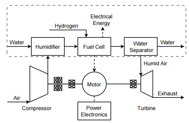
Figure 11: Structure of the electric turbocharger embedded in the fuel cell system [27]
A good transient response can significantly enhance the drivability of a vehicle. The conventional internal combustion engine (ICE) operates with the aid of a turbocharging system, which increases volumetric efficiency (referring to the engine's ability to draw in and use more air per cylinder stroke) to a certain degree. However, one of its drawbacks is its inability to execute a swift transient response, which refers to the engine's capacity to rapidly adjust its power output in response to changes in throttle position or load, ensuring a smooth and responsive driving experience. The study by Dimitriou(2017) [8] found that electric turbochargers rapidly increase turbine speed by reducing turbine size and utilising electrically-assisted technology, and that the responsiveness of the turbocharger is significantly improved, while maintaining a certain level of energy recovery efficiency. Figure 12 summarizes the layout of the ideal engine resulting from the above research.
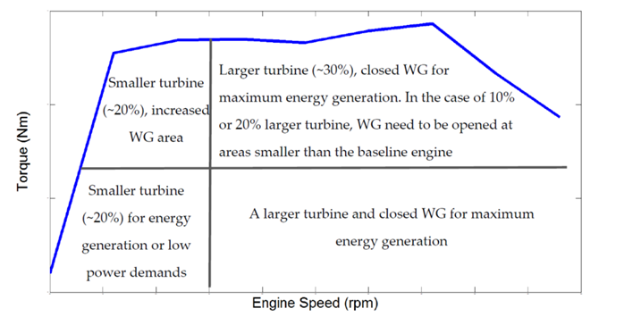
Figure 12: Ideal component sizing for maximum power and energy harvesting [8]
The electric turbocharging system maximises peak torque, fast response time and energy recovery over a range of speeds and loads under real driving conditions. W.Wagino(2024) [9] has shown that the use of electric turbochargers is effective in reducing fuel consumption, extending driving range, and reducing carbon monoxide and hydrocarbons in tailpipe emissions. Figure 13 demonstrates the comparison of fuel consumption with and without the electric turbocharger in action. This discovery has important implications for improving vehicle drivability, fuel economy and environmental performance. Although electric turbocharging technology faces challenges such as complex integration and control, high cost and high requirements for batteries and charging facilities, its potential high efficiency and environmental benefits should not be overlooked. It is expected to become an important direction in the development of the internal combustion engine as the technology advances and costs are reduced.
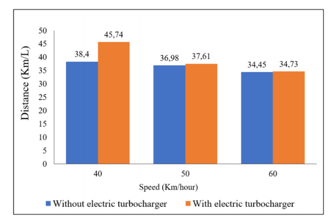
Figure 13: Fuel assessment comparison [9]
The challenge lies in developing a cost-effective and environmentally friendly powertrain for city cars that can effectively recover energy to enhance efficiency and reduce emissions. Pure electric vehicles, although they do not emit emissions, face challenges in terms of range and in terms of charging infrastructure.R.Capata [28] proposed in his study that a mild hybrid powertrain capable of having all the waste energy utilised by a turbine to generate electrical energy that can be delivered to the battery pack. The design concept of this system is to mechanically separate the compressor and turbine unit, powering the compressor with a dedicated electric motor and performing additional work through the turbine generator. The benefit lies in the fact that, within contemporary supercharger systems, the excess energy at both lower and higher operating ranges is released through the waste-gate valve, bypassing the turbine expansion process. On the other hand, mild hybrid systems aim to bridge the gap between conventional and fully electric vehicles. Table 2 illustrates the innovative turbocharger configuration used in this system[28].This turbocharger allows energy recovery through a mechanically separated but electrically coupled compressor and turbine, enabling the system to utilise energy during deceleration and braking.
Table 2: The modified turbine operating points [28]
ICE rpm | m [ kg/s] | Turbine rpm | βc | Tin [K] | Tout [K] | P[W] | η |
2000 | 0.024 | 82,170 | 1.2 | 954 | 922 | 780 | 0.87 |
3500 | 0.04 | 134,483 | 1.6 | 1005 | 930 | 3510 | 0.86 |
5500 | 0.07 | 164,002 | 2 | 1045 | 932 | 9500 | 0.81 |
The results indicate that the novel turbocharger design is capable of effectively recovering energy during deceleration and braking, thereby improving the overall efficiency of the mild hybrid power train. Compared to pure electric vehicles, the mild hybrid system offers the potential for reduced emissions while maintaining acceptable range and performance, with potential advantages in terms of feasibility, cost-effectiveness and environmental benefits.R. Capata [10] et al. verified the feasibility of a road prototype of a hybrid propulsion vehicle powertrain by studying and implementing an innovative supercharger applied to a 900 ml internal combustion engine of a city car.From the analysis of the data, it was possible to confirm the correspondence with the existing turbocharger models installed in the reference vehicle, where Figure 14 shows the actual operating point of the compressor. It is argued that, while pure electric vehicles represent the ultimate goal for zero-emission transportation, mild hybrid systems can provide a practical intermediate solution that leverages existing technologies and infrastructure to facilitate the transition towards a more sustainable transportation sector.
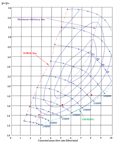
Figure 14: Operative radial compressor map and actual operating points in function of ICE rpms [10]
3. Conclusion
This paper presents a comprehensive examination of modern technologies for automobile energy recovery, focusing on practical and implementable advancements. Energy recovery is anticipated to play a significant role in the future of automobile technology due to its potential for improving fuel efficiency and reducing emissions. This study explored various energy recovery systems (ERS) including regenerative braking, thermoelectric generators, electric turbochargers, flywheel energy storage systems, and the Rankine cycle, providing insights into their advantages and challenges.
• Electric turbocharger significantly improves the transient response of the engine and effectively reduces the hysteresis commonly associated with conventional turbochargers. Electric turbocharger also quickly adapts to changes in engine conditions to provide a smoother and more responsive acceleration experience. Hybrid electric turbochargers can already be integrated into automobiles and achieve significant fuel savings and waste heat recovery benefits.
• Flywheel energy storage systems (FESS) use advanced materials and efficient technologies to improve energy efficiency and speed of operation, showing significant advantages in grid stability and renewable energy integration. Facing the challenges of market acceptance and regulatory standards, flywheel energy storage systems need to optimize energy density further and reduce energy storage losses to promote the commercialization process.
• The Rankine cycle remains one of the most essential and constantly used technologies in power generation and is referred to as an efficient heat-to-electricity conversion method. Parallel to a new direction in fuel use, the Rankine Cycle will remain relevant in the future due to its link with renewable energy technologies and technological improvements.
• Regenerative braking systems play a crucial role in enhancing the efficiency and sustainability of electric vehicles by converting a portion of the kinetic energy into usable electrical energy. It is a vital technology in transitioning towards more efficient and sustainable transportation.
• Thermoelectric generators are one of the technologies that need more time to refine. But if one can be finished, the energy recycle will be better used in automobiles. The key problem that needs to be solved will be heat energy reserve and better material to improve the energy conversion efficiency.
Electric turbo is the energy recovery system we recommend that more researchers investigate and research. Because it is one of the technologies over the last decade, it is widely used not only on road cars but also in the world of motorsport.
References
[1]. V. Rakov, “Determination of optimal characteristics of braking energy recovery system in vehicles operating in urban conditions,” Transp. Res. Procedia, vol. 50, pp. 566–573, 2020, doi: 10.1016/j.trpro.2020.10.068.
[2]. C. Armenta-Déu and H. Cortés, “Analysis of Kinetic Energy Recovery Systems in Electric Vehicles,” Vehicles, vol. 5, no. 2, pp. 387–403, Mar. 2023, doi: 10.3390/vehicles5020022.
[3]. Y. Yang, Q. He, Y. Chen, and C. Fu, “Efficiency Optimization and Control Strategy of Regenerative Braking System with Dual Motor,” Energies, vol. 13, no. 3, p. 711, Feb. 2020, doi: 10.3390/en13030711.
[4]. A. G. Olabi, T. Wilberforce, M. A. Abdelkareem, and M. Ramadan, “Critical Review of Flywheel Energy Storage System,” Energies, vol. 14, no. 8, Art. no. 8, Jan. 2021, doi: 10.3390/en14082159.
[5]. K. Xu, Y. Guo, G. Lei, and J. Zhu, “A Review of Flywheel Energy Storage System Technologies,” Energies, vol. 16, no. 18, Art. no. 18, Jan. 2023, doi: 10.3390/en16186462.
[6]. Y. Zhao, S. Wang, M. Ge, Z. Liang, Y. Liang, and Y. Li, “Performance analysis of automobile exhaust thermoelectric generator system with media fluid,” Energy Convers. Manag., vol. 171, pp. 427–437, Sep. 2018, doi: 10.1016/j.enconman.2018.06.006.
[7]. F. Zhou, S. N. Joshi, R. Rhote-Vaney, and E. M. Dede, “A review and future application of Rankine Cycle to passenger vehicles for waste heat recovery,” Renew. Sustain. Energy Rev., vol. 75, pp. 1008–1021, Aug. 2017, doi: 10.1016/j.rser.2016.11.080.
[8]. P. Dimitriou, R. Burke, Q. Zhang, C. Copeland, and H. Stoffels, “Electric Turbocharging for Energy Regeneration and Increased Efficiency at Real Driving Conditions,” Appl. Sci., vol. 7, no. 4, p. 350, Apr. 2017, doi: 10.3390/app7040350.
[9]. W. Wagino et al., “Implementation of an Electric Turbocharger on A Single-Cylinder Spark Ignition Engine in an Effort to Use Ethanol Gasoline E40,” TEM J., pp. 161–166, Feb. 2024, doi: 10.18421/TEM131-16.
[10]. R. Capata, “Experimental Fitting of Redesign Electrified Turbocompressor of a Novel Mild Hybrid Power Train for a City Car,” Energies, vol. 14, no. 20, p. 6516, Oct. 2021, doi: 10.3390/en14206516.
[11]. S. J. Clegg, “A Review of Regenerative Braking Systems.” White Rose Research Online. [Online]. Available: https://eprints.whiterose.ac.uk/2118/1/ITS105_WP471_uploadable.pdf.
[12]. N. Huda, S. Kaleg, A. Hapid, M. R. Kurnia, and A. C. Budiman, “The influence of the regenerative braking on the overall energy consumption of a converted electric vehicle,” SN Appl. Sci., vol. 2, no. 4, p. 606, Apr. 2020, doi: 10.1007/s42452-020-2390-3.
[13]. “Energies | Free Full-Text | A Review of Flywheel Energy Storage System Technologies.” Accessed: Jun. 20, 2024. [Online]. Available: https://www.mdpi.com/1996-1073/16/18/6462
[14]. “Applied Sciences | Free Full-Text | A Review of Flywheel Energy Storage System Technologies and Their Applications.” Accessed: Jun. 20, 2024. [Online]. Available: https://www.mdpi.com/2076-3417/7/3/286
[15]. “Review of flywheel based energy storage systems | IEEE Conference Publication | IEEE Xplore.” Accessed: Jun. 27, 2024. [Online]. Available: https://ieeexplore.ieee.org/document/6036455
[16]. X. Yan, S. Nie, B. Chen, F. Yin, H. Ji, and Z. Ma, “Strategies to improve the energy efficiency of hydraulic power unit with flywheel energy storage system,” J. Energy Storage, vol. 59, p. 106515, Mar. 2023, doi: 10.1016/j.est.2022.106515.
[17]. “Sustainability | Free Full-Text | Feasibility Assessment of a Small-Scale Agrivoltaics-Based Desalination Plant with Flywheel Energy Storage—case Study: Namibia.” Accessed: Jun. 20, 2024. [Online]. Available: https://www.mdpi.com/2071-1050/16/9/3685
[18]. “Energies | Free Full-Text | Design and Sizing of Electric Bus Flash Charger Based on a Flywheel Energy Storage System: A Case Study.” Accessed: Jun. 20, 2024. [Online]. Available: https://www.mdpi.com/1996-1073/15/21/8032
[19]. K. Yazawa and A. Shakouri, “Fuel-burning thermoelectric generators for the future of electric vehicles,” Energy Convers. Manag., vol. 227, p. 113523, Jan. 2021, doi: 10.1016/j.enconman.2020.113523.
[20]. X. Lu, X. Yu, Z. Qu, Q. Wang, and T. Ma, “Experimental investigation on thermoelectric generator with non-uniform hot-side heat exchanger for waste heat recovery,” Energy Convers. Manag., vol. 150, pp. 403–414, Oct. 2017, doi: 10.1016/j.enconman.2017.08.030.
[21]. D. Kim et al., “Design and performance analyses of thermoelectric coolers and power generators for automobiles,” Sustain. Energy Technol. Assess., vol. 51, p. 101955, Jun. 2022, doi: 10.1016/j.seta.2022.101955.
[22]. S. Lan, R. Stobart, and R. Chen, “Performance comparison of a thermoelectric generator applied in conventional vehicles and extended-range electric vehicles,” Energy Convers. Manag., vol. 266, p. 115791, Aug. 2022, doi: 10.1016/j.enconman.2022.115791.
[23]. A. Domingues, H. Santos, and M. Costa, “Analysis of vehicle exhaust waste heat recovery potential using a Rankine cycle,” Energy, vol. 49, pp. 71–85, Jan. 2013, doi: 10.1016/j.energy.2012.11.001.
[24]. X. Yu, Z. Li, Y. Lu, R. Huang, and A. P. Roskilly, “Investigation of organic Rankine cycle integrated with double latent thermal energy storage for engine waste heat recovery,” Energy, vol. 170, pp. 1098–1112, Mar. 2019, doi: 10.1016/j.energy.2018.12.196.
[25]. T. A. Horst, W. Tegethoff, P. Eilts, and J. Koehler, “Prediction of dynamic Rankine Cycle waste heat recovery performance and fuel saving potential in passenger car applications considering interactions with vehicles’ energy management,” Energy Convers. Manag., vol. 78, pp. 438–451, Feb. 2014, doi: 10.1016/j.enconman.2013.10.074.
[26]. C. C. Suciu, S. V. Igret, I. Vetres, and I. Ionel, “Review of the Integration of Hybrid Electric Turbochargers for Mass-Produced Road Vehicles,” Energies, vol. 17, no. 6, p. 1484, Mar. 2024, doi: 10.3390/en17061484.
[27]. S. Lück, T. Wittmann, J. Göing, C. Bode, and J. Friedrichs, “Impact of Condensation on the System Performance of a Fuel Cell Turbocharger,” Machines, vol. 10, no. 1, p. 59, Jan. 2022, doi: 10.3390/machines10010059.
[28]. R. Capata and E. Sciubba, “Study, Development and Prototyping of a Novel Mild Hybrid Power Train for a City Car: Design of the Turbocharger,” Appl. Sci., vol. 11, no. 1, p. 234, Dec. 2020, doi: 10.3390/app11010234.
Cite this article
Li,S.;Xu,P.;Cheng,H.;Tao,J.;Feng,Y. (2025). Pathways to Enhance Vehicle Efficiency and Sustainability with Energy Recovery Technology. Theoretical and Natural Science,107,58-73.
Data availability
The datasets used and/or analyzed during the current study will be available from the authors upon reasonable request.
Disclaimer/Publisher's Note
The statements, opinions and data contained in all publications are solely those of the individual author(s) and contributor(s) and not of EWA Publishing and/or the editor(s). EWA Publishing and/or the editor(s) disclaim responsibility for any injury to people or property resulting from any ideas, methods, instructions or products referred to in the content.
About volume
Volume title: Proceedings of the 4th International Conference on Computing Innovation and Applied Physics
© 2024 by the author(s). Licensee EWA Publishing, Oxford, UK. This article is an open access article distributed under the terms and
conditions of the Creative Commons Attribution (CC BY) license. Authors who
publish this series agree to the following terms:
1. Authors retain copyright and grant the series right of first publication with the work simultaneously licensed under a Creative Commons
Attribution License that allows others to share the work with an acknowledgment of the work's authorship and initial publication in this
series.
2. Authors are able to enter into separate, additional contractual arrangements for the non-exclusive distribution of the series's published
version of the work (e.g., post it to an institutional repository or publish it in a book), with an acknowledgment of its initial
publication in this series.
3. Authors are permitted and encouraged to post their work online (e.g., in institutional repositories or on their website) prior to and
during the submission process, as it can lead to productive exchanges, as well as earlier and greater citation of published work (See
Open access policy for details).
References
[1]. V. Rakov, “Determination of optimal characteristics of braking energy recovery system in vehicles operating in urban conditions,” Transp. Res. Procedia, vol. 50, pp. 566–573, 2020, doi: 10.1016/j.trpro.2020.10.068.
[2]. C. Armenta-Déu and H. Cortés, “Analysis of Kinetic Energy Recovery Systems in Electric Vehicles,” Vehicles, vol. 5, no. 2, pp. 387–403, Mar. 2023, doi: 10.3390/vehicles5020022.
[3]. Y. Yang, Q. He, Y. Chen, and C. Fu, “Efficiency Optimization and Control Strategy of Regenerative Braking System with Dual Motor,” Energies, vol. 13, no. 3, p. 711, Feb. 2020, doi: 10.3390/en13030711.
[4]. A. G. Olabi, T. Wilberforce, M. A. Abdelkareem, and M. Ramadan, “Critical Review of Flywheel Energy Storage System,” Energies, vol. 14, no. 8, Art. no. 8, Jan. 2021, doi: 10.3390/en14082159.
[5]. K. Xu, Y. Guo, G. Lei, and J. Zhu, “A Review of Flywheel Energy Storage System Technologies,” Energies, vol. 16, no. 18, Art. no. 18, Jan. 2023, doi: 10.3390/en16186462.
[6]. Y. Zhao, S. Wang, M. Ge, Z. Liang, Y. Liang, and Y. Li, “Performance analysis of automobile exhaust thermoelectric generator system with media fluid,” Energy Convers. Manag., vol. 171, pp. 427–437, Sep. 2018, doi: 10.1016/j.enconman.2018.06.006.
[7]. F. Zhou, S. N. Joshi, R. Rhote-Vaney, and E. M. Dede, “A review and future application of Rankine Cycle to passenger vehicles for waste heat recovery,” Renew. Sustain. Energy Rev., vol. 75, pp. 1008–1021, Aug. 2017, doi: 10.1016/j.rser.2016.11.080.
[8]. P. Dimitriou, R. Burke, Q. Zhang, C. Copeland, and H. Stoffels, “Electric Turbocharging for Energy Regeneration and Increased Efficiency at Real Driving Conditions,” Appl. Sci., vol. 7, no. 4, p. 350, Apr. 2017, doi: 10.3390/app7040350.
[9]. W. Wagino et al., “Implementation of an Electric Turbocharger on A Single-Cylinder Spark Ignition Engine in an Effort to Use Ethanol Gasoline E40,” TEM J., pp. 161–166, Feb. 2024, doi: 10.18421/TEM131-16.
[10]. R. Capata, “Experimental Fitting of Redesign Electrified Turbocompressor of a Novel Mild Hybrid Power Train for a City Car,” Energies, vol. 14, no. 20, p. 6516, Oct. 2021, doi: 10.3390/en14206516.
[11]. S. J. Clegg, “A Review of Regenerative Braking Systems.” White Rose Research Online. [Online]. Available: https://eprints.whiterose.ac.uk/2118/1/ITS105_WP471_uploadable.pdf.
[12]. N. Huda, S. Kaleg, A. Hapid, M. R. Kurnia, and A. C. Budiman, “The influence of the regenerative braking on the overall energy consumption of a converted electric vehicle,” SN Appl. Sci., vol. 2, no. 4, p. 606, Apr. 2020, doi: 10.1007/s42452-020-2390-3.
[13]. “Energies | Free Full-Text | A Review of Flywheel Energy Storage System Technologies.” Accessed: Jun. 20, 2024. [Online]. Available: https://www.mdpi.com/1996-1073/16/18/6462
[14]. “Applied Sciences | Free Full-Text | A Review of Flywheel Energy Storage System Technologies and Their Applications.” Accessed: Jun. 20, 2024. [Online]. Available: https://www.mdpi.com/2076-3417/7/3/286
[15]. “Review of flywheel based energy storage systems | IEEE Conference Publication | IEEE Xplore.” Accessed: Jun. 27, 2024. [Online]. Available: https://ieeexplore.ieee.org/document/6036455
[16]. X. Yan, S. Nie, B. Chen, F. Yin, H. Ji, and Z. Ma, “Strategies to improve the energy efficiency of hydraulic power unit with flywheel energy storage system,” J. Energy Storage, vol. 59, p. 106515, Mar. 2023, doi: 10.1016/j.est.2022.106515.
[17]. “Sustainability | Free Full-Text | Feasibility Assessment of a Small-Scale Agrivoltaics-Based Desalination Plant with Flywheel Energy Storage—case Study: Namibia.” Accessed: Jun. 20, 2024. [Online]. Available: https://www.mdpi.com/2071-1050/16/9/3685
[18]. “Energies | Free Full-Text | Design and Sizing of Electric Bus Flash Charger Based on a Flywheel Energy Storage System: A Case Study.” Accessed: Jun. 20, 2024. [Online]. Available: https://www.mdpi.com/1996-1073/15/21/8032
[19]. K. Yazawa and A. Shakouri, “Fuel-burning thermoelectric generators for the future of electric vehicles,” Energy Convers. Manag., vol. 227, p. 113523, Jan. 2021, doi: 10.1016/j.enconman.2020.113523.
[20]. X. Lu, X. Yu, Z. Qu, Q. Wang, and T. Ma, “Experimental investigation on thermoelectric generator with non-uniform hot-side heat exchanger for waste heat recovery,” Energy Convers. Manag., vol. 150, pp. 403–414, Oct. 2017, doi: 10.1016/j.enconman.2017.08.030.
[21]. D. Kim et al., “Design and performance analyses of thermoelectric coolers and power generators for automobiles,” Sustain. Energy Technol. Assess., vol. 51, p. 101955, Jun. 2022, doi: 10.1016/j.seta.2022.101955.
[22]. S. Lan, R. Stobart, and R. Chen, “Performance comparison of a thermoelectric generator applied in conventional vehicles and extended-range electric vehicles,” Energy Convers. Manag., vol. 266, p. 115791, Aug. 2022, doi: 10.1016/j.enconman.2022.115791.
[23]. A. Domingues, H. Santos, and M. Costa, “Analysis of vehicle exhaust waste heat recovery potential using a Rankine cycle,” Energy, vol. 49, pp. 71–85, Jan. 2013, doi: 10.1016/j.energy.2012.11.001.
[24]. X. Yu, Z. Li, Y. Lu, R. Huang, and A. P. Roskilly, “Investigation of organic Rankine cycle integrated with double latent thermal energy storage for engine waste heat recovery,” Energy, vol. 170, pp. 1098–1112, Mar. 2019, doi: 10.1016/j.energy.2018.12.196.
[25]. T. A. Horst, W. Tegethoff, P. Eilts, and J. Koehler, “Prediction of dynamic Rankine Cycle waste heat recovery performance and fuel saving potential in passenger car applications considering interactions with vehicles’ energy management,” Energy Convers. Manag., vol. 78, pp. 438–451, Feb. 2014, doi: 10.1016/j.enconman.2013.10.074.
[26]. C. C. Suciu, S. V. Igret, I. Vetres, and I. Ionel, “Review of the Integration of Hybrid Electric Turbochargers for Mass-Produced Road Vehicles,” Energies, vol. 17, no. 6, p. 1484, Mar. 2024, doi: 10.3390/en17061484.
[27]. S. Lück, T. Wittmann, J. Göing, C. Bode, and J. Friedrichs, “Impact of Condensation on the System Performance of a Fuel Cell Turbocharger,” Machines, vol. 10, no. 1, p. 59, Jan. 2022, doi: 10.3390/machines10010059.
[28]. R. Capata and E. Sciubba, “Study, Development and Prototyping of a Novel Mild Hybrid Power Train for a City Car: Design of the Turbocharger,” Appl. Sci., vol. 11, no. 1, p. 234, Dec. 2020, doi: 10.3390/app11010234.