


1. Introduction
In the contemporary era, vehicle energy recovery technology has become a top priority. This is not only crucial for addressing emission issues to alleviate air pollution but also plays a significant role in energy conservation, aiming to maximize benefits. The relationship between automobiles and thermal energy recovery systems is closely intertwined. By utilizing technologies such as regenerative braking systems, fuel cell thermal energy recovery systems, and exhaust heat recovery systems, it is possible to effectively enhance energy utilization efficiency, reduce energy waste, and mitigate the negative environmental impacts. The research is energy recovery about regenerative breaking, mechanical flywheel, thermoelectric and electric turbochargers. This research will explore these four subtopics from two criteria: energy recovery efficiency and feasibility.
Energy recovery efficiency is various methods and systems designed to recover and reutilize energy lost during energy conversion or usage processes. These technologies aim to enhance overall energy utilization efficiency, reduce energy waste, and minimize environmental impact. Exhaust gas turbochargers (EGTs), the forerunner in waste heat recovery technology, can be operated economically and reduce fuel consumption and CO2 emissions. Combining mechanical energy storage systems with flywheel kinetic energy recovery system (KERS) technology can improve energy conversion efficiency. The Regenerative Braking Utility Quantity Concept can be used in the process of increasing the efficiency of energy recovery during regenerative braking while improving driving smoothness and safety. In order to reduce interference with the thermoelectric generator (TE) and battery, we discusses an automobile thermoelectric waste heat energy recovery system that uses a Cúk converter for power conditioning, the system additionally uses MPPT control. And it successfully boost the power production by up to 14.5% and 22.6%, respectively. Q. Tang et al. to enhance the energy utilization efficiency of internal combustion engines, a numerical simulation testing coupling method was employed to investigate the application of an electronically controlled turbocharger (ECT) for waste heat energy recovery in IC engines. The results indicated that within the effective operating range, both the recovery efficiency of the ECT and the utilization efficiency of waste gas energy increased with rising load and speed, achieving maximum values of 8.4% and 18.4%, respectively. Boretti's experiments were designed to explore a compact car engine and vehicle model based on a flywheel kinetic energy recovery system and to assess its fuel economy and greenhouse gas emissions through simulation tests. The system is capable of converting kinetic energy generated during driving into electrical energy for storage and releasing it to provide power when needed, thereby improving fuel efficiency and reducing greenhouse gas emissions. J. Huh et al. made a concept called regenerative breaking practical quantity to solve the problem of decelerate linearity when using regenerative braking in HEV. They optimized the regenerative braking strategy by building a simulation model to monitor the health of each vehicle system. As a result, the regenerative braking energy recovery efficiency is increased by 28%. G. Shu et al, use TEG systems in internal combustion engines combination of segmented and traditional TEMs and a fin-equipped heat exchanger maximum output power of 89.7 W.
Feasibility is the ability to evaluate the applicability, economic viability, and performance of specific components or materials in the context of automotive design and manufacturing processes. Downsized spark ignition engines have a larger throttle opening than conventional internal combustion engines, which reduces the associated pumping losses, and improves feasibility. A novel power-split flywheel hybrid powertrain (PS-FHV) is a viable system with higher fuel economy and faster acceleration than conventional hybrid electric vehicles (HEVs), making it more feasible. The implementation of the novel control strategy significantly improves the performance of the regenerative braking system under safety-critical conditions and has the potential to increase the feasibility and effectiveness of the regenerative braking system. The paper also mentioned the feasibility of replacing the traditional internal combustion engine with a thermoelectric generator in automotive powertrains, highlighting the performance in extended-range electric vehicles. R. Bontempo et.al. They enhanced their prior experimental configuration, enabling more precise transient assessments on both the chilled and heated side branches of the test subjects. Although steady-state performance charts for the turbocharger can be easily acquired through the semi-automated testing protocol, but a thorough examination of unsteady phenomena cannot be predicted, such as the emergence of mild and severe compressor surge incidents, but this is the key to safe operation. The experiments of Song et al. present the design and performance evaluation of a novel power-split flywheel hybrid vehicle (PS-FHV). The article presents a novel PS-FHV design using only one drivetrain to provide full hybrid functionality at any speed for improved fuel economy and acceleration. They modeled and analyzed the system using the leverage principle and simulated the driving of the PS-FHV to assess the feasibility of the system and estimate its performance. The results show that the PS-FHV is a viable system and offers similar fuel economy and better acceleration compared to hybrid-electric vehicles with considerable feasibility. C. Qiu et al. proposes the concept of serial control strategy, which integrates a dynamic adjustment mechanism that optimally balances regenerative braking force with traditional friction braking, to enhance overall vehicle stability and safety. Control experiments were carried out under different road conditions, and the results showed that the new regenerative braking strategy could improve braking safety and comfort. W. Bou Nader feasibility of replacing the traditional internal combustion engine with a thermoelectric generator in automotive powertrains, Subsequent simulations revealed that the TEG's fuel economy would surpass that of the ICE if the system's efficiency could be raised to 39% (achieved with a benefit factor of ten and a heat recovery efficiency of ninety-two percent). In this instance, the TEG would use 7.7% less gasoline in both configurations than the ICE.
This paper will compare the performance of regenerative breaking, mechanical flywheel, thermoelectric and electric turbochargers under different circumstances. This study analyzes the energy recovery efficiency and expected availability of four automotive components.
Research Question: What is the impact on total energy recovery efficiency and vehicle performance in various automobile types of integrating regenerative brakes, electric turbochargers, mechanical flywheels, and thermoelectric generators?
Research Hypothesis: Regenerative brakes, electric turbochargers, mechanical flywheels, and thermoelectric generators, these four mechanical components can effectively improve the energy recovery efficiency of vehicles and have a certain impact on vehicle performance.
2. Discussion
2.1. Electric turbocharger
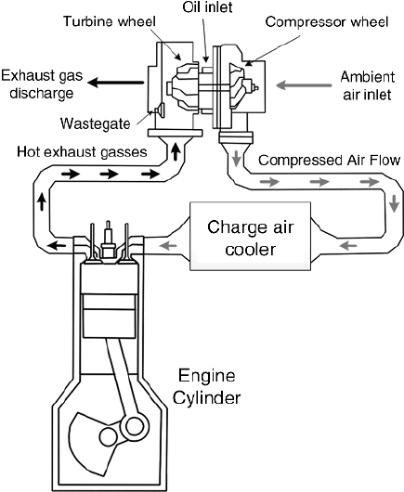
Figure 1: A schematic of a turbocharging system [2]
By compressing the air, a turbocharger is a kind of air compressor that raises the intake air volume [1]. A turbocharger consists of two primary components: a turbine and a compressor [1]. The compressor draws in air from the surrounding environment and compresses it, increasing its density through the rotating impeller blades [1]. This high-density airflow then enters the engine's combustion chamber, where it mixes with fuel and the increased air density results in a higher mass flow rate, which boosts brake mean effective pressure exerted on the piston crown [1]. Consequently, this increases the force acting on the piston, allowing the engine to generate more torque and, in turn, more power [1]. Electric turbochargers can provide instantaneous power enhancement and conserve energy by shutting down autonomously [2]. As seen in Fig 1, it clearly shows us how the turbocharger works, which can help us better understand the description above.
2.1.1. Energy recovery efficiency
While the ECT idea has been around for a while and is a useful technique to improve engine performance, there is not much research done on the energy of exhaust gas for the ECT system, especially on gasoline engines [3]. Thus, more research is still needed to develop the applicability of the ECT system of engine WHR [3].
The ECT was investigated from the point of view of the exhaust gas energy utilization for the engine rather than the turbocharger performance, the turbocharger plays a secondary role in this case, as well as the energy conservation benefits of ECT as a method of engine WHR were analyzed through test and simulation [3].
This paper takes the turbocharged engine with exhaust gas turbocharging as the research subject [3]. Prior to the numerical investigation of the ECT (Exhaust Gas Turbocharging), to develop the simulation model and for its calibration, bench tests were carried out on the tar engine at the AVL dyno at different speeds as well as different load conditions [3]. Speed variation was maintained at 200 r/min while the load variation was maintained at 1 bar BMEP (Brake Mean Effective Pressure). Among the parameters which were registered, were engine rotational speed, torque, air and fuel mass flow rates, as well as intake and exhaust pressures and temperatures at various operating modes of the engine [3]. Shown in Fig. 2 is schematic diagram of the engine test bench which indicates the location of different testing equipment [3]. The GT-Power model schematic for exhaust turbocharged gasoline engines is displayed in Fig. 3 [3]. This diagram illustrates the various sub-components of the GT-Power model, including cylinders, intake and exhaust manifolds, compressors, turbines, intake and exhaust valves, etc. Generally, the boundary conditions determine how accurate and efficient the GT-Power model is. This study uses experimentation and measurement to identify the target engine's construction specifications [3].
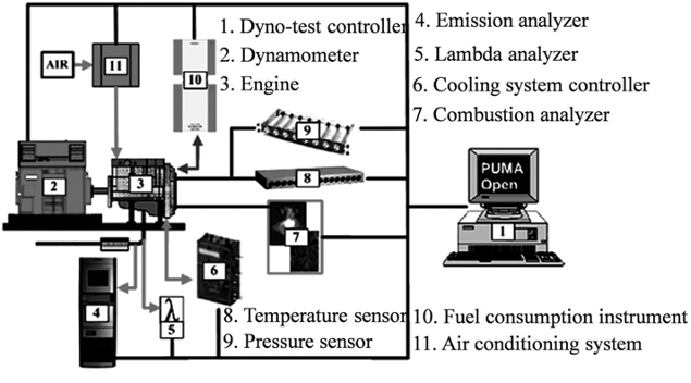
Figure 2: The schematic diagram for engine bench testing [3]
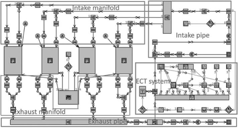
Figure 3: The GT-Power model of exhaust gas turbocharged engine
The main results are shown in Figs.4 (a)–4 (f). From these figures, it can be observed that as the wastegate equivalent diameter decreases, the ECT output power increases and the engine power reduces with the total output power of the engine being constant [3]. The compressor outlet pressure does not change while the turbine inlet pressure keeps on increasing. Therefore, the engine PMEP increases with the reduction of wastegate equivalent diameter as described in [3]. Fig. 4(e) represents the percentage of improvement in ECT engine thermal efficiency and Fig. 4(f) represents the brake efficiency of ECT engine. From the above comparison, it can be observed that the effect of ECT is higher than that of PMEP so the overall result is an increase in the effective thermal efficiency of the engine [3]. The findings reveal that if the equivalent diameter of the bypass valve is less than 11mm and the expansion ratio of the turbine is more than 2.4, it is impossible to further reduce the size of the bypass valve for the turbine [3]. Regarding the braking efficiency of the two types of engines: In the range of 2000 r/min to 5000 r/min the total braking efficiency of the ECT engine is higher than that of the EGT engine; at the same time when the speed is below 2000 r/min or above 5000 r/min the efficiency of ECT engine is nearly the same as of EGT engine [3]. This can be particularly observed in Figs 5 which makes it easier for the reader to comprehend the above-mentioned content. The throttle regulates the gasoline engine's load, and when the angle of attack is more than thirty degrees, the engine's power and overall output power only minimally fluctuate with the angle of attack. It has been noted that when the throttle angle increases, the compressor outlet pressure decreases but the turbine inlet pressure stays constant [3].
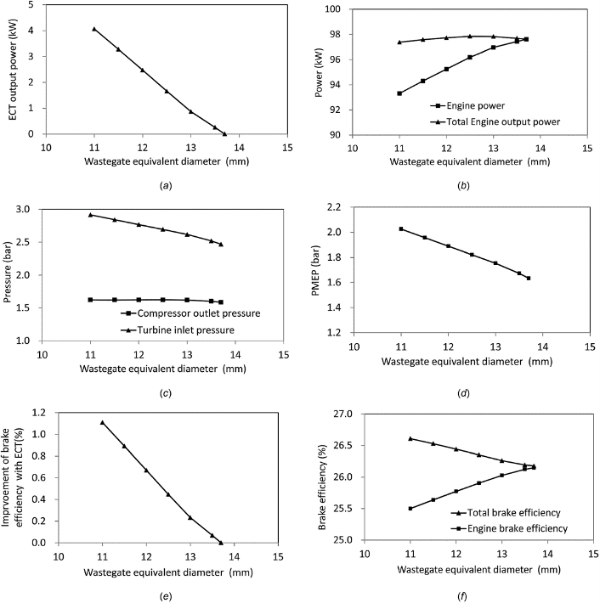
Figure 4: Simulation results for an ECT engine operating at 5000 rpm under full load conditions: (a) ECT output power, (b) engine power output, (c) system pressure, (d) engine PMEP (Pumping Mean Effective Pressure), (e) enhancement of ECT engine efficiency, and (f) ECT engine braking efficiency [3]
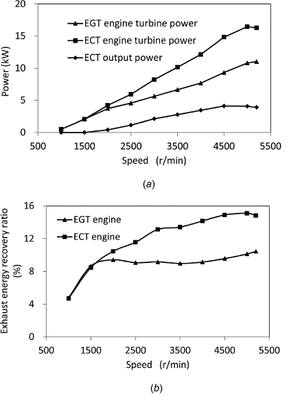
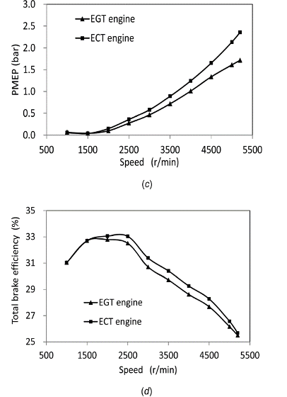
Figure 5: The harnessed power from the ECT system: (a) generated power, (b) efficiency of exhaust gas utilization, (c) PMEP , and (d) braking efficiency of the ECT [3]
The numerical results of the present study are presented in Figs.6(a)–6(f). This can be observed in Fig. 6(a), and as the throttle angle rises the ECT output power rises as well under this condition [3]. More specifically, the ECT output power augmentation will increase with decreasing throttle angle. The overall engine output power and engine power do not change considerably if the throttle angle is increased when it is larger than 30 degrees [3]. The compressor outlet pressure and the turbine intake pressure are shown in Fig. 6(c) [3]. The compressor outlet pressure is found to reduce as the throttle angle is increased while the turbine inlet pressure remains almost constant [3]. This is due to the fact that, even when the overall engine power remains constant, a portion of the turbine power is utilized to power the motor, which causes the target or necessary engine power to decrease [3]. As a result, the necessary compressor outlet pressure (engine intake gas pressure) is lowered [3]. Additionally, as shown in Fig. 6(d) [3], the PMEP of the ECT engine decreases with the throttle angle. Nevertheless, the pressure at the compressor outlet or the necessary intake pressure decreases as the throttle angle increases. But as the throttle angle increases, the ECT power and engine thermal efficiency both improve. As seen in Figs.6(e) and 6(f), the greatest improvement in engine brake efficiency is 0.7% points [3]. There are two main causes for this. When the throttle is opened, the engine PMEP decreases and the motor receives its effective power from the turbine [3]. The combined effect of the two types raises engine thermal efficiency [3].
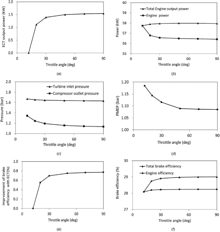
Figure 6: The power recovered by the ECT under partial load conditions: (a) ECT power output, (b) engine power, (c) system pressure, (d) PMEP , (e) enhancement of braking efficiency, and (f) engine braking efficiency [3]
As can be seen from the above analysis, the existing GT-Power is capable of reproducing the ECT engine but, owing to the constraints of the initial turbocharger, most of the engine operating points are shifted from the turbocharger map before the engine’s bypass valve is fully open [3]. This is because it does not effectively capture the effect of Exhaust Gas Temperature (ECT) [3]. The effect of ECT cannot be seen and well defined because the wastegate is opened [3]. On the basis of this, a larger turbocharger can be matched with the engine such that all engine operation points are located within the range of the turbocharger map [3]. This change will lead to less pumping losses and an improved thermal efficiency of the engine [3].
The ECT approach was analyzed through engine bench tests, and numerical simulation concerning the WHR was considered. Based on the above discussion the following conclusions can be made. However, by using the ECT system, Although the ECT engine's overall thermal efficiency is improved, the engine pumping losses are increased. The highest improvement in brake efficiency is 2.3%. Because of the increase in exhaust gas mass flow rate, the energy of the exhaust gas absorbed by ECT increases as the by-pass valve opening is decreased [3]. When the by-pass valve opening reaches a particular level, the engine operation points are beyond the turbine map due to the lack of flexibility in the original engine turbocharger map [3]. The energy recovery efficiency of the ECT and the energy utilization efficiency of the exhaust gas under high speed and high load conditions both improved when the larger turbocharger was reused; their maximum values were 8.4% and 18.4%, respectively [3]. Thus, under the specified circumstances, the engine's thermal efficiency might be increased by roughly 5.0% [3]. Moreover, powering the compressor through ETC could improve engine performance at low speeds [3]. Accordingly, in the ECT system, the compressor runs on the remaining energy that the turbine extracts from the exhaust gas, with the remaining energy being utilized to generate the effective work of the ECT [3]. Under high-speed and high-load operating conditions, the efficiency of energy recovery from the exhaust gas by ECT is greater than 8.0%, indicating the considerable energy-saving advantage of ECT over alternative WHR techniques [3].
2.1.2. Feasible
The advantages of using turbochargers in ICE are evident and the downsizing strategy includes the improvement of brake-specific fuel consumption (BSFC) and emissions. To gain these advantages, it is required to have a proper matching thus very precise maps of operation for both compressor and turbine are crucial [4]. However, turbocharger manufacturers often provide their customers with limited information and low reliability, for example, it is frequently the case that information regarding pulsing flow conditions at the turbine intake or compressor instabilities (rotating stall and surge) is lacking [4]. The impact of the turbocharger speed is sometimes mentioned in a single line with no information regarding the turbine operating parameters, and detailed efficiency data are infrequent [5]. On occasion, turbine data has been collected in cold and continuous flow rigs with flow characteristics that differ greatly from the real conditions [5]. In the author's previous article [4], the experimental setup was not adequately designed to analyze the performance of turbochargers [4]. In this paper, we propose a drilling rig configuration that incorporates several improvements in the layout of the experimental setup, which are presented and discussed within the measurement chain [5]. Specifically, the actual configuration of the experimental setup allows for a more accurate analysis of three relevant aspects of turbocharger performance [5].
As illustrated in Fig 7, the experimental setup consists of four subsystems: the Data Acquisition and Control Unit (DCU), the Testing Section (TS), the Cold Gas Generator (CGG), and the Hot Gas Generator (HGG) [5]. The latter relies on a 2.5-liter diesel engine with direct injection [5]. To maintain the quality of exhaust energy in terms of temperature and pressure, the internal combustion engine (ICE) has been modified by removing its turbocharger [5]. Following the removal of the turbocharger, the associated power deficiency has been addressed by utilizing the CGG system, as depicted in Fig 7, to restore the boost to the ICE [5].
The experiment was conducted using the established experimental setup [5]. The testing was carried out on a small automatic power turbocharger with an engine having a power and displacement of 50-130 HP and 0.4-1.2 L and a maximum rated speed of 200 rpm [5]. The ICE has been deprived of its turbocharger to maintain the quality of the exhaust gases, as well as their temperature and pressure. The power loss resulting from the removal of the turbocharger has been compensated by using the CGG system as depicted in Fig 7 to supercharge the ICE. Specifically, the cold gas supply is secured by an ATLAS Copco GA55VSD two-stage intercooler screw compressor with a power of 55 kW at the full load. A high-performance regulator valve with an integrated PID control system that is home-made is used to control the engine boost pressure. The compressed air storage is done in a 2000-liter tank that has a maximum pressure of 12 bar. Furthermore, the CGG has the ability to track the original engine's boost pressure map, which has been determined through a series of prior testing. Lastly, a Borghi and Safari eddy current dynamometer absorbs the mechanical power generated by the ICE to permit both steady and unsteady state operation.
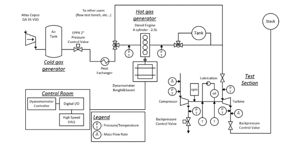
Figure 7: Schematic view of the rig [4]
Steady state results: The typical maps of the compressor and turbine. By operating the rig in accordance with traditional practice, that is, gathering a set of flow rate pressure ratio data points (g, π) for certain hot gas properties, one can acquire the steady compressor and turbine performance maps [4].
\( {\dot{m}_{corr}}=\dot{m}\sqrt[]{T_{s}^{0}/{T_{ref}}/(p_{s}^{0}/{p_{ref}})} \) , \( {n_{corr}}=n\sqrt[]{T_{s}^{0}/{T_{ref}}} \) In this classic representation, all data across different rotational speed scales, along with the quadratic approximation indicated by the solid line, exhibit a good fit for measurements, with a deterrent coefficient of approximately 0.96 [4]. The suction to delivery static pressure ratio is plotted against the corrected mass flow rate for a range of turbo adjusted rpm values in Figure 8. The corresponding figure, Fig. 9, shows the corrected mass flow rate for various turbocharger corrected rpm values as a function of the static to static turbine expansion ratio [5].
The turbine reaches the choked flow condition at the maximum rotational speed when the pressure ratio is around 2.5 [5].
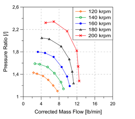
Figure 8: Compressor performance map [4]
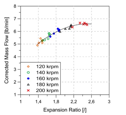
Figure 9: Turbine performance map [4]
Unsteady results: deep and mild surge. The unsteady-state results of a turbocharger refer to the instantaneous performance variations that occur during its operation due to various factors, such as load changes, fluctuations in intake airflow, and temperature variations. These changes can be categorized into deep surges and mild surges.
Two different unstable flow states were investigated, corresponding to the occurrence of mild surging (MS) and deep surging (DS) phenomena [5].MS and DS represents the degree of vibration. Under pre-surge conditions at a rated speed of 130 krpm, transitioning from MS to DS resulted in an approximately 20% reduction in the time-averaged flow velocity, while the root mean square of the mass flow rate significantly increased by about 1200% [5]. Similarly, the pressure signals on the transfer flow surface exhibited substantial differences, particularly in terms of the root mean square of the fluctuations [5]. Furthermore, the quasi-periodic behavior of DS was notably distinct from the non-periodic MS, with considerable variations in the shape of the traces [5].
Due to the high flexibility of HGG, the entire range of operational envelopes for the test items has been obtained [5]. HGG is capable of providing waste heat flow rates influenced by a wide range of temperatures and pressures for turbines [5]. The integration of energy-saving principles applicable to compressors, turbines, bearing housings, and overall turbochargers indicates that the performance of the test items is significantly impacted by the thermal power transfer to the lubricating oil and the surrounding environment [5]. About 20–30% of the compressor's total enthalpy change per unit of time can be found in the algebraic sum of the two thermal powers indicated above [5]. This also implies that the assessment of both factors is largely affected by errors in the assumptions regarding work transfer and efficiency under high flow conditions [5]. Specifically, when assessing compressor efficiency, utilizing classical expressions based on the adiabatic assumption might easily result in a relative inaccuracy of 5–10% [5]. Lastly, the high-frequency pressure and flow rate changes that are generally recorded during unstable events, like pressure surge characteristics, can also be recorded with this drilling apparatus [5]. Compared to pressure variations, there is a greater increase in mass flow rate fluctuations from mild to severe spikes [5]. These results elucidate the effects of small turbochargers under both steady-state and transient conditions, which have implications for the driving stability of compact sedans [5]. Therefore, the operating conditions of such small turbochargers must be considered in this context [5].
This research uses an advanced test bench to investigate the steady and unsteady performance characteristics of a tiny turbocharger for automotive applications [5]. The new rig configuration enables semi-automated and accurate mapping of both the compressor and turbine [5]. It highlights the significant impact of thermal power transfer to lubricating oil and the environment on performance, with thermal losses accounting for 20-30% of the compressor's total enthalpy change [5]. This results in a 5-10% relative error in compressor efficiency calculations based on adiabatic assumptions [5]. Additionally, the apparatus records high-frequency variations in pressure and flow rate linked to compressor surges, demonstrating that as the severity of the surge increases, mass flow rate fluctuations rise more than pressure fluctuations [5].
2.2. Flywheel energy storage system
A flywheel is a rotating mechanical device, which is used to store kinetic energy. The shape of the flywheel is disk-like, as shown in Figure 10. It serves as a reservoir, absorbing mechanical energy, and then storing energy when the supply of energy is more than the requirement and releasing it when the energy requirement is more than the supply.[6] Flywheel efficiency is defined by the maximum energy it can store relative to its weight. A heavier flywheel can accommodate more energy. Additionally, as the flywheel's rotational speed or angular velocity increases, the amount of stored energy also rises. The FESS, also known as Flywheel Energy Storage System, is an energy storage system whose basic principle is to store electrical energy by rotating a flywheel. When the stored energy needs to be released, the flywheel will slow down and generate electricity, a process that can be realized by an electric motor. [7] In the automobile manufacturing industry, FESS and flywheel are commonly used to achieve the goal of energy recovery and enhance the fuel efficiency. It is commonly used in automobile manufacturing industry.
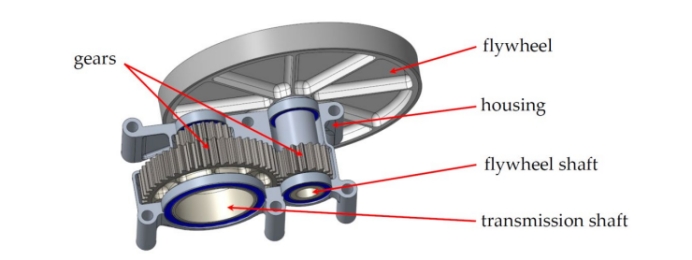
Figure 10: Flywheel and gearbox [7]
2.2.1. Energy recovery efficiency
Conventionally, electric vehicles use batteries to store energy, but this method is costly, bulky, and slow to recharge. We have to develop a new way to upgrade the energy recovery efficiency. In the experiments conducted by Diego-Ayala et al. they tested the performance of a mechanical energy storage system at different speeds while simulating the driving state of a vehicle. In addition, a computer simulation of a full-size vehicle was analyzed to demonstrate the feasibility and superiority of the system. During the experiment, the authors built a physical model and connected it to an air resistance dynamometer to simulate the vehicle's driving condition. The performance parameters and efficiency of the system were derived by analyzing the experimental data at different speeds. [8]
We can also apply the flywheel kinetic energy recovery systems (KERS) to enhance energy efficiency in HEVs. KERS is a technology that converts the kinetic energy generated when a vehicle brakes into electrical energy that can be stored and released to provide auxiliary power during driving. In Boretti's experiments, a simulation analysis based on engine and vehicle models was performed, first defining a test cycle with four NEDC test cycles with different driving modes.[9] Then, an engine and vehicle model was built and simulated using WAVE and Lotus Vehicle Software, and fuel consumption and CO2 emissions were calculated for different operating conditions. By comparing the differences between the KERS-equipped and non-KERS-equipped models, we can conclude the effectiveness of KERS in improving fuel economy and reducing CO2 emissions. [9] In the experiment, the data were collected by collecting the acceleration and braking energy recovery of the vehicle at different speeds. The experiment recorded the driving distance, time, average speed and maximum speed of the vehicle at different speeds, and calculated the energy consumption of the vehicle under different driving conditions based on these data. In addition, the energy recovered by the vehicle while braking is measured and converted into electrical energy stored in the battery for subsequent use. The independent variables in the experiment include the speed of the vehicle, the energy recovery rate during acceleration and braking, etc.; while the dependent variables include the energy consumption of the vehicle under different driving conditions, including the distance travelled, the time, the average speed and the maximum speed. The influence of other factors, such as temperature, humidity, altitude, etc., also needs to be considered. By measuring and analysing these parameters, the performance of different types of powertrains in terms of energy efficiency can be finally assessed.
Table 1: Simulation results and breakdown of energy losses for the conventional, brake-only hybrid and CVT-brake hybrid vehicles [8]
Description | ECE | Artemis-urban | Hyzem-urban | |||||||
Conv. | Brake-only | CVT-brake | Conv. | Brake-only | CVT-brake | Conv. | Brake-only | CVT-brake | ||
Fuel economy (mpg UK) | 31.6 | 33.0 | 35.0 | 28.0 | 31.1 | 35.1 | 30.5 | 33.1 | 34.0 | |
Change in fuel economy over conventional (mpg) | - | 4.2% | 10.7% | - | 11.3% | 25.7% | - | 8.6% | 11.8% | |
Ultimate CO₂ emissions (g/km)² | 235 | 226 | 213 | 266 | 239 | 212 | 244 | 225 | 219 | |
Change in ultimate CO₂ emissions (g/km) | - | -4.0% | -9.7% | - | -10.1% | -20.4% | - | -7.9% | -10.5% | |
% time the engine is OFF | 0% | 12.6% | 22.4% | 0% | 23.9% | 40.1% | 0% | 19.9% | 23.8% | |
Energy Distribution % | ||||||||||
Energy content in Fuel (MJ) | 12.86 | 12.34 | 11.62 | 17.95 | 16.12 | 14.28 | 11.74 | 10.80 | 10.50 | |
Engine losses during propulsion | 71.1% | 72.8% | 73.9% | 69.2% | 70.8% | 70.4% | 71.3% | 73.2% | 72.4% | |
Engine losses during idling | 13.3% | 10.5% | 8.7% | 9.6% | 6.1% | 4.3% | 8.4% | 5.0% | 5.1% | |
Gearbox transmission losses | 3.9% | 4.1% | 4.4% | 4.6% | 4.9% | 6.4% | 4.8% | 5.0% | 5.7% | |
Final drive transmission losses | 0.9% | 1.2% | 1.6% | 1.1% | 1.8% | 2.6% | 1.0% | 1.6% | 2.0% | |
Dissipated by conventional brakes | 5.6% | 1.1% | 0.1% | 10.8% | 2.4% | 0.5% | 9.0% | 1.5% | 0.2% | |
Rolling and aerodynamics losses | 5.2% | 5.7% | 6.0% | 4.7% | 5.4% | 6.1% | 5.4% | 6.1% | 6.3% | |
Dissipated in the ring of the PGS | - | 3.0% | 2.9% | - | 6.2% | 4.4% | - | 5.2% | 4.2% | |
Transmission losses of PGS | - | 0.5% | 0.5% | - | 0.9% | 1.2% | - | 0.8% | 0.7% | |
Aerodynamic and bearing losses in flywheel | - | 0.4% | 0.5% | - | 0.7% | 1.3% | - | 0.5% | 0.7% | |
Remaining in flywheel at end of simulation | - | 0.7% | 1.0% | - | 0.8% | 1.1% | - | 1.0% | 2.1% | |
Losses in CVT branch | - | - | 0.3% | - | - | 1.6% | - | - | 0.5% | |
Based on the data in Table 1, we can know that, firstly, under the urban cycle condition, the hybrid vehicle with mechanical brake has the highest energy recovery efficiency of 34.6%, followed by the hybrid vehicle with CVT brake, with an energy recovery efficiency of 28.2%; while the conventional hybrid vehicle has the lowest energy recovery efficiency of 16.4%.
Throughout the cycle, the hybrid vehicle with mechanical brake has the smallest energy loss, with a total energy loss of only 14.4kWh/km, followed by the hybrid vehicle with CVT brake, with a total energy loss of 17.6kWh/km; while the conventional hybrid vehicle has the largest energy loss, with a total energy loss of 21.6kWh/km. Throughout the cycle, the three types of hybrid vehicles' main energy loss comes from the energy loss of the friction brake, which accounts for 60.3%, 63.2% and 71.4% of the total energy loss, respectively.
By comparing three experimental models; a Conventional Vehicle, a Mechanical Hybrid Vehicle (Brake-only), and a Mechanical Hybrid Vehicle (CVT-brake), it is concluded that flywheel based mechanical hybrid system can effectively store and release energy, reducing fuel consumption and emissions. Advantages of the system include low cost, high reliability, and long life; disadvantages include high weight. Nonetheless, the system has a wide range of applications, especially in situations where rapid acceleration and high speeds are required. Therefore, the system is a promising alternative that deserves further research and development.
Table 2: Computed fuel economies of a compact car with traditional power trains and KERS [9]
Configuration | Fuel [L/100km] | CO₂ [g/km] | Energy [MJ/km] |
1.6L TDI | 3.8 | 99 | 1.38 |
1.6L TDI + KERS | 3.2 | 82 | 1.15 |
1.2L TDI | 3.6 | 95 | 1.33 |
1.2L TDI + KERS | 3.0 | 79 | 1.10 |
Besides, based on the data given in Table 2, it can be seen that the introduction of KERS can significantly augment the fuel economy of compact cars. Without KERS, the 1.6-litre TDI diesel engine consumes 3.16 litres of fuel per 100 kilometres travelled, whereas with KERS this figure drops to 2.85 litres, a reduction of approximately 9.5 per cent. In addition, by further reducing the engine to 1.2 litres and combining it with the torque assist of KERS, fuel consumption can be further reduced to 2.79 litres, a reduction of approximately 12.3 per cent compared to the situation without KERS. The adoption of KERS technology can significantly improve fuel economy and reduce CO2 emissions. Especially for small-displacement diesel engines, the effect of KERS technology is even more obvious. Overall, combining mechanical energy storage systems and KERS technology can improve energy conversion efficiency. Therefore, the system is a promising alternative that deserves further research and development.[9]
2.2.2. Feasibility
Despite the advantages of flywheel energy storage—such as low cost, long lifespan, high energy efficiency, and reliability—flywheel hybrid vehicles (FHV) have yet to be produced on a large scale. This is largely due to their typical use of two kinds of transmissions—one for the engine and another for the flywheel—which raises concerns about cost, packaging, and complexity. However, based on the experiment by Song et al., a new power-split flywheel hybrid powertrain (PS-FHV) that employs only a single transmission can be implemented to alleviate these challenges.[10]
The PS-FHV includes three planetary gear sets and a Continuously Variable Transmission (CVT) integrated into flywheel to fully provide hybrid functionality at any speed, resulting in faster acceleration and higher fuel economy. To validate the operation of the PS-FHV, the system was modeled and analyzed using Leverage Analysis. This approach highlighted the system's capabilities for power distribution and regulation control, which are essential for achieving hybrid driving mode. A simulation of the PS-FHV's driving performance was conducted to evaluate the feasibility and effectiveness of the resulting model.[10]
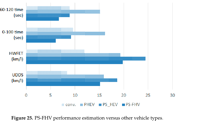
Figure 11: PS-FHV performance estimation versus other vehicle types [10]
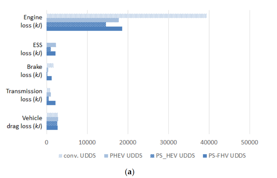
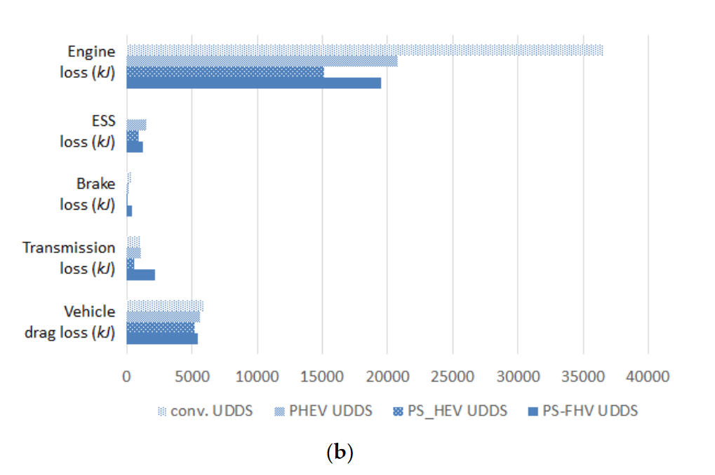
Figure 12: Comparing energy loss between the PS-FHV and other powertrain types; (a) UDDS driving cycle; and (b) HWET driving cycle [10]
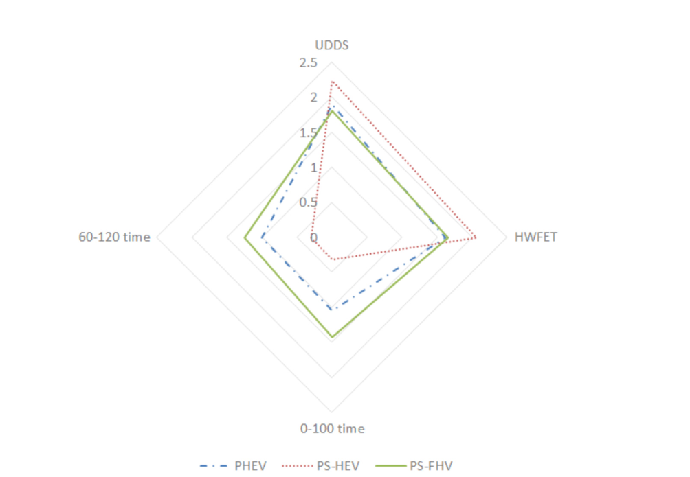
Figure 13: Performance comparison of the proposed flywheel hybrid powertrain with other powertrain types [10]
Based on Figure 11, we can see that the other vehicle types (e.g., PHEV and PS-HEV) perform similarly in terms of acceleration but improve in terms of fuel economy when compared to conventional vehicles. However, the PS-FHV outperforms the other vehicle types in all three aspects, especially in acceleration, where it outperforms the PHEV and PS-HEV.In addition, as can be seen in Figure 12, the mechanical drivetrain of the PS-FHV has more energy losses compared to the battery and flywheel. Finally, from Figure 13, it can be seen that the PS-FHV performs well in terms of fuel economy and power performance in both the HWFET and UDDS driving cycles. In particular, its acceleration performance is excellent. Therefore, all in all, PS-FHV is considered as a better hybrid powertrain solution, which is able to strike a balance between fuel economy and power performance, with very considerable feasibility, and has a great potential for energy recovery systems in the future.
Song et al. modeled and analyzed the PS-FHV to demonstrate its feasibility and evaluate the performance. In the result, it shows that the PS-FHV is a more feasible and better system that offers higher fuel economy and faster acceleration compared to conventional hybrid electric vehicles (HEVs). Therefore, this system can be used as a more effective alternative to advance future hybrid vehicle technology. [10] The flywheel energy storage system has already enhanced the energy recovery efficiency of HEVs, and it is economical and environmentally friendly, compared to traditional vehicles. Applying the use of PS-FHV can further boost fuel economy and facilitate vehicle performance, achieving the goal of high-level energy recovery.
2.3. Regenerative braking
Regenerative braking is a mechanism utilized in vehicles, particularly electric and hybrid cars. In this system kinetic energy that would otherwise be lost as heat during braking is converted into electrical energy and stored for future use. This process involves the reversal of an electric motor's operation to act as a generator, harnessing the vehicle's momentum to charge its batteries as shown in Figure 14. By seamlessly switching from acceleration to regeneration mode, these vehicles improve energy efficiency and reduce overall fuel consumption.
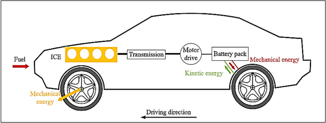
Figure 14: Schematic diagram representing energy flow of a hybrid electric vehicle [11]
2.3.1. Energy recovery efficiency
In modern electric and hybrid vehicles, one of the significant challenges is maximizing energy efficiency. Regenerative braking is a key technology aimed at addressing this issue by recapturing some of the energy typically lost during braking and feeding it back into the vehicle’s battery. However, the efficiency of this process can be limited by various factors such as braking intensity, vehicle speed, and the state of the battery. Inefficient energy recuperation can lead to reduced overall range and increased reliance on the primary power source, whether it be electricity or fuel. Additionally, traditional braking systems that are not optimized for regenerative braking can contribute to suboptimal performance. The problem, therefore, is how to enhance the efficiency of energy recuperation during braking to improve the vehicle’s overall energy usage and performance.
To improve energy recuperation efficiency, The author, Jeewook Huh, came up with the concept called regenerative breaking practical quantity[12]. Regenerative breaking practical quantity solved problem of decelerate linearity. The concept reflects the performance curves of different components, such as electric motors, when braking, It is used for the coordination of on-board computer systems such as HCU (Hydraulic control unit), MCU (Micro control unit), ECU (Electronic control unit), etc[12]. The concept aims to reduce the loss of deceleration linearity during regenerative braking in hybrid vehicles, allowing different systems to work together to reduce internal friction and thus improve energy recuperation efficiency.
The study utilizes both experimental and theoretical approaches to collect data on regenerative braking control for hybrid electric vehicles (HEVs). The study involves practical implementation and testing of the regenerative braking system in real vehicle scenarios, validating the effectiveness of the new control logic and its impact on fuel efficiency and braking performance. The development of the control logic involves simulations or mathematical models to predict the behavior of the regenerative braking system under various conditions. The regenerative breaking practical quantity measures the torque through the AHB, which controls the MCU to shift gears, and finally the HCU brakes based on the shift information, as shown in Figure 15 [12]. This allows the fragmented systems to be brought together and reduces energy losses. Since it is not possible to directly derive the regenerative braking efficiency, the authors developed a method for calculating the regenerative braking utilization rate when shifting gears, Re genAV = Tmotor × GR[12].

Figure 15: Regenerative braking flow[12]
According to the research of J. Huh et al., the HCU calculates the motor charge torque limit from the wheel chargeable power standard for the motor and battery, and the wheel standard calculation for the MCU and BMS. The HCU ultimately calculates the amount of regenerative braking available, taking into account the amount of regenerative braking allowed by EBS [12]. As can be seen in Figure 16, it is the hydraulic brake transition that causes the loss of speed. When the logic of the available regenerative braking amount is applied, the motor torque command remains dashed, and the regenerative braking amount increases even if the transmission loosens the phenomenon. As a result, braking linearity and shift quality can be ensured [12].
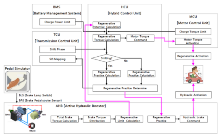
Figure 16: Before/after by battery charge limit logic[12]
Studies have shown that the active regenerative braking strategy reduces fluctuations in deceleration sensation and therefore improves regenerative braking efficiency by 28% and fuel efficiency by 8%[12]. At the same time, its feasibility has also been proven, and it can increase braking stability and improve driving safety. However, this concept is only suitable for hybrid vehicles, not for pure electric vehicles and range extender vehicles, and the application field is limited.
Overall, the Regenerative Breaking Practical Quantity concept can be used as a solution to increase the efficiency of energy recuperation during regenerative braking, while improving driving smoothness and safety. However, its application space is limited, and it is limited to hybrid vehicles rather than pure electric vehicles.
2.3.2. Feasibility
Electric vehicles (EVs) face significant challenges when it comes to safe driving. Regenerative braking restores energy during deceleration and is essential for improving the overall efficiency of the vehicle and extending the driving range. However, traditional regenerative braking strategies often struggle to balance energy recovery with vehicle safety and driving stability, especially in situations that require a quick response, such as emergency braking or high-speed cornering. These conditions can lead to suboptimal performance, such as insufficient energy recovery or compromised vehicle safety. This issue has become even more urgent as the adoption of electric vehicles increases and the demand for efficient, safe and reliable braking systems grows.
In order to solve the limitations of the existing regenerative braking system, the concept of serial control strategy is proposed[13]. The strategy integrates a dynamic adjustment mechanism to achieve an optimal balance between regenerative braking power and traditional friction braking to enhance the overall stability and safety of the vehicle. The proposed solution leverages real-time data inputs, such as vehicle speed, road conditions, and driver input, to dynamically modulate the braking force. This approach is designed to ensure that energy recovery does not come at the expense of vehicle control or passenger safety[13]. In addition, the strategy incorporates advanced predictive control algorithms to predict potential safety risks and proactively adjust braking parameters. This solution maximizes energy recovery while maintaining high safety standards.
The authors conducted extensive road tests to evaluate the performance of their proposed serial control strategy for regenerative braking systems for electric vehicle (EV) in terms of safe driving. The electric vehicle was tested on four types of road conditions: ice, snow, asphalt, and gravel. The initial vehicle speed was set at 50 km/h, and the brake pedal was fully depressed. The experiments compared the proposed serial control strategy with two baseline strategies—non-regenerative control and parallel control.
The non-regen control and the parallel control are compared with the serial control in test on four different types of roads. The test results are listed in Figure 17. Based on the results, it is clear to deduce that the serial control strategy is more favorable than the two baseline strategies in the case of stopping distance and mean deceleration. The stopping distance and mean deceleration on the ice road are 124.74 m and 0.78 m/s2 , severally. The breaking property amelioration of the mean deceleration of the vehicle, have been improved by 4.41% and 14.71% contrasted with non-regen control individually[13].
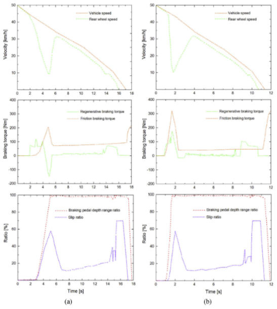
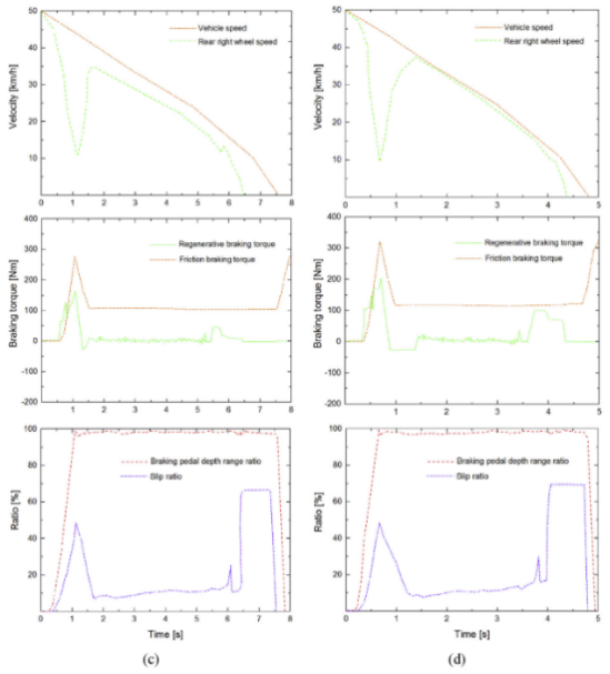
Figure 17: A brake process test results on (a) an ice road, (b) a snow road, (c) asphalt road, (d) a gravel road [13]
The experiments demonstrated that the proposed serial control strategy significantly improved both braking performance and energy recovery in electric vehicles under safety-critical conditions. The results highlighted the effectiveness of the new strategy in enhancing vehicle stability and efficiency compared to traditional control methods. Additionally, the defined parameters for evaluating energy efficiency proved useful in quantifying the benefits of the regenerative braking system.
The paper introduces a new control strategy for regenerative braking in EVs with enhanced feasibility that is quite viable for safety-critical applications. A solution having dynamic adjustments and predictive algorithms, as shown by the proposed solution, recovers energy and keeps the vehicle stable very well. The successful implementation and testing of this strategy demonstrate its potential to improve both the efficiency and safety of regenerative braking systems. Future work should concentrate on optimal adaptation under various driving conditions, long-term performance, and cost-effectiveness. On the whole, this study is useful in advancing knowledge in the field of electric vehicle technologies by providing a feasible solution to one key problem associated with the subject. It does confirm that such innovative solutions will aid electric vehicles as they gain a larger share of our roads.
2.4. Thermoelectric generators
Thermoelectric generators (TEGs) are waste heat recovery devices that, in the absence of an intermediary form, such as steam, in traditional waste heat recovery systems, transform thermal energy directly into electrical energy when a temperature gradient passes through them. The Fig.18 illustrates the mechanism of Thermoelectric generators. [14] This system is based on the Seebeck effect, in which thermal energy is transformed into electrical energy in semiconductors when a temperature gradient produces a voltage potential. [15] Seebeck effect is a thermoelectric phenomenon that produces a voltage differential between two dissimilar materials (semiconductors or semiconductors) that are joined to form junctions and whose junctions are kept at different temperatures, resulting in the formation of a temperature gradient. [14] The kinetic agitation causes electron charge carriers to move in the direction of temperature decrease (from the hot to the cold side), producing electrical potential when the heat is applied to a single junction. When two semiconductors are connected through an electric circuit, a current will be produced. The Fig. 19 demonstrates the process of the Seeback effect. However, compared to other methods such as mechanical flywheels and regenerative braking to increase the efficiency of energy recovery, the poor conversion efficiencies of TEGs, which usually fall between 5% and 10%, make them impractical for use in large-scale energy production.[14]
Figure 18: A schematic representation of a TEG [14]
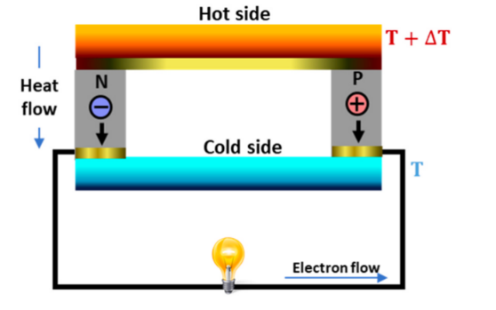
Figure 19: Schematic of a thermoelectric module [14]
2.4.1. Energy recovery efficiency
The efficiency of using energy in gasoline vehicles and hybrid electric vehicles was significantly low because of the waste heat generated by internal combustion engines, especially at the exhaust. [16] The TEG technology can recycle energy waste; However, when the TEG technology generates electricity has a noticeable variation in terminal voltage, particularly during charging, which should not be disregarded. [16] which will decrease the efficiency of generating thermal energy to electric energy. In order to utilize and improve the vehicle performance and reduce fuel consumption. The article mentions a method, which can step up or step down the voltage that efficiently converts the wasted energy from TEGs into usable electrical power. [16]
In order to stabilize and regulate the power output from TEGs, which can convert the waste heat from automotive exhaust into electrical energy, the Cúk converter (depicted in Figure 20 has two switches: 1) switch S realized as a unidirectional first quadrant switch (MOSFET or insulated-gate bipolar transistor and 2) switch D realized as a diode. [16]) was introduced. [15] This may be used in combination with the MPPT control(The maximum power available from a PV array at any one moment is obtained by continuous adjustment of the dc operating point by circuitry connected to utility interactive inverters and certain bigger stand-alone units. This process is known as the MPPT.)[17] to effectively regulate voltage and current to ensure the vehicle's batteries can utilize the maximum amount of power production. [16] This will reduce the strain on the alternator and improve energy efficiency. [16]
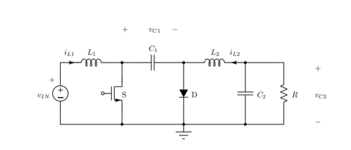
Figure 20: Cuk converter was introduced [16]
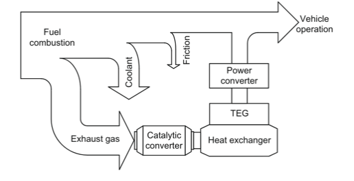
Figure 21: Waste heat energy recovery system [16]
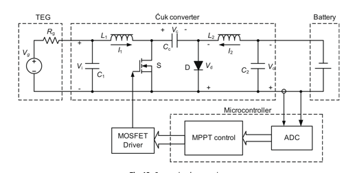
Figure 22: System implementation [16]
In this essay, the thermoelectric modules will be installed at the vehicle's exhaust system. [16] It also uses Cúk converter to stabilize the variable DC voltage to a flat DC voltage level from the TEG to the battery, which means this system ensures the input current and output current are non-pulsating. [16] Secondly, in order to maintain the TEG technology to operate at the highest power output, the MPPT controller will adjust the Cúk converter. [16] Because the TEG technology requires stable temperature environment, the internal combustion engine does not have a rapid vibration of temperature, which provides a suitable environment for TEG technology. [16] The studyincludes a theoretical analysis that predicates the potential power output and efficiency under different operating using calculations. In addition, computer simulations have been used, to optimize the TEG system's design. [16] Finally, the authors create a prototype based on theoretical models to test the performance of the efficiency of converting heat to electricity under a controlled environment. [16] this paper has both theoretical analysis and experimental testing to test the efficiency of converting waste heat to electrical energy using thermoelectric generator (TEG) technology, where the theoretical Analysis includes a theoretical model to foresee the performance of the technology under various operating conditions. By using the computer simulation, it further refined and optimized the TEG system. In the experimental part, it used the theoretical models to construct a prototype TEG system. It uses an electric heater to control the hot side temperature and a water-cooled radiator to stabilize the cold side. This prototype helps them to measure the output voltage, current, and power taken at different load resistances and temperature differences(e.g., 100°C, 150°C, 200°C, 250°C) to validate the theoretical predictions.
The results demonstrate the TEGs can generate electrical power effectively from exhaust whereas the Cúk converter with MPPT control enables the TEG system to work at higher efficiency, which increases from 14.5% to 22.6% from 100 degrees to 250 degrees respectively. [3]
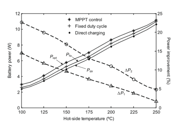
Figure 23: Maximum battery power and power improvement at different temperatures
The experiment uses very accurate equipment and measures four key variables battery voltage, battery current, battery power, and operating temperature. Effects of frequency and power factor are minimized. Table 3 even illustrates the worst-case error scenarios. [3] The maximum reading error occurs at 250 °C which is about ±2.825°C, while the minimum reading error at 50 °C which is = ±1.125°C. As a result, the percentage of power improvement is not much impacted by the temperature measurement mistake. [3] The error analysis emphasizes that even under the worst-case scenarios, the overall power output by using the Maximum Power Point Tracking (MPPT) controller and the Cúk converter, the energy efficiency improvement is significant.
In order to reduce interference with the thermoelectric generator (TE) and battery, this study discusses an automobile thermoelectric waste heat energy recovery system that uses a Cúk converter for power conditioning. [3] This converter provides non-pulsed input and output currents. In order to optimize power transfer utilizing battery voltage and current while accounting for changes in battery voltage during charging and non-constant power losses in the converter, the system additionally uses MPPT control. In comparison to a scheme without MPPT or power regulation, experimental results demonstrate that MPPT may successfully boost the power production by up to 14.5% and 22.6%, respectively. The influence of measurement precision is also explored. [3]
Table 3: Accuracy of measurements
Measurement | Equipment | |
Voltage V | Power analyzer PA2200 | \( ± \) 0.1% (reading) \( ± \) 0.1% (range) \( ± \) 0.01% per kHz 10 mV |
Current I | \( ± \) 0.1% (reading) \( ± \) 0.1% (range) \( ± \) 0.02% per kHz \( ± \) 2 mA | |
Power P | \( ± \) 0.2% (reading) \( ± \) 0.1% (range) \( ± \) 2mW \( ± \) (0.02/PF) % per kHz | |
Temperature T | Thermometer with K-type thermocouple UT327 | \( ± \) 0.85% (reading) \( ± \) 0.7 °C |
Table 4: Impacts of measurement accuracy on power improvement
100℃ | 125℃ | 150℃ | 175℃ | 200℃ | 225℃ | 250℃ | |
\( ∆P \) 1(%) | 14.51 | 11.77 | 9.613 | 7.614 | 5.788 | 3.869 | 1.648 |
\( ∆P \prime \) 1(%) | 10.46 | 8.942 | 7.646 | 6.045 | 4.548 | 2.805 | 0.741 |
\( ∆P \) 2(%) | 22.61 | 19.95 | 16.86 | 13.18 | 10.96 | 7.540 | 4.817 |
\( ∆P \prime \) 2(%) | 18.12 | 16.79 | 14.69 | 11.49 | 9.630 | 6.419 | 3.867 |
Prior research primarily concentrated on the tremendous temperature differential between the axial or radial direction for improving the performance of TEG devices. [19]Relatively limited research has been done on both of these components that interact at the same time. [19]Thus, taking into account the significant temperature gradient in both directions, this work examines the output power enhancement of a TEG system employed for waste heat recovery of a strong diesel engine. [19]The TEG system's essential temperature gradient is matched in its radial direction through the use of the segmented structure of TEMs. [19]While these methods for optimizing heat transfer do an excellent task of improving TEG system performance, they also cause a rise in the back pressure of internal combustion engines. [19] For the reason that to accommodate the substantial temperature gradient along the axial direction, this study uses a variety of thermoelectric materials, each with an ideal temperature range. [19]In order to increase the TEG system's output power, a suitable arrangement of TEMs with two separate structures is investigated. [19]The results will offer direction for enhancing TEG system performance further. [19]
The paper use segmented thermoelectric modules (TEMs) which are 126 thermoelectric couplings electrically coupled in series measuring 56 mm by 56 mm by 5 mm. [19] A pair of p-type and n-type semiconductors coupled by copper, a conductive substance, make up a thermoelectric couple. [19] As seen in Figure 24. (a), the impact of ceramic on the top and bottom sides is thermal isolation to maintain the temperature difference and optimized configurations of heat exchangers. [19] As seen in Figure 25, the thermoelectric generator system under consideration in this study consists of 108 TEMs and a hexagonal heat exchanger. [19] To prevent exhaust gas from flowing along the inner wall of the exhaust channel and increase the hot source temperature of TEMs, there is an air deflector in the middle of the heat exchanger. [19] On the heat exchanger's surface, the TEMs are evenly spaced. Using the heat exchanger's top surface as an example, 18 TEMs are positioned 20 mm apart along the X axis and 9 mm apart along the Z axis. This arrangement will help to increase performance by reducing the disruption of heat transfer between each TEM. [19] As seen in Figure 26, one-sixth of the system is regarded as the computational domain due to the heat exchanger's symmetry. [19]It uses less computing time and maintains the same precision with the integrated TEG system. Compared to the ordinary TEMs system, the TEG system can have a better adaption in large temperature gradients in the radial direction, which leads to a 13.4% increase in maximum output power. [6]Moreover, a multi-TEM configuration that includes both segmented and ordinary modules in the heat exchanger increases the overall performance which is about a 30.8% improvement in output power. [19]Furthermore, integration of extended surfaces in the heat exchanger also be discussed, further improving the power output by about 89.7W, representing a 17.9% improvement.
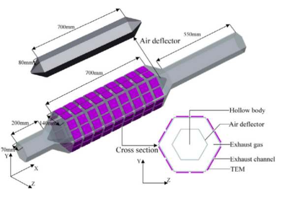
Figure 24: Geometric model of a single thermoelectric element: (a) ordinary structure; (b) segmented structure [19]
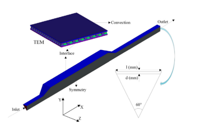
Figure 25: Schematic of the thermoelectric generator system [6]
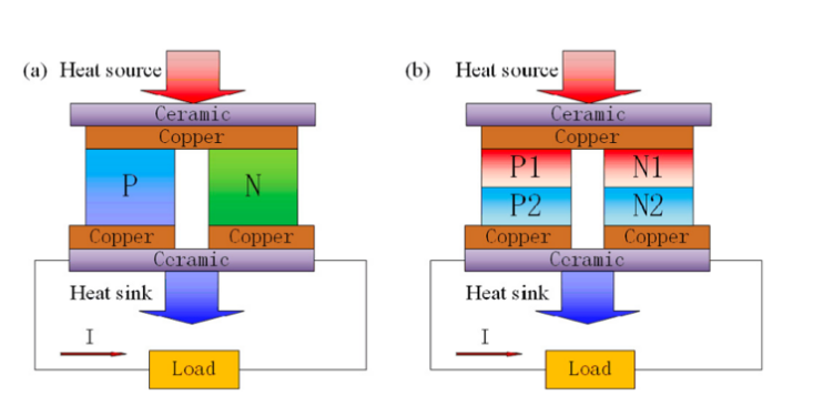
Figure 26: Computational domain (one-sixth of the TEG system) [6]
The paper uses both simulation and experimental approaches. [19]In the simulation part, it uses the FLUENT computational fluid dynamics software which analyzes the effects of varying wall thicknesses and inlet dimensions on the heat exchanger's performance. [19]It also compared the ordinary TEMs and segmented TEMs. [19] It also compared the different load levels under different engine operating conditions. The model was validated using experimental data, demonstrating a relative error of less than 3.8%.[19]
Table 5: Index of TEMs in different simulation cases [19]
Mode types | Mode of single-TEMs | Mode of multi-TEMs | ||||
Structure of TEMs | Case 1 | Case 2 | Case 3 | Case 4 | Case 5 | Case 6 |
Segmented modules ordinary modules | 0 | 1-9 | 1 | 1-3 | 1-5 | 1-7 |
1-9 | 0 | 2-9 | 4-9 | 6-9 | 8-9 | |
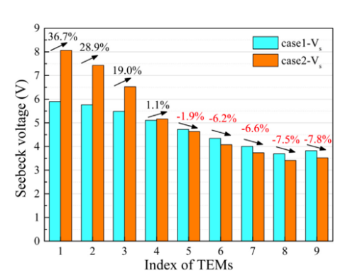
Figure 27: Seebeck voltages of different TEMs in different cases [19]
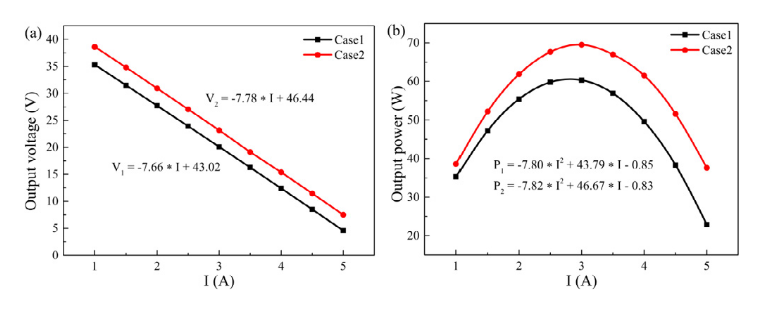
Figure 28: (a) Output voltage and (b) output power with current in different cases [19]
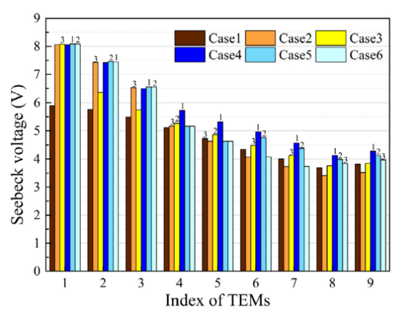
Figure 29: Seebeck voltages of different TEMs in different cases [19]
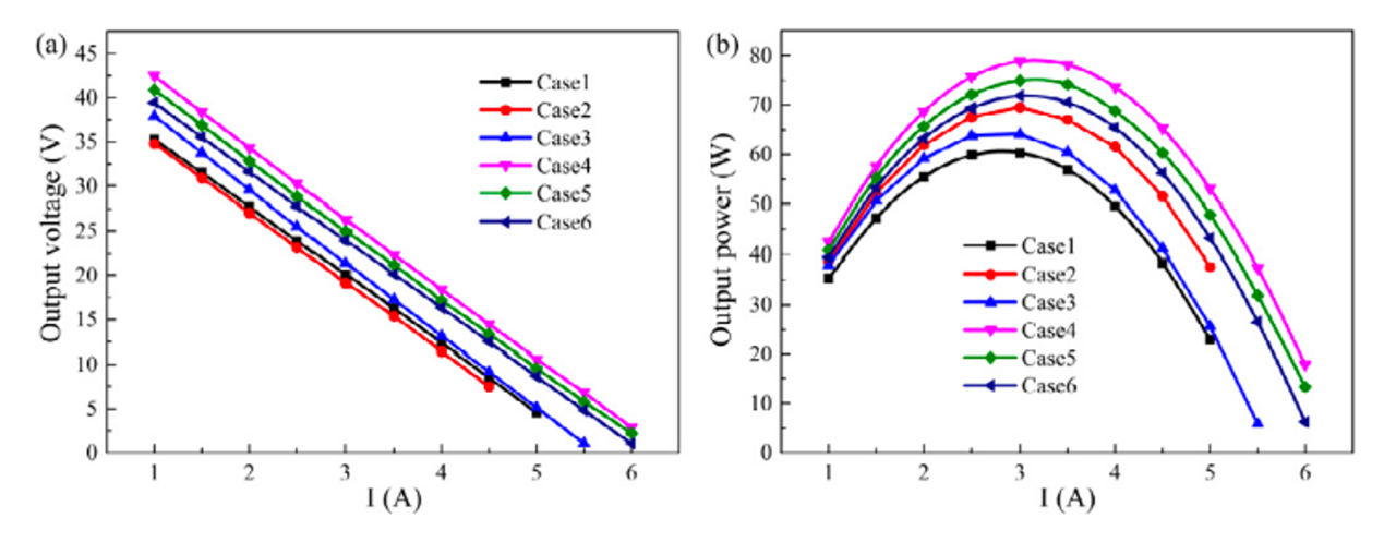
Figure 30: (a) Output voltage and (b) output power with current in different cases [19]
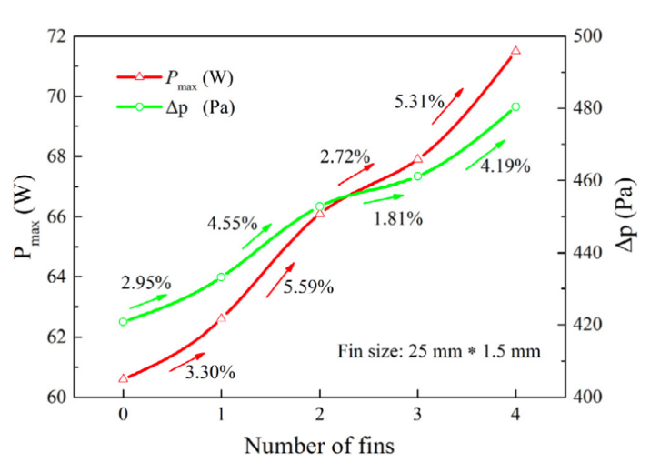
Figure 31: Maximum output power and pressure drop with fins arrangements [19]
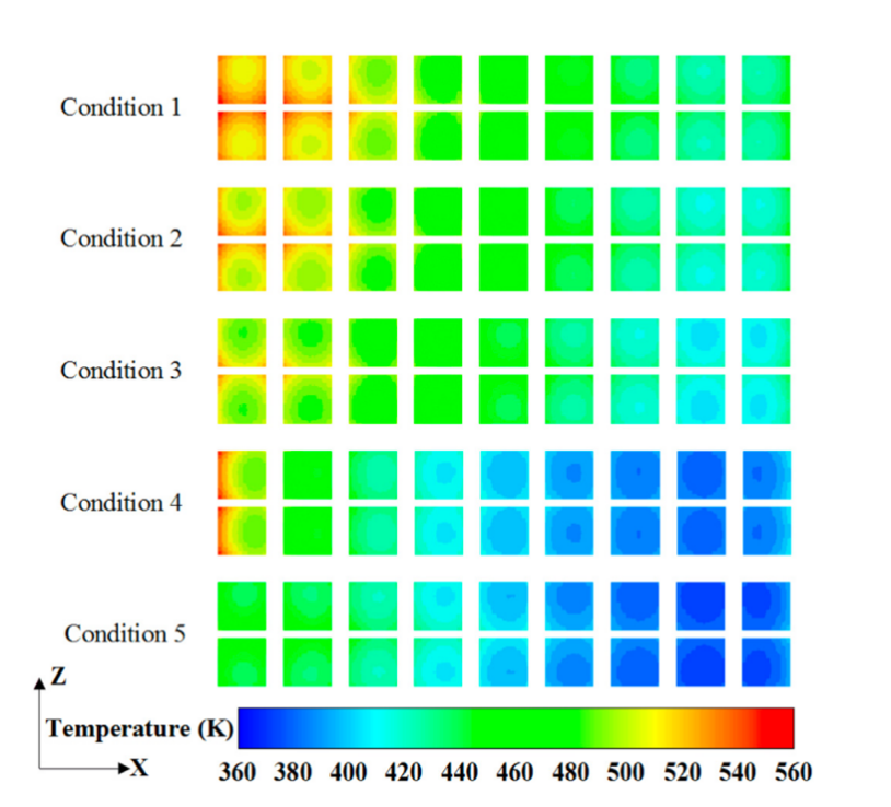
Figure 32: Contours of the hot sides temperature distribution of TEMs for different conditions [19]
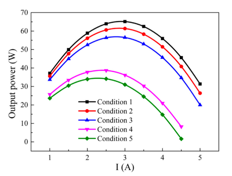
Figure 33: Output power with current in different conditions of the diesel engine [19]
For TEG Configuration the mode for single-TEMs demonstrated a 13.4% increase in maximum output power demonstrated in Figure 29. [19]the temperature difference between the hot and cold sides of TEM was more effectively utilized specifically in the first rows of the heat exchanger. [19]For the multi-TEMs which placed the segmented TEMs in the areas of higher temperature gradients and the traditional TEMs in the areas of lower gradients, the result improved by 30.8% in overall output power, which can be illustrated in Figure 31. [19] In Figure 32. adding more fins in the heat exchanger can increase the maximum output to 17.9% and power to 89.7W. [19]
The result is in Figure 34 demonstrates that when engine power declines, the TEG system's output power also drops. [19]The explanation is that less heat is transferred to the TEMs due to the exhaust gas's decreased mass flow rate and temperature. [19]The outcome demonstrates that when engine power declines, the TEG system's output power also drops. [19]The explanation is that less heat is transferred to the TEMs due to the exhaust gas's decreased mass flow rate and temperature. [19] Using condition 1 to condition 5 in Figure 33, the output power is 83.0 W, 78.9 W, 72.8 W, 56.8 W, and 50.6 W, respectively, when considering condition 3 A. [6]In fact, condition 1 generates more electricity than condition 2, which is ranked lower. [19]The output power of the diesel engine drops by 27.9% and 35.8%, respectively, while it runs at low load conditions 4 and 5, as opposed to condition 2. [19] As a result, the performance of the TEG system is greatly impacted by various diesel engine conditions. [19] Furthermore, the findings show that the TEG system using multiple TEMs is more efficient in recovering waste heat from diesel engines with substantial temperature gradients. [19]
In order to maximize the output power, the heat exchanger needs to decrease the wall thickness and inlet dimensions because of better heat transfer efficiency. [19]However, this may significantly increase the back pressure and may cause a negative effect on engine performance. [6]The paper provides an optimal option which is wall thickness of 3 mm and an inlet cross-section length of 70 mm. [6]
The study concluded that the efficiency of TEG systems in internal combustion engines may be significantly improved by precisely optimizing the combination of segmented and traditional TEMs and a fin-equipped heat exchanger. [6]With a maximum output power of 89.7 W, the best-performing arrangement outperforms traditional designs. [19]
The study illustrates the challenge of enhancing the performance of thermoelectric generators in both conventional vehicles (CV) and extended-range electric vehicles (EEV). [20] The problem is mentioned as how to significantly improve the vehicle's overall efficiency and range by using thermoelectric generators which can convert thermal energy to electrical energy in both types of cars. [20]
Afterward, the vehicle's auxiliary systems, batteries, or even more propulsion to increase range can all be powered by this electricity. [20] Important components of the answer are, firstly, the optimal site: Selecting the EEV's ideal site where the TEG can absorb waste heat the most efficiently. [20]Secondly, selection of Materials: Select some unique materials that work well in the temperature range that electric vehicles typically operate in. [20] Thirdly, integration with vehicle systems: In order to optimize energy recovery without sacrificing vehicle performance, TEGs must be installed in a way that smoothly integrates with the vehicle's current electrical and thermal management systems. [20]
The methodology of the study likely involves both simulation and experimental approaches to assess the performance of TEGs in EEVs and CVs. [7]
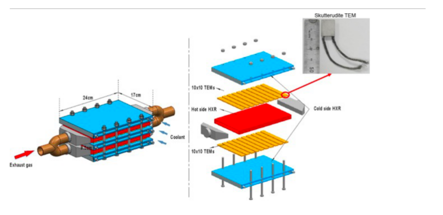
Figure 34: Structure and parameters of the TEG porotype [20]
The researchers prefer to create comprehensive computer models that reproduce the thermal characteristics of electric vehicles (EVs) in a range of driving scenarios. [20] These models are going to take into account things like external temperature, vehicle speed, load, and how well the car's thermal management system is working. [20]
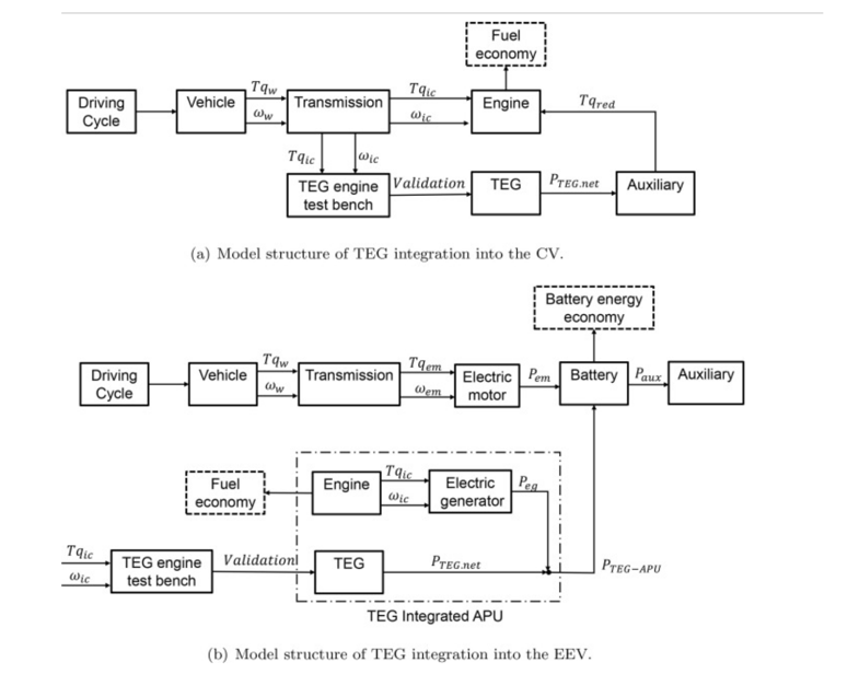
Figure 35: (a)Model structure of TEG integration into the CV (b)model structure of TEG integration into the EEV[20]

Figure 36: TEG engine test bench [20]
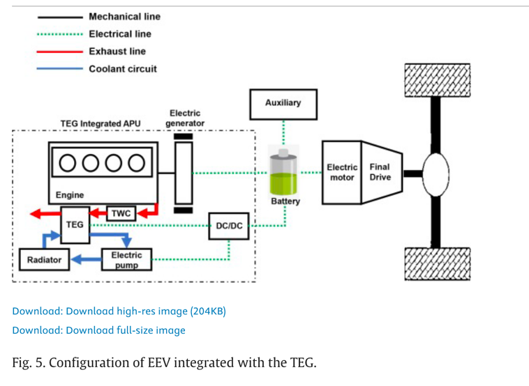
Figure 37: Configuration of CV integrated with the TEG [20]
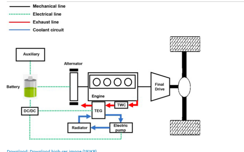
Figure 38: Configuration of EEV integrated with the TEG [20]
In addition to estimating the potential power output of TEGs positioned in various positions within the vehicle, the simulations will also predict the quantity of waste heat produced by various vehicle components. [20]
Additionally, the model will replicate how the electrical energy produced by the TEGs affects the vehicle's overall energy consumption and electric range. [20]
Modified EEVs or prototypes fitted with TEGs will undergo controlled environment testing to gauge the practical performance of TEGs. [7] Driving the car under various situations will be part of the tests to produce real-world data on temperature variations, power production, and efficiency improvements. [7]Researchers will compare the predictions from calculations with experiments to validate the model and enhance our comprehension of TEG performance in EEVs. [7] Moreover, temperature gradients on the TEG, power output (measured in watts), energy conversion efficiency, and the overall effect on the electric range of the EEV are performance metrics that will be important, where the research will also take into account the difficulties in thermal management that come with integrated TEGs, such as the requirement to release surplus heat and maintain the ideal temperature for TEGs and vehicle components. [20]
1. Engine operating
CV-TEG (Conventional Vehicle TEG):
1. A wide range of operating locations, particularly in the low efficiency zone, are available for CV-TEG (Conventional Vehicle TEG). [20]
2. The temperature range of the exhaust is 400–800 K. [20]
3. Because the engine in the CV-TEG drives the car directly, it operates the longest. [20]
EEV-TEG (Electric Enhanced Vehicle TEG):
4. The engine operates more effectively and centrally, using less fuel for the brakes. [20]
5. Depending on the management method, the exhaust temperature is steadier, ranging from 800 K to 1050 K. [20]
6. Compared to CV-TEG, there is an 80% decrease in total operating time and less frequent engine operation. [20]
2. TEG overheating protection strategy
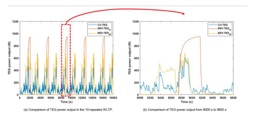
Figure 39: Comparison of TEG power output [20]
CV-TEG:
7. Because exhaust gas temperatures can fluctuate and are frequently high, a bypass technique is needed to avoid overheating. [20]
EEV-TEG:
8. By enabling the TEG to function closer to ideal circumstances, more stable exhaust gas temperatures lessen the requirement for active overheating prevention. [20]
3. Power output of TEG
CV-TEG:
9. Power output is extremely variable and often poor as a result of varying exhaust temperatures and frequent shutdowns. [20]
10. TEG power output is often less than 200 W. [20]
EEV-TEG:
11. Greater and more consistent power production brought about by engine operation's higher exhaust gas temperatures. [20]
12. Compared to CV-TEG, the power output may reach up to 200 W. [20]
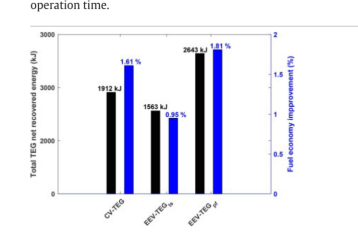
Figure 40: Comparison of total net recovered energy and fuel economy improvement from TEG [7]
4. Increased fuel efficiency
EEV-TEG:
13. Lowers fuel consumption by up to 1.81% while offering greater fuel efficiency benefits. [20]
14. There is a notable increase in the total recovered energy, which enhances overall efficiency. [20]
CV-TEG:
15. Offers even greater fuel efficiency gains, ranging from 1.61% to 3.76%, when traveling at a high, steady pace. [20]
16. The driving cycle and the power needs of the vehicle assistance systems have a significant impact on performance. [20]
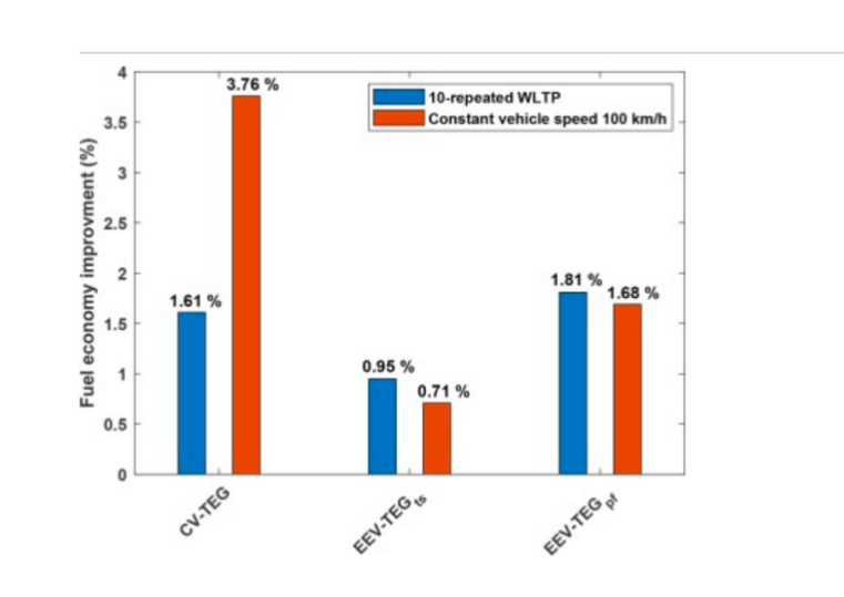
Figure 41: Comparison of fuel economy improvement from TEG in constant vehicle speed 100 km/h [20]
5. Effects of driving circumstances and power management
Power management technique: When compared to the thermostat control method, the EEV-TEG exhibits superior fuel efficiency improvement and gains more from the power follower strategy. [20]
Driving situations: EEV-TEG is more appropriate for driving cycles in cities, whereas CV-TEG works better in continuous highway settings. [20]
6. Auxiliary power demand's impact
CV-TEG: Because less recovered energy is used, fuel efficiency improvement is reduced when auxiliary power demand is lower. [20]
EEV-TEG: Since recovered energy is used directly to the vehicle's propulsion, it is less susceptible to variations in the need for auxiliary power. [20]
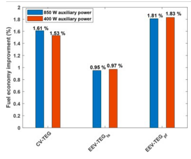
Figure 43: Comparison of fuel saving with different electrical power of the auxiliary in the 10-repeated WLTP [20]
The authors of this paper's conclusion provide a summary of the main conclusions from a comparison of the effectiveness of thermoelectric generators installed in conventional cars vs extended-range electric cars. [7]The main conclusions are briefly categorized as follows:
Highway versus city driving cycle:
In the city driving cycle, TEG helps EEVs with a power follower control technique increase fuel efficiency more than CVs. [7] Conversely, the TEG in the CV outperforms the EEV in terms of fuel savings throughout the highway driving cycle. [20]
Techniques for managing power:
The power management approach has a major impact on TEG performance in EEVs. [20] Thermostatic control is seen to be less appropriate for incorporating TEGs into EEVs than power follower control strategy. [20]
Influence of auxiliary power sources and driving circumstances:
Driving conditions and auxiliary system power demand have an impact on TEG performance in CVs, but not much on TEG performance in EEVs. [7]The study's findings indicate that the incorporation of TEGs into EEVs shows promise, particularly when power follower control techniques are included. [20]
To further increase the energy economy of electric cars, future research should focus on enhancing the power follower control method by figuring out the ideal engine operating point and control thresholds. [20]
It is advised to do hardware-in-the-loop testing to confirm the fuel efficiency of incorporating TEG into EEVs. [20]
In an attempt to reduce carbon emissions from automobiles, the auto industry is investigating low-carbon alternative fuels. [21] However, most of the technology available today is limited to electrified powertrains, especially in range extenders that rely on energy converters, particularly conventional internal combustion engines (ICE). [21] Nevertheless, when used as auxiliary power units (APUs), ICEs have their own efficiency constraints. [21] The potential use of thermoelectric generators (TEGs) as alternative energy converters to improve the fuel economy of hybrid electric vehicles (HEVs) is thoroughly examined in this study. [21]
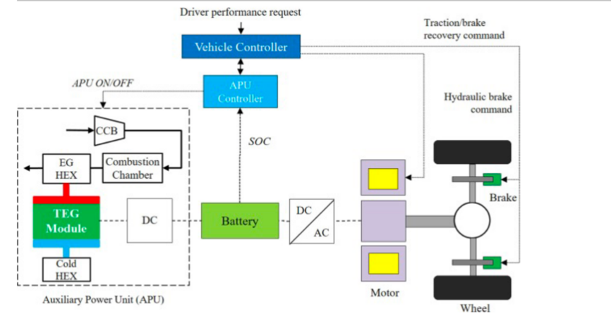
Figure 43: The EREV variant is configured with a basic external combustion TEG-APU [21]
This study is innovative in two respects: first, it is the first to take into account an energy-technological explicit analysis for the purpose of prioritizing and determining which TEG system, out of a range of viable possibilities, is the most efficient to be deployed in an EREV. [21] Secondly, the research offers a comparative evaluation of fuel consumption between ICE-APU and TEG-APU-equipped EREVs with comparable performance. [21]
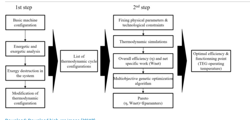
Figure 44: Exergo-technological explicit selection method of the TEG-system for EREV [21]
To acquire the system efficiency, specific work, and energy destroyed, the initial stage was applying energetic and energetic studies to the basic TEG cycle. [21] These factors, along with a focus on the system's exergy destructions, directed the analysis toward determining the various configurations and options that will enable the system to be optimized with regard to exergy losses. [21] These include recuperative processes, multi-thermoelectric stages, combustion chamber reheat, and recuperative processes, among other tenable options. [21] In light of this, a list of possible TEG-system configurations is determined. [21]
Subsequently, all of the energetic and energetic computations are run on all of the configurations that were previously mentioned, determining the technical and physical bounds. [21] As a result, the TEG operating temperature, net-specific work outputs, and matching efficiencies are obtained. Therefore, the optimal trade-off between effort, efficiency, and operating point for the different TEG systems is considered for the EREV application, while taking into consideration realistic physical limits. [21]
The TEG systems operated at their peak efficiency, producing 25 kW of mechanical power. [21] This system enabled a constant speed of 120 km/h without running out of battery power. With a maximum efficiency of 36%, the engine is less efficient than the ICE-APU. Fuel consumption is reduced by 19% for the n2-TEG configuration as compared to the n1-TEG configuration, 25% for the n3-TEG, and up to 31% for the recuperative R-n1-TEG. The RRe-n2-TEG configuration demonstrated the highest efficiency, which resulted in approximately 42% fuel consumption savings compared to the basic n1-TEG. However, the ICE still demonstrated better fuel consumption compared to the performance of the TEG systems. [21] For instance, RRe-n2-TEG operated at 27% efficiency, the ICE had 33% better fuel economy. [21] The eassy also mentioned that increasing the efficiency and merit factors can increasing the competitiveness with ICEs. [21]
It is important to note that upgrading the TEG module's efficiency and merit factor from 4 to 10 yields fuel consumption that is on par with ICE vehicles since the TEG-APU on EREV fuel consumption falls as system efficiency rises. [8] Additionally, 39% TEG efficiency may be attained with increases in the recuperator efficiency to 92% and merit coefficient to 10, which results in a 7.7% reduction in fuel consumption when compared to ICE. [8] For researchers studying thermoelectric generators, this is a significant finding since it suggests that, with higher module efficiency, this energy converter might eventually replace ICE. [8]
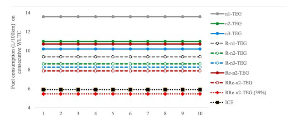
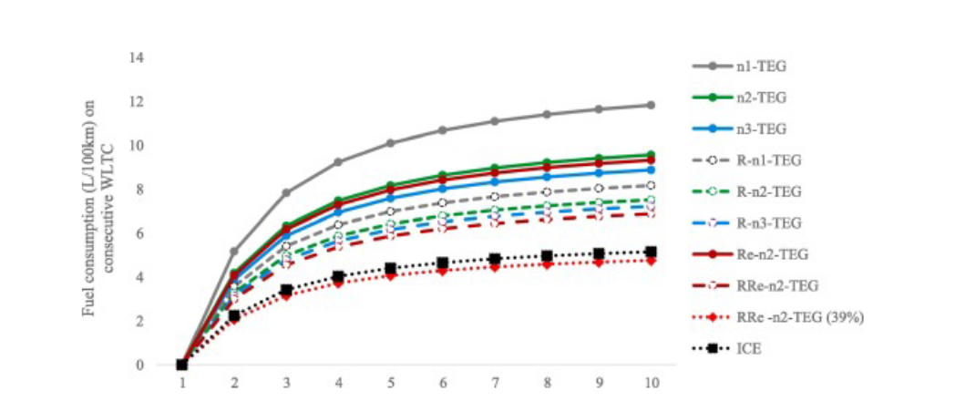
Figure 45: Fuel consumption on plug-in configuration [21]
The study mentioned the feasibility of replacing the traditional internal combustion engine with a thermoelectric generator in automotive powertrains, highlighting the performance in extended-range electric vehicles. [21] When used as auxiliary power units (APUs), simulations comparing TEGs and ICEs reveal that TEGs use 33% more fuel than ICEs. [21] The report does compromise, though, that there is potential for improvements in efficiency, especially in parts of the system like combustors and heat exchangers. [21] Subsequent simulations revealed that the TEG's fuel economy would surpass that of the ICE if the system's efficiency could be raised to 39% (achieved with a benefit factor of ten and a heat recovery efficiency of ninety-two percent). In this instance, the TEG would use 7.7% less gasoline in both configurations than the ICE. [21]
iSupplement information:
17. Kim et al.
Using the TEG, the maximum power output is 119W, with an efficiency of 2.8%, and the pressure declines from 0.45 to 1.46 kPa. [15]
18. Meng et al. (Multiphysics modeling):
The author uses Multiphysics modeling to demonstrate that countercurrent cooling in TEG reduces temperature instability although it can’t improve overall performance. [15] In addition, this shows that using too many thermoelectric units lowers the system's maximum power output. [15] If the spacing between the thermoelectric units remains constant, adding more thermoelectric units can raise the system's maximum power output. [15]
19. Meng et al. (Finite-Time Thermodynamics):
The report highlights the potential for optimizing the TEG system, based on the experience, which illustrates at a temperature of 350 degrees, the 1.47 kW of electrical energy per square meter with a conversion rate of 4.5% happened. [2]
20. Aranguren et al:
The research shows that utilizing heat pipes to boost power by 43%, TEG at the exhaust of a combustion chamber produced a net power output of 21.56 W with an area of 0.25 m^2. [2] This shows just how beneficial it is to add more components to improve the TEG system. [15]
21. Hewawasam et al.
Results show that raising the exhaust gas temperature and exhaust mass flow rate causes the TEG linked to the exhaust muffler to generate more power, emphasizing the importance of optimizing the operating conditions. [15]
22. Ji et al.:
The thermoelectric module height is the most crucial design parameter, followed by length and material, according to ANOVA results. [15]
23. Nithyanandam et al.
The results indicate a critical exhaust flow rate at which the net electric power generated by the thermoelectric generator (TEG) is lower than that of the TEG without metal foam, for varying pore densities of metal foam. [2] When compared to the configuration without metal foam, the maximum net electric power generated from exhaust waste heat by metal foam improved TEG is 5.7 (20 PPI) to 7.8 (5 PPI) times greater. [15]
24. Nour Eddine et al.
The best clamping pressure for the TEG, according to the results, is 0.35 MPa. In comparison to the Silicon-Germanium TEM, the Bismuth-Telluride TEM generated 70% more power output; [15] nevertheless, it quickly degraded when the air inlet temperature rose beyond 300ᵒC, which emphasized the importance of material selection and mechanical design. [15]
25. Remeli et al.
The author emphasizes that efficiency statistics for a particular TEG arrangement in a practical application is provided by combining heat pipes and thermoelectric generators, which showed a heat recovery of 1.345 kW and a power production of 10.39 W utilizing 8 installed TEGs. [15]
26. Tian et al.
The author used simulations to examine the impacts of several variables on conversion efficiency and output power, including the length of the thermocouple, the length ratio between the two materials, exhaust temperature, cold source temperature, and others. [15] The results show that the segmented TEG is more suitable than the standard TEG for high temperature heat sources and extensive temperature changes. [15] It is also noted that as thermocouple length increases, the maximum conversion efficiency rises while the maximum output power decreases. [15] A comparison of the two types of TEGs shows that the segmented TEG has more potential applications for waste heat recovery than the standard TEG. [15]
27. Shu et al.
Utilizing the segmented single-TEMs results in a 13.4% increase in maximum output power over the original. [15] However, the multi-TEMs system outperformed the original model by 30.8%, with a maximum power output of 78.9 W. This indicates that waste heat recovery is more successful when using the multi-TEM mode. [15] It is also mentioned that the heat exchanger's enlarged fins can enhance temperature uniformity and heat transmission. [15]Additionally, the fins changed the best arrangement for the TEMs and raised the maximum power output to 89.7 W. [15]
28. Liu et al.
The article use a new model which reached a maximum output power of 944 W, indicating that, given the right circumstances, substantial power generation is possible. [15]
29. Demir and Dencir:
CaMn0.98Nb0.02O3, La1.98Sr0.02CuO4, and GdCo0.95Ni0.05O3 are three distinct Perovskite-type oxide combination materials. The changes in material characteristics, efficiency, and power produced with regard to temperature and location are examined. [15] The three materials' performance was inferior to that of widely used thermoelectric materials like Bismuth Telluride, but because of their greater temperature performance, they can still be employed as an option for applications comparable to the research. [15]
30. Orr et al:
The power loss resulting from the exhaust pressure decrease was consistently less than the electrical power produced, according to the results. [15]After testing the system in various orientations, it was determined that the bottom heat mode was the optimum choice. [15]After testing, the system's highest output power from the eight TEGs it employed was 38 W. The TEG efficiency was 2.46% and the heat transfer rate was 1541 W. [15]There was a 1.57% chance of reducing CO2 emissions, gasoline usage, and expenses.
3. Conclusion
In conclusion, the paper has provided valuable insights into energy recovery systems, and demonstrated the potential benefits of integrating advanced energy recovery and storage systems in vehicles. The authors have explored various strategies to maximize the efficiency of vehicle energy recovery and improve overall vehicle performance.
• Electric turbochargers offer instantaneous power enhancement and the ability to conserve energy, although they do have higher fuel consumption and emissions compared to traditional turbochargers.
• Flywheel energy storage systems have shown promise in enhancing the efficiency of energy recovery and improving fuel economy. They are cost-effective and reliable solutions that can be integrated into existing systems.
• Regenerative braking is a key technology for improving overall vehicle efficiency by recapturing kinetic energy during deceleration. The study has highlighted the importance of optimizing regenerative braking strategies for different driving conditions to balance energy recovery with vehicle safety.
• Thermoelectric generators have been explored as waste heat recovery devices in vehicles.While their conversion efficiencies are currently lower than other methods, there is potential for improvement through material selection and system optimization.
Overall, this study provides a comprehensive framework for integrating these advanced technologies to achieve better fuel economy, reduce emissions, and improve vehicle performance. Further research could focus on optimizing these technologies for specific applications and exploring new ways to improve the efficiency of vehicle energy recovery.
References
[1]. Kusztelan, A., et al. "A review of novel turbocharger concepts for enhancements in energy efficiency." Int. J. of Thermal & Environmental Engineering 2.2 (2011): 75-82.
[2]. Electric and Hybrid Vehicles - Technologies, Modeling and Control: A Mechatronic Approach-Scientific Figure on ResearchGate. Available from: https://www.researchgate.net/figure/A-schematic-of-a-turbocharging-system_fig8_260878177 [accessed 23 Aug 2024]
[3]. Tang, Qijun, et al. "Study of energy-saving potential of electronically controlled turbocharger for internal combustion engine exhaust gas energy recovery." Journal of Engineering for Gas Turbines and Power 138.11 (2016): 112805.
[4]. Bontempo, Rodolfo, et al. "Highly flexible hot gas generation system for turbocharger testing." Energy Procedia 45 (2014): 1116-1125.
[5]. Bontempo, Rodolfo, et al. "Steady and unsteady experimental analysis of a turbocharger for automotive applications." Energy Conversion and Management 99 (2015): 72-80.
[6]. T. R. S. Kumar, S. B. Koppula, Cr. Prakash, and D. V. Srikanth, “Design and dynamic analysis of Flywheel,” IOSR Journal of Mechanical and Civil Engineering, vol. 16, no. 053, pp. 51–56, Dec. 2016, doi: 10.9790/1684-16053045156.
[7]. A. G. Olabi, T. Wilberforce, M. A. Abdelkareem, and M. Ramadan, “Critical review of Flywheel Energy Storage System,” Energies, vol. 14, no. 8, p. 2159, Apr. 2021, doi: 10.3390/en14082159.
[8]. U. Diego-Ayala, P. Martinez-Gonzalez, N. McGlashan, and K. R. Pullen, “The mechanical hybrid vehicle: An investigation of a flywheel-based vehicular regenerative energy capture system,” Proceedings of the Institution of Mechanical Engineers Part D Journal of Automobile Engineering, vol. 222, no. 11, pp. 2087–2101, Nov. 2008, doi: 10.1243/09544070jauto677.
[9]. A. Boretti, “Modeling of Engine and Vehicle for a Compact Car with a Flywheel Based Kinetic Energy Recovery Systems and a High Efficiency Small Diesel Engine,” SAE Technical Papers on CD-ROM/SAE Technical Paper Series, Oct. 2010, doi: 10.4271/2010-01-2184.
[10]. C. Song, D. Kum, and K.-S. Kim, “Feasibility analysis and performance evaluation of a novel Power-Split flywheel hybrid vehicle,” Energies, vol. 11, no. 7, p. 1744, Jul. 2018, doi: 10.3390/en11071744.
[11]. S. Bai and C. Liu, “Overview of energy harvesting and emission reduction technologies in hybrid electric vehicles,” Renewable and Sustainable Energy Reviews, vol. 147, p. 111188, Sep. 2021, doi: 10.1016/j.rser.2021.111188.
[12]. J. Huh, K. Oh, and D. Shin, “Study of regenerative breaking control for HEV with multispeed transmission,” WEVJ, vol. 7, no. 2, pp. 278–286, Jun. 2015, doi: 10.3390/wevj7020278.
[13]. C. Qiu, G. Wang, M. Meng, and Y. Shen, “A novel control strategy of regenerative braking system for electric vehicles under safety critical driving situations,” Energy, vol. 149, pp. 329–340, Apr. 2018, doi: 10.1016/j.energy.2018.02.046.
[14]. A. O. Ochieng, T. F. Megahed, S. Ookawara, and H. Hassan, “Comprehensive review in waste heat recovery in different thermal energy-consuming processes using thermoelectric generators for electrical power generation,” Process Saf. Environ. Prot., vol. 162, pp. 134–154, Jun. 2022, doi: 10.1016/j.psep.2022.03.070.
[15]. J. K. C. Gavica and R. G. Tayactac, “A Review of Waste Heat Recovery Methods Using Thermoelectric Devices,” in 2024 15th International Conference on Mechanical and Intelligent Manufacturing Technologies (ICMIMT), Cape Town, South Africa: IEEE, May 2024, pp. 63–68. doi: 10.1109/ICMIMT61937.2024.10585981.
[16]. C. Yu and K. T. Chau, “Thermoelectric automotive waste heat energy recovery using maximum power point tracking,” Energy Convers. Manag., vol. 50, no. 6, pp. 1506–1512, Jun. 2009, doi: 10.1016/j.enconman.2009.02.015.
[17]. A. Lekic and D. M. Stipanoviclekic, “Hysteresis Switching Control of the Ćuk Converter Operating in Discontinuous Conduction Modes,” IEEE Trans. Circuits Syst. II Express Briefs, vol. 64, no. 9, pp. 1077–1081, Sep. 2017, doi: 10.1109/TCSII.2016.2631510.
[18]. M. A. Eltawil and Z. Zhao, “MPPT techniques for photovoltaic applications,” Renew. Sustain. Energy Rev., vol. 25, pp. 793–813, Sep. 2013, doi: 10.1016/j.rser.2013.05.022.
[19]. G. Shu, X. Ma, H. Tian, H. Yang, T. Chen, and X. Li, “Configuration optimization of the segmented modules in an exhaust-based thermoelectric generator for engine waste heat recovery,” Energy, vol. 160, pp. 612–624, Oct. 2018, doi: 10.1016/j.energy.2018.06.175.
[20]. S. Lan, R. Stobart, and R. Chen, “Performance comparison of a thermoelectric generator applied in conventional vehicles and extended-range electric vehicles,” Energy Convers. Manag., vol. 266, p. 115791, Aug. 2022, doi: 10.1016/j.enconman.2022.115791.
[21]. W. Bou Nader, “Thermoelectric generator optimization for hybrid electric vehicles,” Appl. Therm. Eng., vol. 167, p. 114761, Feb. 2020, doi: 10.1016/j.applthermaleng.2019.114761.
Cite this article
Zhao,X.;Wang,Y.;Gong,H.;Zhou,L. (2025). A Review of Efficiency and Feasibility for Several Energy Recovery Systems in Automotives. Theoretical and Natural Science,108,1-37.
Data availability
The datasets used and/or analyzed during the current study will be available from the authors upon reasonable request.
Disclaimer/Publisher's Note
The statements, opinions and data contained in all publications are solely those of the individual author(s) and contributor(s) and not of EWA Publishing and/or the editor(s). EWA Publishing and/or the editor(s) disclaim responsibility for any injury to people or property resulting from any ideas, methods, instructions or products referred to in the content.
About volume
Volume title: Proceedings of the 4th International Conference on Computing Innovation and Applied Physics
© 2024 by the author(s). Licensee EWA Publishing, Oxford, UK. This article is an open access article distributed under the terms and
conditions of the Creative Commons Attribution (CC BY) license. Authors who
publish this series agree to the following terms:
1. Authors retain copyright and grant the series right of first publication with the work simultaneously licensed under a Creative Commons
Attribution License that allows others to share the work with an acknowledgment of the work's authorship and initial publication in this
series.
2. Authors are able to enter into separate, additional contractual arrangements for the non-exclusive distribution of the series's published
version of the work (e.g., post it to an institutional repository or publish it in a book), with an acknowledgment of its initial
publication in this series.
3. Authors are permitted and encouraged to post their work online (e.g., in institutional repositories or on their website) prior to and
during the submission process, as it can lead to productive exchanges, as well as earlier and greater citation of published work (See
Open access policy for details).
References
[1]. Kusztelan, A., et al. "A review of novel turbocharger concepts for enhancements in energy efficiency." Int. J. of Thermal & Environmental Engineering 2.2 (2011): 75-82.
[2]. Electric and Hybrid Vehicles - Technologies, Modeling and Control: A Mechatronic Approach-Scientific Figure on ResearchGate. Available from: https://www.researchgate.net/figure/A-schematic-of-a-turbocharging-system_fig8_260878177 [accessed 23 Aug 2024]
[3]. Tang, Qijun, et al. "Study of energy-saving potential of electronically controlled turbocharger for internal combustion engine exhaust gas energy recovery." Journal of Engineering for Gas Turbines and Power 138.11 (2016): 112805.
[4]. Bontempo, Rodolfo, et al. "Highly flexible hot gas generation system for turbocharger testing." Energy Procedia 45 (2014): 1116-1125.
[5]. Bontempo, Rodolfo, et al. "Steady and unsteady experimental analysis of a turbocharger for automotive applications." Energy Conversion and Management 99 (2015): 72-80.
[6]. T. R. S. Kumar, S. B. Koppula, Cr. Prakash, and D. V. Srikanth, “Design and dynamic analysis of Flywheel,” IOSR Journal of Mechanical and Civil Engineering, vol. 16, no. 053, pp. 51–56, Dec. 2016, doi: 10.9790/1684-16053045156.
[7]. A. G. Olabi, T. Wilberforce, M. A. Abdelkareem, and M. Ramadan, “Critical review of Flywheel Energy Storage System,” Energies, vol. 14, no. 8, p. 2159, Apr. 2021, doi: 10.3390/en14082159.
[8]. U. Diego-Ayala, P. Martinez-Gonzalez, N. McGlashan, and K. R. Pullen, “The mechanical hybrid vehicle: An investigation of a flywheel-based vehicular regenerative energy capture system,” Proceedings of the Institution of Mechanical Engineers Part D Journal of Automobile Engineering, vol. 222, no. 11, pp. 2087–2101, Nov. 2008, doi: 10.1243/09544070jauto677.
[9]. A. Boretti, “Modeling of Engine and Vehicle for a Compact Car with a Flywheel Based Kinetic Energy Recovery Systems and a High Efficiency Small Diesel Engine,” SAE Technical Papers on CD-ROM/SAE Technical Paper Series, Oct. 2010, doi: 10.4271/2010-01-2184.
[10]. C. Song, D. Kum, and K.-S. Kim, “Feasibility analysis and performance evaluation of a novel Power-Split flywheel hybrid vehicle,” Energies, vol. 11, no. 7, p. 1744, Jul. 2018, doi: 10.3390/en11071744.
[11]. S. Bai and C. Liu, “Overview of energy harvesting and emission reduction technologies in hybrid electric vehicles,” Renewable and Sustainable Energy Reviews, vol. 147, p. 111188, Sep. 2021, doi: 10.1016/j.rser.2021.111188.
[12]. J. Huh, K. Oh, and D. Shin, “Study of regenerative breaking control for HEV with multispeed transmission,” WEVJ, vol. 7, no. 2, pp. 278–286, Jun. 2015, doi: 10.3390/wevj7020278.
[13]. C. Qiu, G. Wang, M. Meng, and Y. Shen, “A novel control strategy of regenerative braking system for electric vehicles under safety critical driving situations,” Energy, vol. 149, pp. 329–340, Apr. 2018, doi: 10.1016/j.energy.2018.02.046.
[14]. A. O. Ochieng, T. F. Megahed, S. Ookawara, and H. Hassan, “Comprehensive review in waste heat recovery in different thermal energy-consuming processes using thermoelectric generators for electrical power generation,” Process Saf. Environ. Prot., vol. 162, pp. 134–154, Jun. 2022, doi: 10.1016/j.psep.2022.03.070.
[15]. J. K. C. Gavica and R. G. Tayactac, “A Review of Waste Heat Recovery Methods Using Thermoelectric Devices,” in 2024 15th International Conference on Mechanical and Intelligent Manufacturing Technologies (ICMIMT), Cape Town, South Africa: IEEE, May 2024, pp. 63–68. doi: 10.1109/ICMIMT61937.2024.10585981.
[16]. C. Yu and K. T. Chau, “Thermoelectric automotive waste heat energy recovery using maximum power point tracking,” Energy Convers. Manag., vol. 50, no. 6, pp. 1506–1512, Jun. 2009, doi: 10.1016/j.enconman.2009.02.015.
[17]. A. Lekic and D. M. Stipanoviclekic, “Hysteresis Switching Control of the Ćuk Converter Operating in Discontinuous Conduction Modes,” IEEE Trans. Circuits Syst. II Express Briefs, vol. 64, no. 9, pp. 1077–1081, Sep. 2017, doi: 10.1109/TCSII.2016.2631510.
[18]. M. A. Eltawil and Z. Zhao, “MPPT techniques for photovoltaic applications,” Renew. Sustain. Energy Rev., vol. 25, pp. 793–813, Sep. 2013, doi: 10.1016/j.rser.2013.05.022.
[19]. G. Shu, X. Ma, H. Tian, H. Yang, T. Chen, and X. Li, “Configuration optimization of the segmented modules in an exhaust-based thermoelectric generator for engine waste heat recovery,” Energy, vol. 160, pp. 612–624, Oct. 2018, doi: 10.1016/j.energy.2018.06.175.
[20]. S. Lan, R. Stobart, and R. Chen, “Performance comparison of a thermoelectric generator applied in conventional vehicles and extended-range electric vehicles,” Energy Convers. Manag., vol. 266, p. 115791, Aug. 2022, doi: 10.1016/j.enconman.2022.115791.
[21]. W. Bou Nader, “Thermoelectric generator optimization for hybrid electric vehicles,” Appl. Therm. Eng., vol. 167, p. 114761, Feb. 2020, doi: 10.1016/j.applthermaleng.2019.114761.