


1. Introduction
With the development of computer simulation technology, the computational fluid dynamics (CFD) method, which uses computers to solve the flow field in the field of racing cars, is being applied more and more. Among the aerodynamic components of a racing car, the rear wing, also known as the rear spoiler, is a key component that affects the aerodynamic characteristics of the car. The rear spoiler has a great influence on the aerodynamic characteristics of the car, such as changing the aerodynamic drag force coefficient and negative lift coefficient. The use of rear spoiler can effectively increase downforce without adding too much weight. This can help improve the car’s grip and ensure a stable ride on a complex track. However, negative lift is often accompanied by resistance generation, so it is necessary to coordinate the two aerodynamic characteristics of negative lift and drag force to make the spoiler perform at its best.
At present, some researchers have carried out research on the aerodynamic components of racing cars. For example, Mao Xu [1] et al. adopted the numerical simulation method to conduct aerodynamic analysis and comparison of structural parameters such as the airfoil, angle of attack, and ground clearance of the rear spoiler of F1 racing cars. The negative lift and drag force characteristics of the rear spoiler are studied, and it is found that the airfoil with a larger curvature and a thicker wing body is the optimal solution. In the study of Bai Qiuyang et al. [2], based on Renault mean turbulence equation and Realizable k-ε turbulence model, a three-dimensional model of the car's outflow field was established. The orthogonal experimental design method was used to analyze the degree of influence of different car kit combinations on the car, and it was found that the rear spoiler was the most important for the aerodynamic characteristics of the car. In the study of Mustafa Cakir et al. [3], researchers placed different spoilers in different positions at the back end of the 3D computer model vehicle and conducted numerical analysis through CFD. Finally, it was found that the rear spoiler only had positive effects at high velocities, while the other side would have more negative effects. In the study of Kurec et al. [4], they analyzed a scheme that can quickly change the aerodynamic load on the body and wing, in which two movable spoilers are used, which requires less energy and has a very fast response.
In the above studies, only conventional factors such as velocity and angle of attack were considered, but other factors such as altitude and airfoil were not taken into account. In this paper, aiming at different airfoils and altitude conditions, commercial software Ansys AIM is used as a CFD simulation tool to conduct numerical simulations of the rear spoiler under different working conditions and recommend airfoils that are more suitable for different tracks. Compared with many model studies on the material and angle of attack of the rear spoiler itself, this paper will increase the influence of different airfoils and track altitudes on the rear spoiler based on previous track reports.
2. Calculation Models
2.1. Geometric Constructions
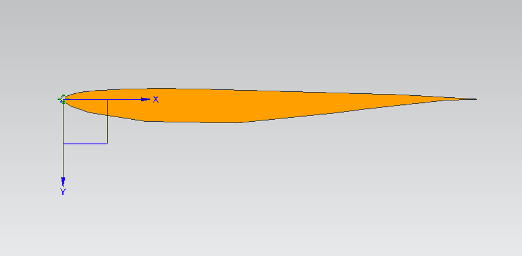
This article uses the Eppler E58 low Reynolds number airfoil, the Eppler E182 low Reynolds number airfoil, the Eppler E220 low Reynolds number airfoil, and the Eppler E374 low Reynolds number airfoil as the main research objects. The airfoil data comes from the airfoil dataset of UIUC [5], and the point sets are connected into smooth curves by polynomial curve fitting. The basic geometry of its cross section is shown in Figure 1.
|
(a) Eppler E182 low Reynolds number airfoil. |
|
(b) Eppler E220 low Reynolds number airfoil. |
|
(c) Eppler E374 low Reynolds number airfoil. |
|
(d) Eppler E58 low Reynolds number airfoil. |
Figure 1. Display of cross section geometry of four airfoils. |
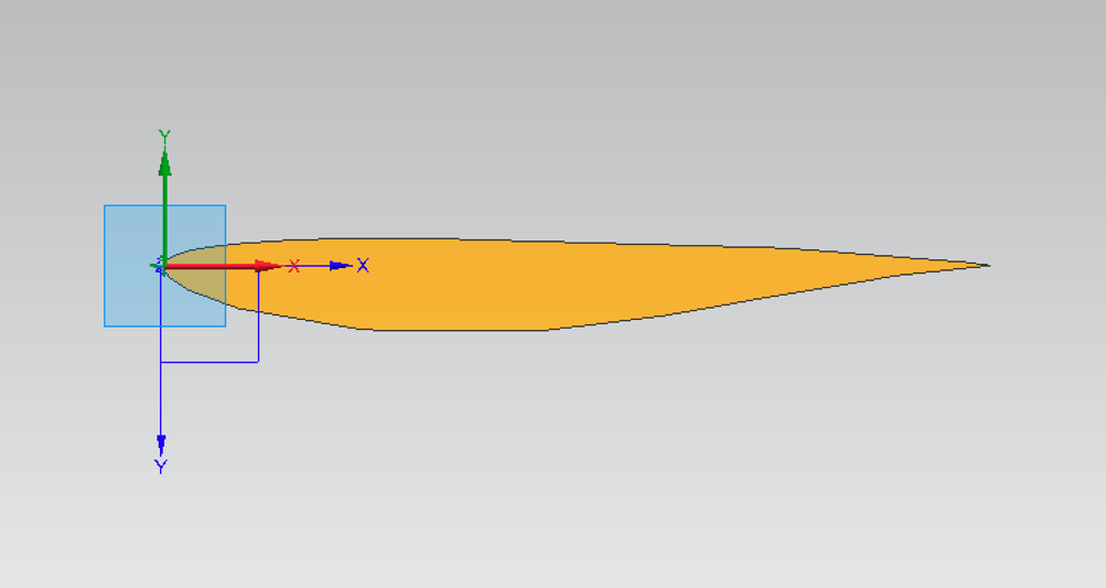
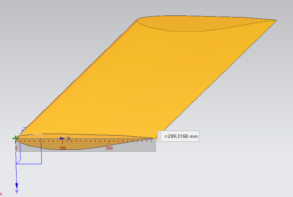
In order to ensure the fairness of the FIA Formula 1 World Championship, the size of the aerodynamic device that affects speed is limited. According to the general regulations [6] issued by the FIA, the sponsor of the competition, the rear spoiler overhang shall not exceed 1000mm, the width of the rear spoiler shall not exceed 500mm, and the height shall not exceed 800mm. Therefore, the width and length of the four airfoils are set at 300 mm and 500 mm, respectively. Take airfoil 2 as an example; its size is shown in Figure 2.
|
Figure 2. Eppler E220 Airfoil 3D display (300mm width). |
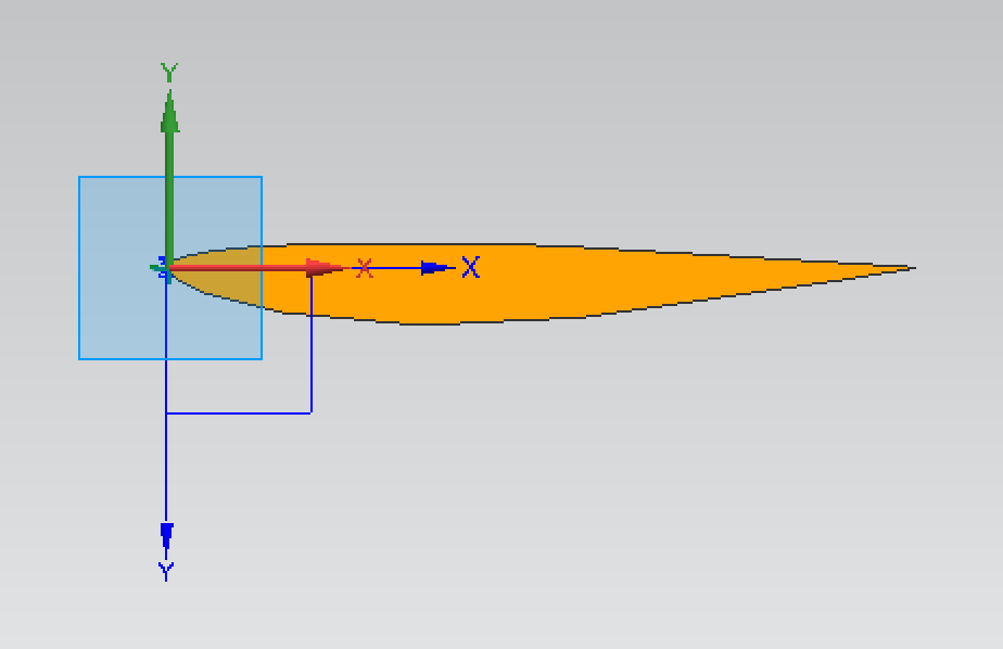
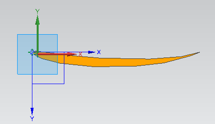
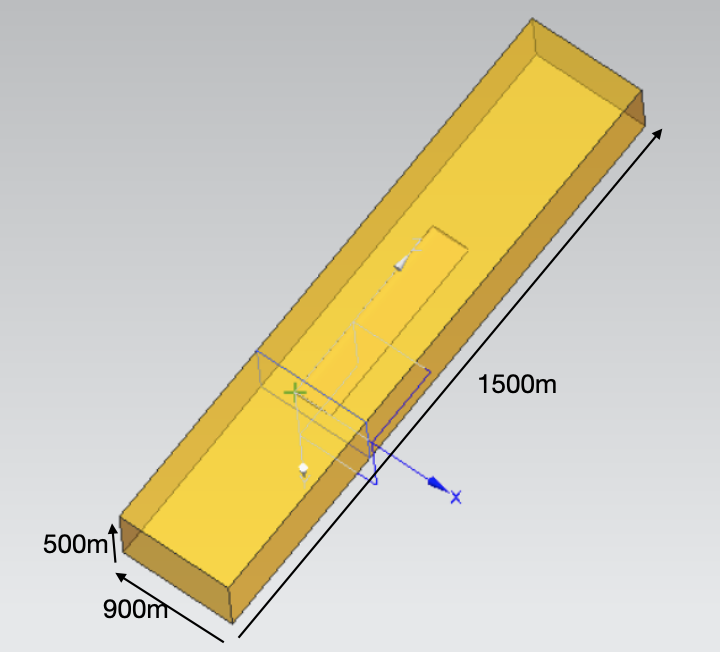
Since the actual CFD calculation is the outflow field of the rear spoiler, we first use 3D modelling software to establish the calculation domain of the peripheral flow field. In order to avoid the influence of the wall effect on the calculation as much as possible and not increase the amount of calculation, we finally chose a more appropriate size of the outflow field: its width and length are 900mm and 1500mm, respectively, and its height is 10 times the airfoil height, as shown in Figure 3.
|
Figure 3. Outflow field diagram of Eppler E220 airfoil (length, width and height: 1500mm, 900mm, 500mm). |
2.2. The Basic Theory of Computational Fluid Dynamics
The essence of the CFD method is to use the numerical discrete method to solve N-S equations. The basic form of N-S equations such as Equation 1:
\( \frac{Dφ}{Dt}≡\frac{∂φ}{∂t}+u\cdot ∇φ \) (1.a)
\( \frac{DA}{Dt}≡\frac{∂A}{∂t}+u\cdot ∇A \) (1.b)
In most cases, the N-S equation cannot be solved directly. Therefore, we need to use the RANS method for simplification and numerical discretization in order to obtain the numerical solution available in engineering. In this paper, the general fluid solver in Ansys is selected as the discrete solution to analyze the influence of different boundary conditions on the aerodynamic performance of the rear spoiler, namely, the negative lift and drag force.
Negative lift and drag force are units of value, usually N or N/m2, which is Pa. The dimensionless negative lift coefficient and drag force coefficient are expressed in Equation 2.
The expression of the negative lift coefficient is
\( {C_{p}}=\frac{{F_{p}}}{\frac{1}{2}ρυ_{∞}^{2}A} \) (2.a)
The expression of drag force coefficient is
\( {C_{d}}=\frac{{F_{d}}}{\frac{1}{2}ρυ_{∞}^{2}A} \) (2.b)
Among this, \( {C_{p}} \) represents the negative lift coefficient; \( {C_{d}} \) represents the drag forcecoefficient; \( {F_{d}} \) represents the wind drag force; \( {F_{p}} \) represents the negative lift; \( ρ \) represents the air density; \( {υ_{∞}} \) represents the velocity of a racing car; \( A \) represents the car orthographic projection area.
2.3. The Numerical Model
The Ansys AIM software was used for grid division, considering the grid-independent solution and using several groups of grids of different sizes for research. Finally, the total number of 1.6 million grids was selected as the solution grid.
The boundary conditions are speed inlet and pressure outlet. The specific pressure depends on the local atmospheric pressure. The air is the fluid in the flow field, and since the car is still running at a slower speed, below 0.3Ma, it can be considered an incompressible fluid. The solver selects the pressure base solver, the convergence criterion is determined by the software, and the default is 1e-3. The turbulence model is SST k-ω.
2.4. Variable Selection: Track Conditions
Since the variables of angle of attack and velocity of the rear spoiler have been studied in detail by predecessors, this paper does not focus on the factors of angle of attack and velocity. In the constructed calculation model, this paper focuses on the track factor and airfoil factor. The speed is fixed at 72 m/s, and the angle of attack is fixed at 15°. The following are classic F1 racetracks with outstanding characteristics. By analyzing the characteristics of corners and straights, the negative lift and drag force have different demands, leading to different airfoil selection biases.
Track one: Spa-Francolchamp. In Belgium, the track is characterized by multiple curves, such as continuous S bending, hairpin curves, and so on. The circuit has a length of 7.05 kilometers per lap, so it can be rainy and sunny at the same time due to geographical factors. Under these conditions, the driver should choose a medium-negative lift setting to ensure that the car does not skid. The negative lift factor is slightly higher than the drag force factor.
Track two: The Rodriguez Brothers Track. The track is on the plateau in southern Mexico, as high as 2234 meters above sea level. In a plateau environment, the air density is low, and the requirements for a rear spoiler are different from those on a flat track. The low density of the air means low drag force, so here the cars are running at unprecedently high straight speeds. The car should be set to the highest negative lift; otherwise, the grip will be very low and the safety risk is very high. The negative lift factor is much higher than the drag force factor at this track.
Track three: Silverstone. This circuit, located in London, England, has a long straight line and high-speed corners. Under these track conditions, this type of driver should try to choose a rear spoiler with a low drag force to ensure that the car is moving at a high speed and does not need too much negative lift to keep the body stable. The drag force factor is higher than the negative lift factor on this track.
3. Results and Analysis
We considered the combination of four airfoil types and three altitudes, which directly affected the air density. The air density of track 1 was set to 1.15 kg/m3, track 2 was set to 1.005 kg/m3, and track 3 was set to 1.293 kg/m3 to analyze the most suitable airfoil under different track conditions. All inlet velocities were set at 72 m/s, and all attack angles were fixed at 15°. A total of 3*4=12 working conditions were calculated, and the results were as follows.
3.1. Flow Field Analysis
Take the Silverstone track as an example, where the altitude is low, the atmospheric pressure is set at 101325Pa, and the air density is set at 1.15 kg/m3. The velocity field and pressure distribution of four different airfoil types are shown in Figures 4–7.
|
|
(a) velocity cloud image | (b) pressure cloud image |
Figure 4. Velocity and pressure distribution cloud images of airfoil 1. | |
|
|
(a) velocity cloud image | (b) pressure cloud image |
Figure 5. Velocity and pressure distribution cloud images of airfoil 2. | |
|
|
(a) velocity cloud image | (b) pressure cloud image |
Figure 6. Velocity and pressure distribution cloud images of airfoil 3. | |
|
|
(a) velocity cloud image | (b) pressure cloud image |
Figure 7. Velocity and pressure distribution cloud images of airfoil 4. | |
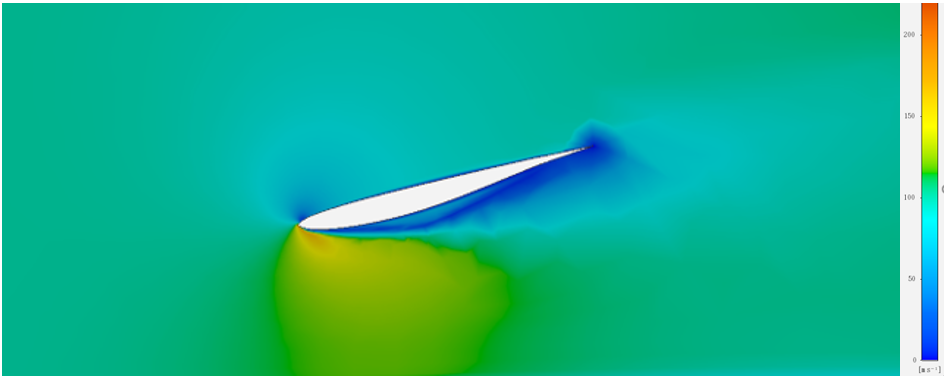
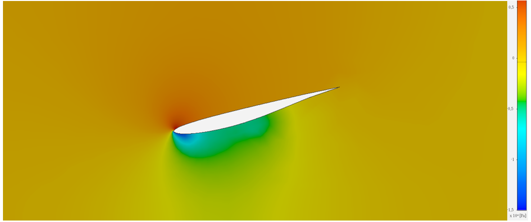
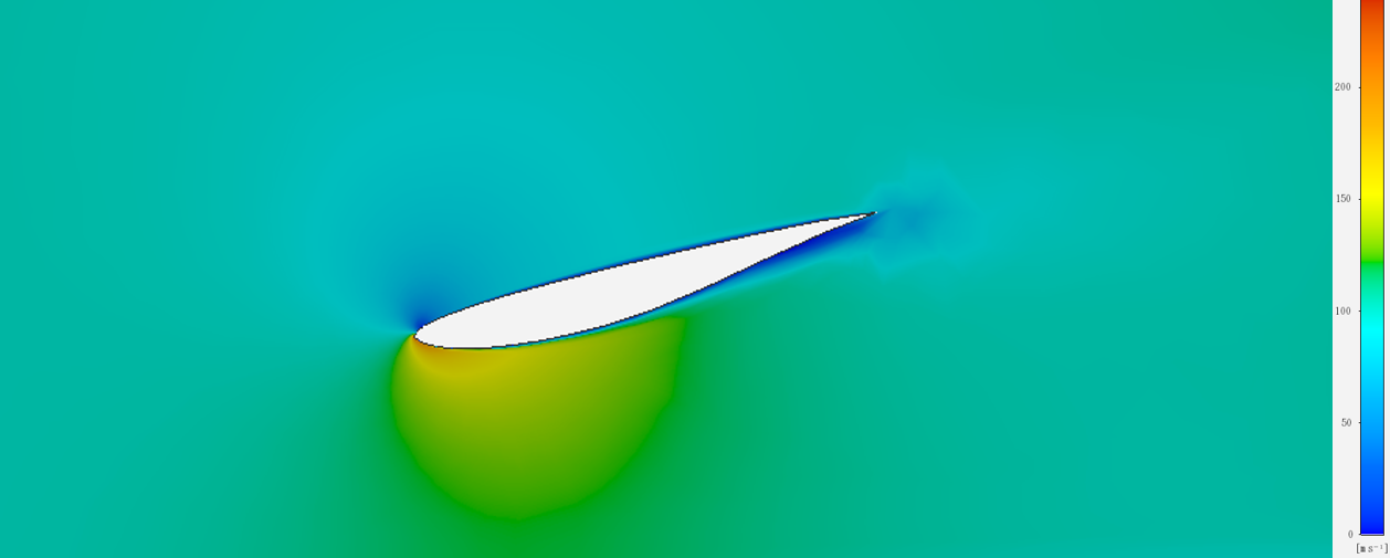
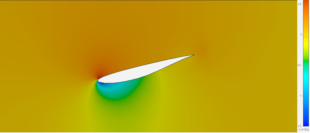
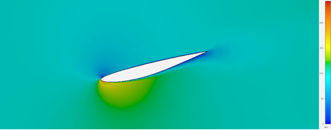
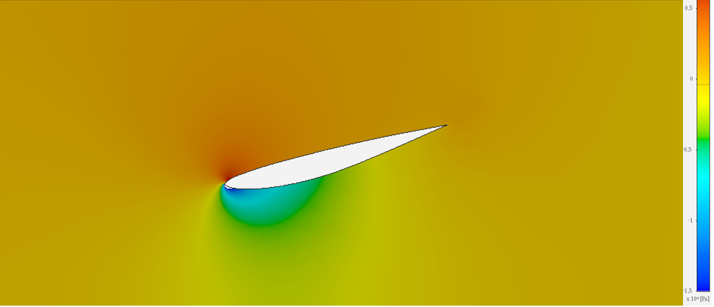
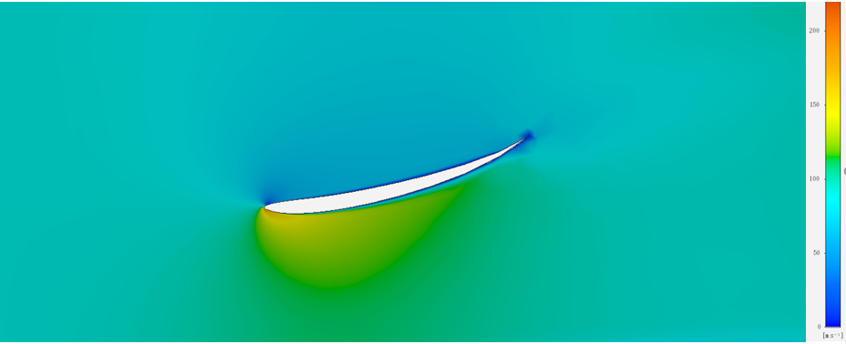
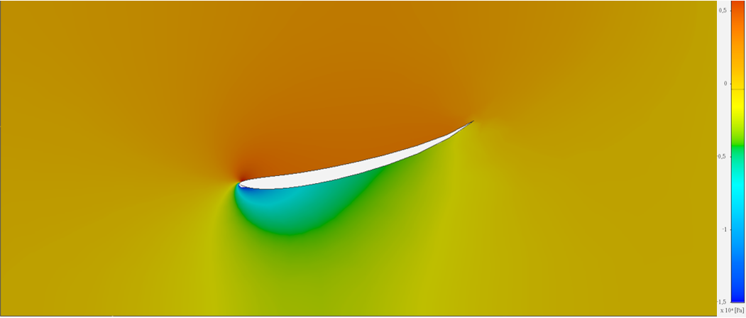
It can be seen from the figures that, among the four airfoils, there is a strong flow separation phenomenon at the suction surface of airfoil 1, resulting in a small negative lift force. There is little difference between airfoil 2 and airfoil 3, while airfoil 4 has a large adverse pressure gradient on the pressure surface, so its negative lift and drag force are both larger, which is related to the unique concave shape of airfoil 4.
3.2. The Aerodynamic Performance of Different Airfoils
Drag force and negative lift characteristics of different airfoils on three tracks are shown in Figures 8 and 9.
|
Figure 8. Drag force characteristics of different airfoils on different tracks. |
|
Figure 9. Negative lift characteristics of different airfoils on different tracks. |
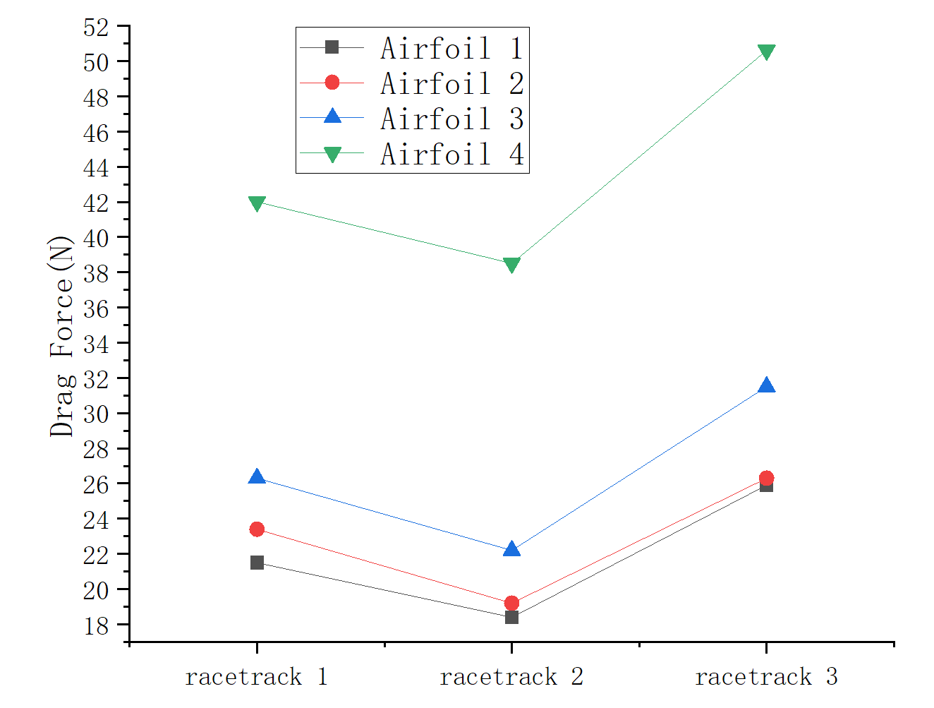
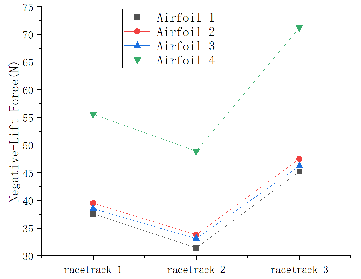
From figures 8 and 9, it can be seen that track 3 in London has a higher drag force and negative lift, which are related to the higher air density, while track 2 in the plateau area has the opposite effect. Among the four airfoils, airfoil 4 had a far higher drag force and negative lift than the other three, and airfoil 1 had the smallest drag force and negative lift. Compared with airfoil 2 and airfoil 3, it can be seen that the drag force generated by airfoil 3 is slightly greater than that of airfoil 2, but the negative lift generated by airfoil 3 is smaller than that of airfoil 2, so its performance is poor.
Based on qualitative analysis and the matching of airfoils with the aerodynamic performance required by each circuit, this paper suggests using airfoil 2 on track 1: Spas-Francolchamp, airfoil 4 on track 2: Rodrigues Brothers, and airfoil 1 on track 3: Silverstone.
4. Conclusions
Quantitative data can be obtained at a fixed speed of 72m/s and an angle of attack of 15 degrees:
In track 1, the specific negative lift value of airfoil 2 is 38N and the drag is 26.5N. The airfoil has a moderate negative lift value and a slightly lower drag value, making it best suited for track one.
In track 2, the specific negative lift value of airfoil four is 49N and the drag is 39N. The airfoil is of high negative lift among the four airfoils, which improves the grip of the car at high altitude and effectively increases the safety. It is suitable for the track II at high altitude.
In track 3, the negative lift value of airfoil one is 45N and the drag value is 26N. The smaller the drag of the airfoil, the more suitable it is. The grip provided by the negative lift value is relatively unimportant. Therefore, under this track, airfoil one with the lowest drag value is the best fit for track three.
Through the above research, the following conclusions can be drawn:
1. Both the drag force and negative lift generated by the rear spoiler are negatively correlated with air density. The higher the altitude, the thinner the air density, and the lower the drag force and negative lift generated
2. Among the four airfoils studied in this paper, airfoil 4 had the strongest negative lift ability, while airfoil 1 had the weakest. The same rule applies to drag force.
3. Airfoil 2 is selected for track 1, airfoil 4 for track 2, and airfoil 1 for track 3.
Due to limited computing resources, this study only considers the case of fixed velocity and fixed angle of attack for the time being, and fails to carry out numerical simulation in more dimensions. In the future, the study of airfoil can consider other variable space more. For example, different angles of attack, different speeds and other variables can be added to simulate more real track conditions, so as to carry out a more comprehensive study.
References
[1]. Mao Xu, Wu Ningning. Improved aerodynamic performance of the new rear spoiler model of the FSAE Racing car [J]. Mechanical Science and Technology, 2014,33(09):1397-1402. DOI:10.13433/j.cnki.1003-8728.2014.0924.
[2]. Hu Li, Luo Shimin, Yang Qiliang, et.al. The aerodynamic package design of Formula racing car [J]. Journal of Wuhan University of Science and Technology (Natural Science), 2015(5):377-380. DOI: 10.3969/j.issn. 1674 - 3644.2015.05.013.
[3]. Dey S , Saha R . CFD Study on Aerodynamic Effects of NACA 2412 Airfoil as Rear Wing on a Sports Car[C]// International Conference on Mechanical, Industrial and Energy Engineering 2018. 2018.
[4]. Kurec K , Remer, Michał, Mayer T , et al. Flow control for a car-mounted rear wing[J]. International Journal of Mechanical Sciences, 2018.
[5]. UIUC airfoil dataset. https://m-selig.ae.illinois.edu/ads.html.
[6]. Principles issued by FIA. https://www.formula1.com/
Cite this article
Zhang,C. (2023). Research on the aerodynamic performance of the F1 racing car rear spoiler with different track characteristics. Theoretical and Natural Science,5,839-846.
Data availability
The datasets used and/or analyzed during the current study will be available from the authors upon reasonable request.
Disclaimer/Publisher's Note
The statements, opinions and data contained in all publications are solely those of the individual author(s) and contributor(s) and not of EWA Publishing and/or the editor(s). EWA Publishing and/or the editor(s) disclaim responsibility for any injury to people or property resulting from any ideas, methods, instructions or products referred to in the content.
About volume
Volume title: Proceedings of the 2nd International Conference on Computing Innovation and Applied Physics (CONF-CIAP 2023)
© 2024 by the author(s). Licensee EWA Publishing, Oxford, UK. This article is an open access article distributed under the terms and
conditions of the Creative Commons Attribution (CC BY) license. Authors who
publish this series agree to the following terms:
1. Authors retain copyright and grant the series right of first publication with the work simultaneously licensed under a Creative Commons
Attribution License that allows others to share the work with an acknowledgment of the work's authorship and initial publication in this
series.
2. Authors are able to enter into separate, additional contractual arrangements for the non-exclusive distribution of the series's published
version of the work (e.g., post it to an institutional repository or publish it in a book), with an acknowledgment of its initial
publication in this series.
3. Authors are permitted and encouraged to post their work online (e.g., in institutional repositories or on their website) prior to and
during the submission process, as it can lead to productive exchanges, as well as earlier and greater citation of published work (See
Open access policy for details).
References
[1]. Mao Xu, Wu Ningning. Improved aerodynamic performance of the new rear spoiler model of the FSAE Racing car [J]. Mechanical Science and Technology, 2014,33(09):1397-1402. DOI:10.13433/j.cnki.1003-8728.2014.0924.
[2]. Hu Li, Luo Shimin, Yang Qiliang, et.al. The aerodynamic package design of Formula racing car [J]. Journal of Wuhan University of Science and Technology (Natural Science), 2015(5):377-380. DOI: 10.3969/j.issn. 1674 - 3644.2015.05.013.
[3]. Dey S , Saha R . CFD Study on Aerodynamic Effects of NACA 2412 Airfoil as Rear Wing on a Sports Car[C]// International Conference on Mechanical, Industrial and Energy Engineering 2018. 2018.
[4]. Kurec K , Remer, Michał, Mayer T , et al. Flow control for a car-mounted rear wing[J]. International Journal of Mechanical Sciences, 2018.
[5]. UIUC airfoil dataset. https://m-selig.ae.illinois.edu/ads.html.
[6]. Principles issued by FIA. https://www.formula1.com/