


1. Introduction
Earthquakes can lead to catastrophic building collapses, causing significant loss of life and property damage. Understanding the response of different building structures to seismic activity is therefore essential for enhancing their resilience and reducing the risk of such disasters. While past research has largely focused on the vibration response of metal and concrete structures, little attention has been paid to wooden structures with mortise-tenon joints. These joints, which rely on friction rather than glue or screws, can offer flexibility and potentially enhance a building's earthquake resistance.
Although technology advances every day, some ancient building structures have survived longer than newly built ones with the contribution of the stability of mortise-tenon structures. Mortise-tenon joints consist of two pieces: the mortise hole and the tenon tongue. By connecting those two pieces together, they can form a stable joint. The Forbidden City, located in Beijing, China, was constructed in the 15th century and has experienced hundreds of earthquakes, including several high-magnitude earthquakes. The Forbidden City survived the deadly Tangshan earthquake in 1976, which had a magnitude of 7.6 [1]. The structure of the building gathered the wisdom of ancient architects who used mortise-tenon joints and high-quality wood to construct the entire building. Mortise tenon joints provide a stable and flexible frame, being able to afford a greater load and a higher deformation [2]. Researchers later constructed a model of the Forbidden City and subjected it to earthquake simulations [3]. As they increased the shaking magnitude, the model started from mild shaking to base shifts, and finally, at a 10.1 magnitude, both sides of the masonry collapsed [2]. Despite this, the central structures remained firm and only experienced minimal displacement, even as the side walls fell apart.
To mitigate the effects of vibration during earthquakes, a common approach is to enhance damping [4]. In earthquakes that have occurred in China, many buildings that sustained minimal damage were made of wood and connected using mortise-tenon joints. These joints, made of wood, are flexible as they are not secured with glue or screws.
The purpose of this paper is to investigate the earthquake resistance of wooden structures with mortise-tenon joints compared to modern structures, using a low-cost sensor system developed specifically for educational purposes. We examine the impact of two different damping mechanisms, material damping, and frictional damping within flexible joints, on earthquake resistance, and simulate the response of a real earthquake based on our findings. The research aims to contribute to the study of mortise-tenon joints' earthquake response and provide a possible way to help reduce the risk of building collapses and property damage during significant earthquakes.
The research is organized into six sections. In Section 1, the literature background is presented, along with an introduction to the experiments, placing special emphasis on the educational rationale behind the development of the low-cost system. Moving to Section 2, the methods employed to examine damping are discussed, followed by the description of the sensor system's development in Section 3. Transitioning to Section 4, an exploration is conducted to assess the impact of the frictional damping within flexible mortise-tenon joints on earthquake resistance. Section 5 leverages the insights gained from Section 4 to simulate the response of a real earthquake. Ultimately, the research concludes in Section 6, summarizing the findings and providing future perspectives.
2. Methodology
Damping is an important characteristic of a structure that represents its ability to dissipate energy and return to its original state after experiencing a vibration. Higher damping ratios indicate better energy dissipation and reduced levels of vibration, which can help minimize damage during earthquakes [5].
To evaluate damping, impact hammer tests were conducted assuming the linear behavior of the building during earthquakes. The instrumented force hammer was used to strike specific locations of the building structure, generating accelerations with similar orders of magnitude as those experienced in real earthquakes. The accelerometers (Vernier Low-g accelerometer) were used to measure the acceleration response at different locations in the building. All sensors were connected to the LabQuest DAC card.
The impact hammer tests provided a relative broadband flat force excitation, with a consistent signal-to-noise ratio throughout the frequency range of interest. To avoid double hits during testing, 8 out of 10 sets of acceleration data were selected for ensemble averaging (see Figure 1), from which the frequency response function (FRF) graph was obtained (see Figure 2).
The response time history obtained from the impact hammer tests was first transformed to the frequency domain using the Fourier transform (see Figure 3). This allowed the accelerance (Acceleration over Force) versus frequency data to be collected. Accelerance is a characteristic of a structure that remains constant regardless of the excitation forces applied. By analyzing the FRF graphs, the damping of the structure was obtained using the half-power method. This method involves finding the frequency at which the power spectral density (PSD) of the response is half its maximum value. This frequency corresponds to the natural frequency of the structure, and the corresponding damping ratio can be calculated using the bandwidth between the two frequencies where the PSD is half its maximum value. This method provides a reliable and accurate way to evaluate the damping of a structure.
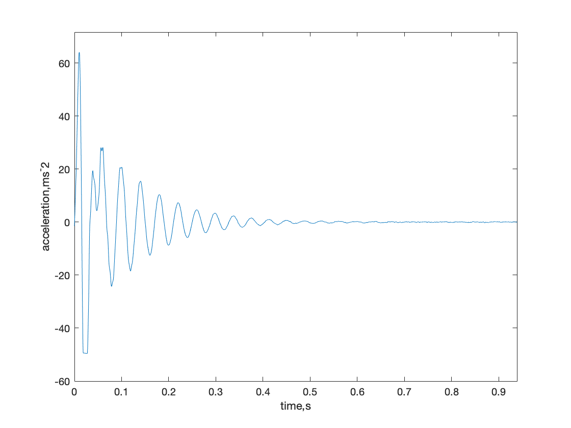
Figure 1. Acceleration data we got from experiments.
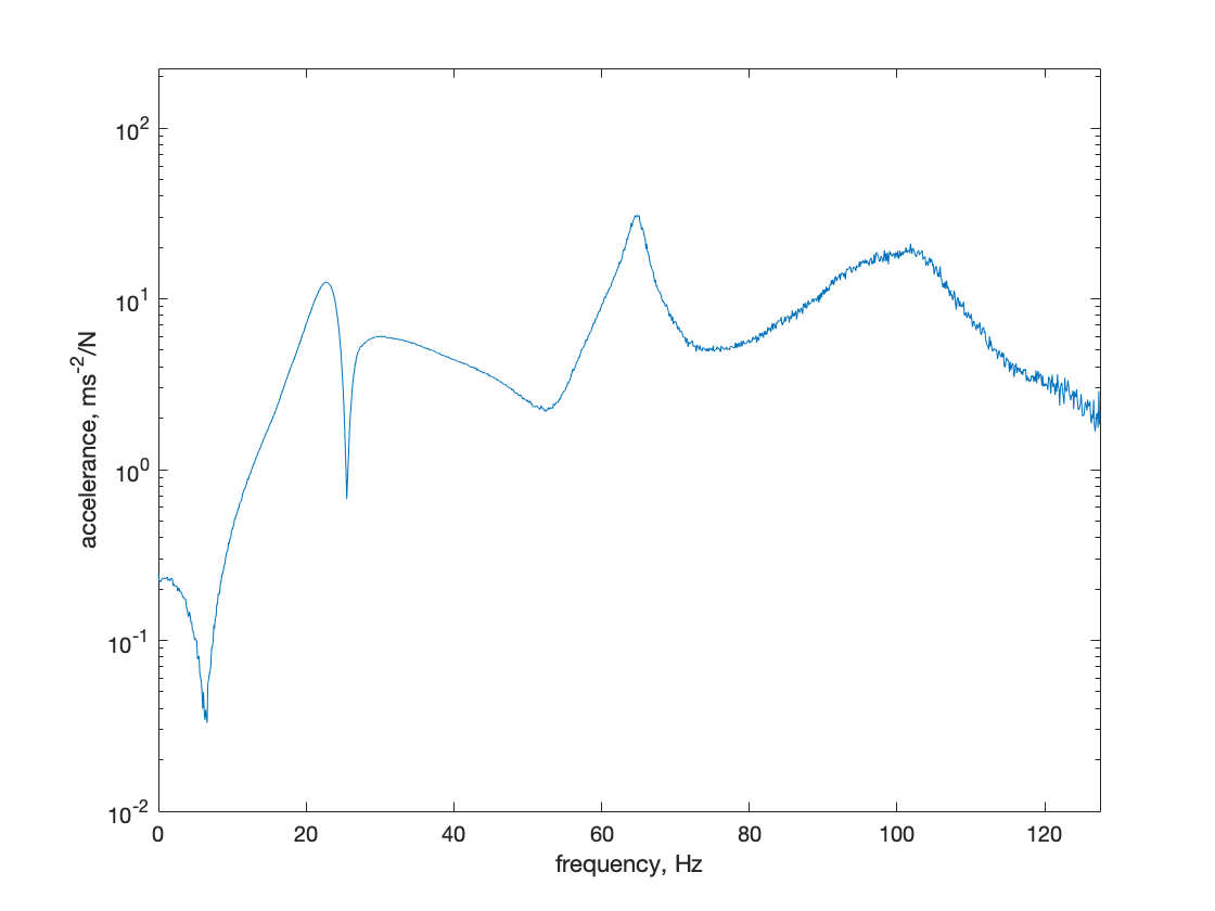
Figure 2. FRF graph; half-power method to get damping.
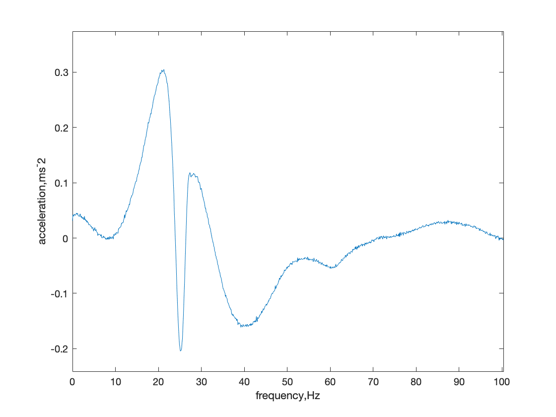
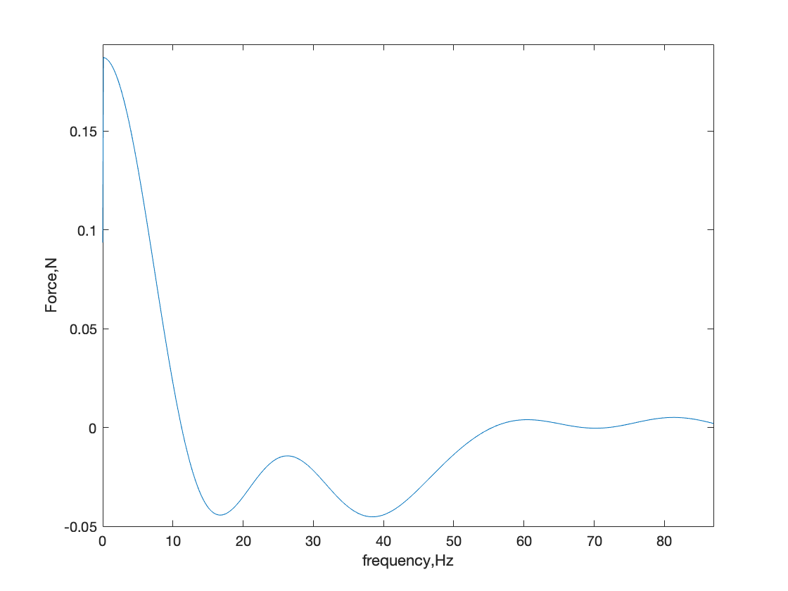
Figure 3. Demonstration of getting FRF: (a) acceleration data in frequency domain (b) force data in frequency domain.
3. Development of the Low-Cost Data Acquisition System
In this section, the development of a low-cost sensor system is presented for evaluating the dynamic response of civil structures. Due to limited resources available to high school students, accelerometers, hammers, and simple structural materials are used to develop the system.
3.1. Development of an Instrumented Hammer
To investigate earthquake resistance, researchers often use expensive shaker tables to simulate earthquakes [6]. However, an instrumented hammer was developed as a low-cost alternative to assess the dynamic response of civil structures. The hammer comprises a standard hammer head with an accelerometer attached to its head, which records the acceleration response of the structure to the impact. The impact force can be obtained by applying Newton’s Second Law:
\( F={m_{head}}{a_{hammer}}\ \ \ (1) \)
Since the weight of the hammerhead is difficult to measure accurately, a validation rig (see Figure 4) was established to obtain the sensitivity value.
\( S=\frac{{F_{impact}}}{{a_{hammer}}}\ \ \ (2) \)
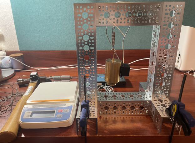
Figure 4. Calibration test rig for the impact force: experimental rig.
The validation rig consists of a metal frame built with six U-channels and screws, along with coil spring and a mass of 550 g hung onto it using a hook. A 16 oz claw hammer was used as an impact hammer. Two accelerometers were attached to measure the acceleration data: a 25-g accelerometer on the side of the hanging mass and a low-g accelerometer on the hammerhead. The accelerometers were connected to a LabQuest with a 2000 sampling rate to record the data for 10 seconds.
Based on the acceleration spectrum presented in Figure 3, the acceleration at both the hammer and the mass exhibit similar trends between 10 Hz and 40 Hz. In the range of 0 to 10 Hz, the structure exhibits resonance behavior, and in 40 Hz to beyond, the signal-noise ratio is very low. Therefore, 10 to 40 Hz was used as the testing sample (see Figure 5). By averaging the acceleration values within this range, the acceleration of the hammer and the mass were found to be 3.1377 × 10⁻⁴ m/s2 and 4.8356 × 10⁻⁴ m/s2, respectively. Using the mass of the hanging mass, which is 550 g, the force acting on the mass is calculated to be 2.7466 × 10⁻⁴ N. The sensitivity of the hammer can be calculated using Equation 2, resulting in a sensitivity value of 0.8754.
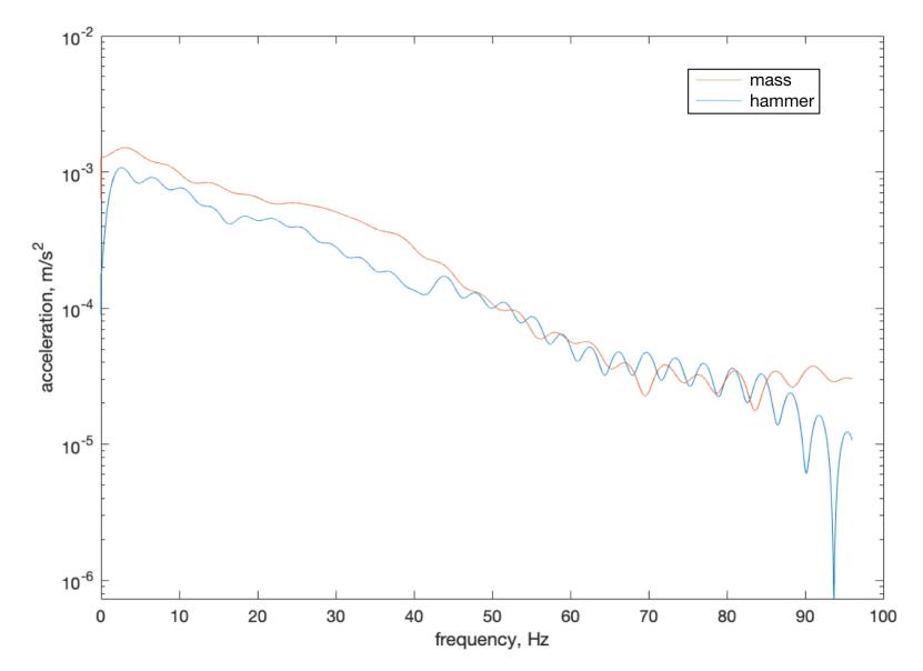
Figure 5. Force spectrum for the acceleration at mass and hammer.
3.2. Verification of the Accuracy of the Sensor System with Cantilever Beam Tests
Finite Element Modal Analysis is an accurate method to simulate the vibration and characteristics of a simple structure. Hence, it was used here to validate whether the resonance frequency of a simple cantilever ruler could be evaluated using this low-cost data acquisition system (see Figure 6). Following this, Finite Element Transient Analysis was introduced to validate whether an accurate acceleration response can be obtained for this low-cost system.
To set up the system, a composite ruler with dimensions of 310 mm × 37 mm × 1.55 mm and a weight of 72.2 g was used. For this ruler, the material properties are shown in Table 1.
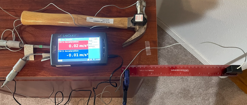
Figure 6. Cantilever beam test set-up.
Table 1. Mechanical properties of the ruler.
Young’s modulus, GPa | 27.6 |
Poisson’s ratio | 0.2 |
Density, kg/m3 | 2223 |
Weight of the sensor, g | 18 |
To evaluate the accuracy of the sensor system, a ruler was secured on a table with one end clamped, and a low-g accelerometer was affixed to the other end to record its acceleration. The middle of the ruler was struck with an instrumented hammer to induce free vibration, and the resulting acceleration Frequency Response Function (FRF) was obtained (see Figure 7) to estimate the natural frequency and damping of the system. To further validate the results, a Finite Element Modal Analysis was performed using the ruler model with a point mass added to the tip, which is used to simulate the additional weight of the accelerometer, to obtain the natural frequency of the simulated model. The simulated natural frequency was then compared to the experimental data to verify the accuracy of the sensor system.
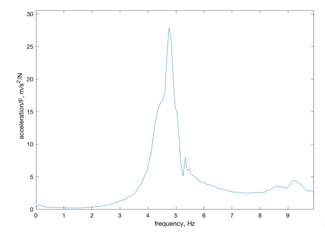
Figure 7. Acceleration FRF for the composite ruler.
The FRF graph of the ruler indicated that the peak natural frequency was 4.566 Hz, and the damping was 0.0875. Figure 8 illustrates that the simulated peak resonance frequency was 4.7749 Hz, which closely matched the actual frequency from the experiment.
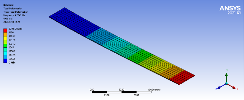
Figure 8. Mode shape of the 1st resonance from Finite Element modal analysis.
Using the identified impact force history and the damping, Finite Element Transient Analysis was employed to generate a simulated acceleration time history for the ruler (see Figure 9). Although the experimental and simulated acceleration time histories exhibited similar vibration responses, it is worth noting that the weight of the accelerometer may have caused some pre-deformation of the ruler, which could have influenced the vibration response. As a result, the peaks in the experimental curve were slightly lower than those in the simulation. Nonetheless, the overall agreement between the two data sets indicates that the sensor system has reasonable accuracy and reliability for measuring the vibration characteristics of simple structures such as the cantilever ruler tested here.
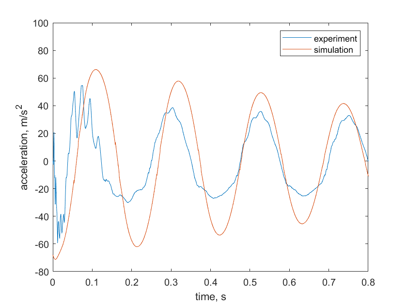
Figure 9. Comparison of the acceleration time history between the experiment and simulation.
4. Investigations of Energy Dissipation in Traditional Chinese Architecture
4.1. Investigation of the Energy dissipation within Mortise-Tenon Joints
This section introduces the experimental framework used to investigate frictional damping within mortise-tenon joints, employing two distinct building models tailored for this purpose. The underlying methodology presents a meticulous approach to comprehending this damping phenomenon. This experimental approach emphasizes the rationale for selecting these models and their pivotal role in achieving our research objectives. Through this meticulously arranged experimental setup, the study delves into the intricate behaviors exhibited by mortise-tenon joints, with particular attention to their contribution to the frictional damping.
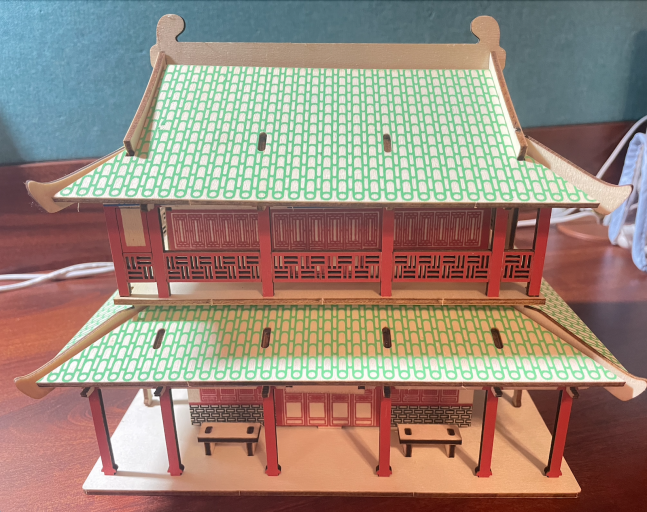
Figure 10. Mortise-tenon-joint building model (flexible joint).
Prior to the experimental phase, two building models featuring mortise-tenon joints were built. The dimensions of these models were 235 mm × 172 mm × 170 mm, as illustrated in Figure 10. Within the one of the building models, all wooden components were joined without the use of glue, allowing them to exhibit relative movements that generate frictional damping. In the other model, the joints were glued. To establish conditions of free motion, an assembly of eight U-channels was created using metal. Positioned at the upper part of this assembly were two parallel U-channels, providing a suspension mechanism for both the building model and the acrylic board. This experimental setup enabled an in-depth exploration of the frictional damping behavior within the mortise-tenon joint. Implementing a free-suspension boundary condition for a building model can provide a more realistic representation of the structure's behavior during earthquake excitation. In real-world scenarios, buildings can undergo complex motions and vibrations during seismic events, and a free-suspension setup allows the model to respond to these vibrations without constraints that might artificially affect its behavior (see Figure 11).
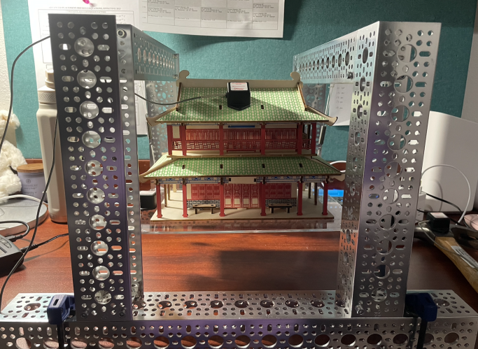
Figure 11. Test rig for the free-suspended building model.
For both models, a consistent pattern emerges with the presence of two distinct peaks: one in proximity to 1.5 Hz and the other closely situated around 30 Hz. The interpretation of these peaks unveils valuable insights into the structural dynamics. The first peak is likely linked to the rigid body mode of the test configuration, indicative of its overall motion as a single unit. On the other hand, the second mode aligns more closely with the building's bending mode. This bending mode assumes particular significance in practical scenarios, as it has the potential to induce elevated strain levels, thereby culminating in heightened stress concentrations at critical points within the structure. In this context, the investigation of the bending mode assumes importance due to its implications for the structural integrity and performance of the building under dynamic loading conditions. In the case of the mortise-tenon model, the predominant peak is observed within the frequency range of 22.5 Hz to 34.2 Hz. Conversely, for the glued model, this peak emerges between 39 Hz and 43 Hz. Upon closer examination of the second peak of the blue curve depicted in Figure 12, the nonlinearity of the peaks becomes evident, attributable to the presence of frictional damping. The identified damping ratio of two configuration can be seen in Table 2.
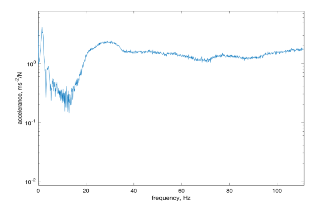
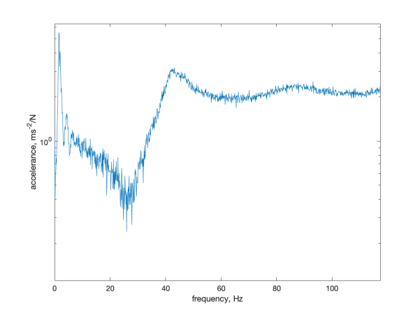
Figure 12. FRF graphs for flexible (left) and glued (right) models in free-free condition.
Table 2. Damping results under the free-free condition.
Fraction of the critical damping | |
Mortise-tenon | 22.9% |
Glued | 6.9% |
5. Case Study: Landers Earthquake Simulation
The obtained Frequency Response Function (FRF) from previous evaluation enables the estimation of the structure's acceleration response when subjected to a designated earthquake excitation. This estimation procedure entails the multiplication of the FRF with the Fourier transform of the historical earthquake ground excitation time history. This approach facilitates the prediction of the structure's acceleration frequency response to the specific earthquake excitation (as visualized in Figure 13). This acceleration spectrum can be subsequently transformed into the time domain using the inverse Fourier transform. This simulation facilitates a direct comparison and comprehension of how mortise-tenon-joint buildings mitigate earthquake vibrations through the combined effects of frictional damping within joints and the properties of the materials involved.
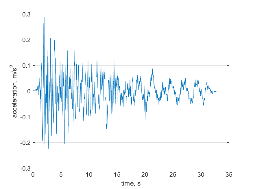
Figure 13. Historical earthquake excitation acceleration (Landers).
Figure 14 illustrates a comparative analysis of the acceleration response between mortise-tenon joint structures and glued counterparts, both subjected to the Landers earthquake excitation. The peak acceleration observed for the glued structure is 4.35 m/s², while the flexible structure records a peak acceleration of 3.87 m/s². This difference implies an 11.0% reduction in the mortise-tenon joint structure's acceleration due to the influence of frictional damping within joints and materials.
It is worth noting that this reduction rate might not appear substantial. This observation can be attributed to the resonance frequency of the bending mode in the building model, which exceeds 10 Hz. In contrast, real-world buildings typically exhibit resonance frequencies within the range of 0 to 10 Hz. As earthquake excitations predominantly occur at low frequencies, this mismatch between resonance and excitation leads to imperfect peak alignment, potentially contributing to the lower-than-expected reduction rate.
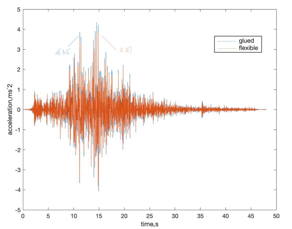
Figure 14. Simulated acceleration at roof when subject to excitation from Landers Earthquake.
6. Conclusions and Future Work
This study has successfully developed an economical sensor system tailored for high school students, employing accelerometers in conjunction with the LabQuest data acquisition tool. This innovative system equips students with the ability to systematically analyze structural responses to earthquake-induced vibrations. By facilitating the exploration of acceleration and vibration responses across a range of structural scenarios, this system empowers students to gain insights into strategies for bolstering damping efficacy and curtailing earthquake-related damage.
The key findings of this investigation underscore the seismic potential of mortise-tenon structures. Specifically, our results illuminate the capacity of such structures to attenuate earthquake vibrations, particularly in scenarios characterized by substantial relative displacement at the base. This advantageous behavior can be attributed to the pronounced frictional damping exhibited within the joints of mortise-tenon structures.
Looking ahead, this research lays the foundation for future inquiries. Subsequent investigations could focus on refining the design and construction of mortise-tenon structures to enhance their seismic resistance further. Moreover, by encompassing a wider range of structural forms and materials, future studies can contribute to a more comprehensive understanding of how various configurations respond to seismic events. This research trajectory also opens doors for ongoing educational initiatives, fostering increased engagement among students with earthquake engineering concepts and nurturing a deeper appreciation for structural dynamics and seismic performance.
References
[1]. Awen. (2019, March). The secrets for forbidden city to surviving earthquakes. https://www.viewofchina.com/chinese-building-structure.
[2]. Pan, L., Zhou, M., Zhuang, H., & Wang, J. (2022). Construction Forms and Seismic Performance of the Ancient Chinese Buildings Joined by Tenon–Mortise Joints. Applied Sciences, 12(15), 7505.
[3]. Lydia. (2021, March). How did China's forbidden city survive a magnitude 10 earthquake? Tellmechina. https://www.tellmechina.com/how-did-chinas-forbidden-city-survive-a-magni-tude-10earthquake.html#:~:text=On%20July%2028%2C%201976%2C%20the,from%20 the%20epicenter%2C%20was%20rocked.
[4]. Damping cross-reference. (n.d.). https://cdm.ing.unimo.it/dokuwiki/_media/wikipaom2017/ damping_cross-reference_and_material_properties.pdf
[5]. Mengjie. (2017, August 3). Chinese wisdom hidden in Forbidden City reverberates 600 years later in the modern world. Xinghuanet. http://www.xinhuanet.com//english/2017-08/03/c_136495692.htm#:~:text=In%20its%20600%20years%20of,7.8%20on%20the%20Richter%20scale.
[6]. Min, K.-W., Kim, J., Park, S.-A., & Park, C.-S. (2013). Ambient vibration testing for story stiffness estimation of a heritage timber building. The Scientific World Journal, 13.
Cite this article
Yang,A. (2023). Earthquake wonders: High school investigation in mortise tenon structures. Theoretical and Natural Science,9,62-72.
Data availability
The datasets used and/or analyzed during the current study will be available from the authors upon reasonable request.
Disclaimer/Publisher's Note
The statements, opinions and data contained in all publications are solely those of the individual author(s) and contributor(s) and not of EWA Publishing and/or the editor(s). EWA Publishing and/or the editor(s) disclaim responsibility for any injury to people or property resulting from any ideas, methods, instructions or products referred to in the content.
About volume
Volume title: Proceedings of the 3rd International Conference on Computing Innovation and Applied Physics
© 2024 by the author(s). Licensee EWA Publishing, Oxford, UK. This article is an open access article distributed under the terms and
conditions of the Creative Commons Attribution (CC BY) license. Authors who
publish this series agree to the following terms:
1. Authors retain copyright and grant the series right of first publication with the work simultaneously licensed under a Creative Commons
Attribution License that allows others to share the work with an acknowledgment of the work's authorship and initial publication in this
series.
2. Authors are able to enter into separate, additional contractual arrangements for the non-exclusive distribution of the series's published
version of the work (e.g., post it to an institutional repository or publish it in a book), with an acknowledgment of its initial
publication in this series.
3. Authors are permitted and encouraged to post their work online (e.g., in institutional repositories or on their website) prior to and
during the submission process, as it can lead to productive exchanges, as well as earlier and greater citation of published work (See
Open access policy for details).
References
[1]. Awen. (2019, March). The secrets for forbidden city to surviving earthquakes. https://www.viewofchina.com/chinese-building-structure.
[2]. Pan, L., Zhou, M., Zhuang, H., & Wang, J. (2022). Construction Forms and Seismic Performance of the Ancient Chinese Buildings Joined by Tenon–Mortise Joints. Applied Sciences, 12(15), 7505.
[3]. Lydia. (2021, March). How did China's forbidden city survive a magnitude 10 earthquake? Tellmechina. https://www.tellmechina.com/how-did-chinas-forbidden-city-survive-a-magni-tude-10earthquake.html#:~:text=On%20July%2028%2C%201976%2C%20the,from%20 the%20epicenter%2C%20was%20rocked.
[4]. Damping cross-reference. (n.d.). https://cdm.ing.unimo.it/dokuwiki/_media/wikipaom2017/ damping_cross-reference_and_material_properties.pdf
[5]. Mengjie. (2017, August 3). Chinese wisdom hidden in Forbidden City reverberates 600 years later in the modern world. Xinghuanet. http://www.xinhuanet.com//english/2017-08/03/c_136495692.htm#:~:text=In%20its%20600%20years%20of,7.8%20on%20the%20Richter%20scale.
[6]. Min, K.-W., Kim, J., Park, S.-A., & Park, C.-S. (2013). Ambient vibration testing for story stiffness estimation of a heritage timber building. The Scientific World Journal, 13.