


1. Introduction
A sweep wing is a design form of the aircraft wing, which is characterized by the main wing line of the wing and the longitudinal axis of the fuselage tilted at a certain angle. Swept-back wings can be traced back to the 1930s and were first proposed by German engineers. After World War II many jetliners and fighters began to use swept-back wings. After the 1970s, with the demand for supersonic flight, variable sweep aircraft gradually emerged, such as MiG-23.
The sweep angle is the angle at which the wing leans back from the wing root to the length of the wing tip relative to its average aerodynamic chord. Sweep angle is a key wing factor that affects the flight performance of aircraft.
Most of the published experimental data and literature are obtained through simulation. Sheng Zihao, Fan Geng & Hantian, computational fluid dynamics (CFD) simulation method is used, based on the Mach number range of 0.4 to 0.8, and the sweep angle of 15 to 45 degrees in the middle of the fourth-degree polynomial model [1]. Huang Z F, Lu X Z & Yu G C, stability analysis and transition prediction of sweep angle 25 degrees are performed by solving classical O-S equation (LST), extended O-S equation (EOS) and linear throw stability equation (LPSE) [2]. Lifang ZENG, Liu LIU, Xueming SHAO, Jun LI, a numerical simulation method combined with a structured moving offset grid is used to solve the fluid [3]. Lance W. Traub, Samarth M. Chandrashekar, wind tunnel model tests are built to replicate sweep angles of 0,45 and 60 degrees, and it is discovered that aerodynamic characteristics have a substantial influence on the cosine of the leading-edge sweep angle and the square root of the flap height [4]. Based on the available reference materials and experimental data, this paper studies and discusses the effects of different sweep angles on the performance of aircraft, such as lift, drag and lift-drag ratio, and verifies the corresponding cases. In this paper, the influence of different sweep angles on aircraft aerodynamic performance is studied in combination with the attitude from low-speed flight to supersonic flight, providing analysis for the design and research in the field of aviation engineering. In the future, researchers studying related research topics can take different sweep angles as a variable to further explore the influence of other parameters on aerodynamic performance.
2. Influence of swept wing angle on aerodynamics
2.1. Influence of different angles on lift
The factors affecting the lift of the aircraft mainly include angle of attack, wing shape, wingspan, etc. The experimental data are controlled as much as possible to simulate the comparison.
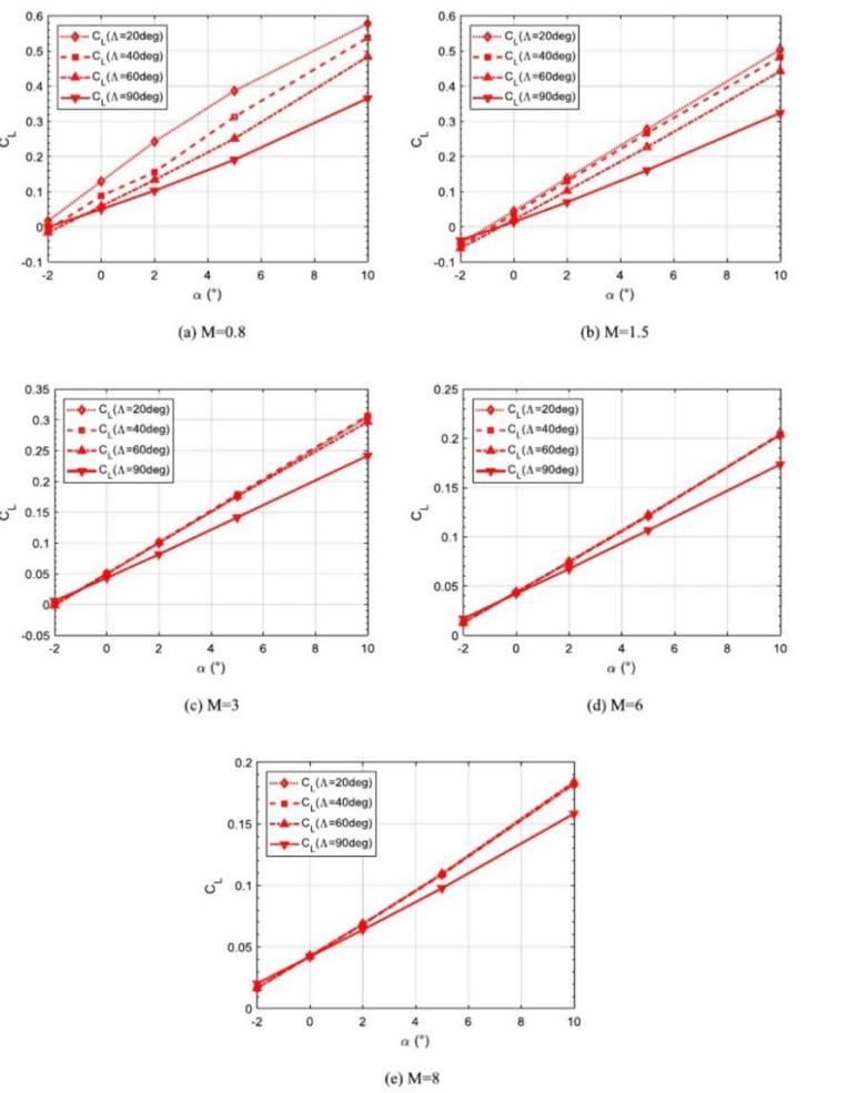
Figure 1. Lift coefficient of the variable-sweep-wing in different Mach number [5].
Pei Dai, Binbin Yan et al., calculated by uiel Goldberg using CFD++ code to obtain figure 1 lift coefficient diagram [5, 6]. \( α \) denotes the angle of attack, \( {C_{L}} \) denotes the lift coefficient, \( Λ \) denotes the sweep angle. It can be found from the data in the figure that under the same Mach number and angle of attack, the lift coefficient of 20 degrees sweep angle is usually the largest, but with the increase of Mach number, the lift coefficient of sweep angle gradually approaches the same.
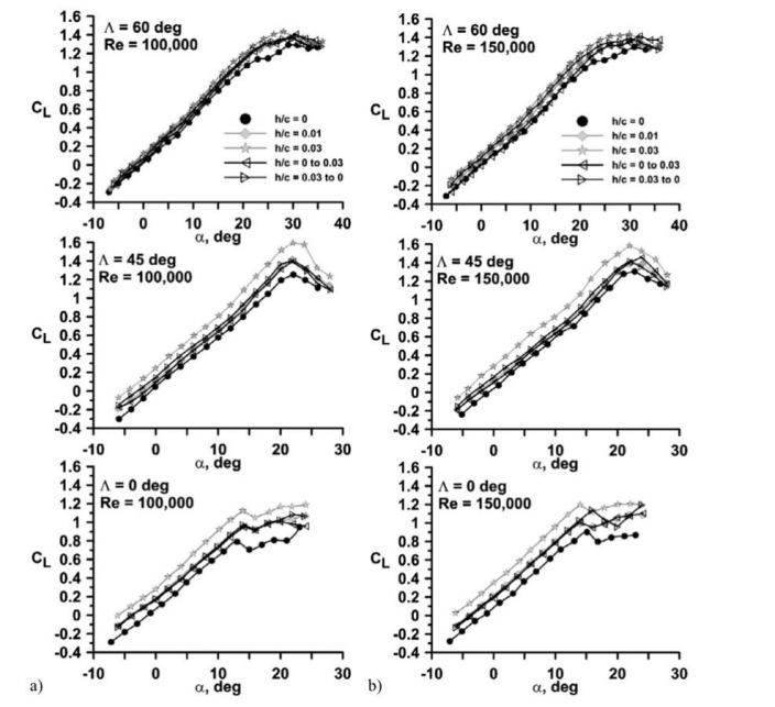
Figure 2. Effect of sweep and Gurney flap height on C L for Re = a) 100,000 and b) 150,000 [4].
Lance W. Traub and Samarth M. Chandrashekar simulated directly through wind tunnel experiments, although their research direction was the Effect of sweep and Gurney flap height, but by comparing the variation between different sweep angles, such as 0, 45 and 60 degrees, and the lift coefficient, some conclusions can also be drawn, figure2. Under the same attack angle and Reynolds number, the lift coefficients of 0 degree, 45 degree and 60 degree sweep angle decrease successively. It should be noted that the 0 degree sweep angle will have a significant downward trend of lift coefficient at 15 degrees of attack, while other sweep angles will appear at 20 degrees or even 30 degrees of attack. However, in the case of a suitable angle of attack, a small sweep angle will obtain a larger lift coefficient, which is more suitable for take-off and landing or low-speed flight.
However, due to the lack of data of 0-45 degree sweep angle, this paper referred to the CFD simulation data of Sheng Zihao, Fan Geng & Hantian et al.
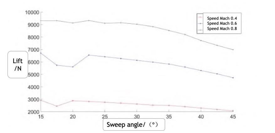
Figure 3. The relationship between lift and different sweep angles [1].
In Figure 3, the lift force in this set of data fluctuates between 15 and 25 degrees, and then tends to decline steadily. This conclusion is the same as the previous data when the sweep angle is larger, but there is a difference when the angle is smaller. In addition, all three sets of data show that the lift increases when the Mach number increases.
2.2. Influence of different angles on drag
In addition to lift, drag also needs to be considered, especially at high speed flight attitude, due to the presence of shock waves, air resistance can become hard.
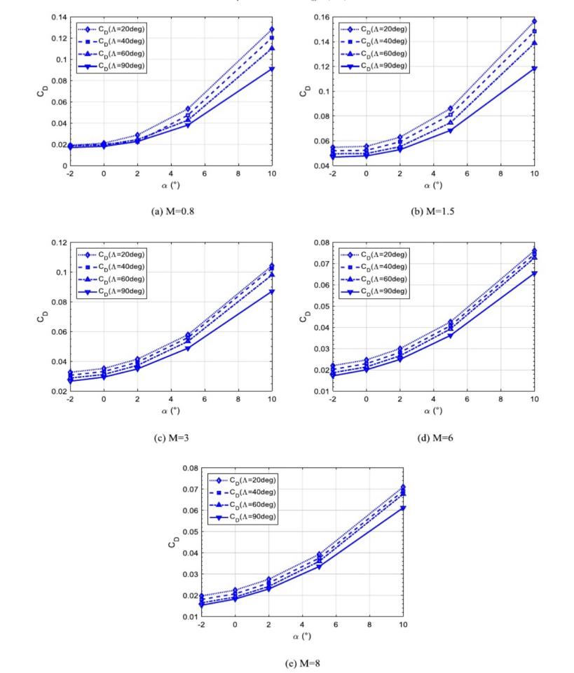
Figure 4. Drag coefficient of the variable-sweep-wing in different Mach number [5].
As can be seen from Figure 4, with the same Mach and angle of attack, the drag coefficient decreases continuously as the sweep angle from 20 degrees increases. Especially at supersonic flight attitude (Mach 0.8 to 1.5), there is a large difference in drag coefficient between sweep angle of 20 degrees and sweep angle of 60 degrees, but at hypersonic speed (Mach 6 to 8), the difference in sweep angle has no significant effect on drag coefficient. Next consider the drag of sweep angle at speeds Mach 0.4.
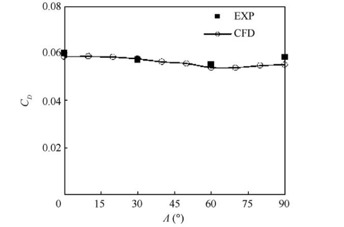
Figure 5. Different sweep angles (Ma = 0.4, a = 4) [3].
The data shown in Figure 5 were obtained by Lifang ZENG, Liu LIU, Xueming SHAO and Jun LI through CFD simulation and experimental simulation. When the Mach number is 0.4 and the angle of attack is 4 degrees, the influence of sweep angle on the drag coefficient seems to be less than expected. When the sweep angle is 60 degrees, the drag coefficient reaches the minimum value, and then there is a trend of increasing.
Although the Mach number of the two groups of experiments is different, there are some contradictions in the influence of sweep angle on the resistance after 60 degrees, the resistance of the former continues to decrease, while the resistance of the latter has a rising trend. The possible reason is that when the speed reaches Mach 0.8, the leading edge of the wing will generate shock waves, and it will accumulate with the increase of speed, and the backward swept wing just slows down the formation of shock waves, so that the drag is reduced. Therefore, when flying at low speed (Mach number less than 0.8), the impact of sweep angle on drag is not significant, while when flying at supersonic speed (Mach number greater than 0.8), due to the presence of shock waves, the larger the sweep angle, the smaller the drag generated.
2.3. Influence of different angles on lift drag ratio
Lift-drag ratio is used to measure the proportional relationship between lift and drag of an aircraft. The higher the value, the better the performance of the aircraft, because it can generate more lift with less resistance.
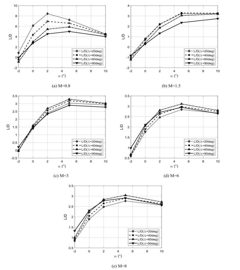
Figure 6. Lift-to-drag ratios of the variable-sweep-wing in different Mach number [5].
Lift-drag ratio is used to measure the proportional relationship between lift and drag of an aircraft. The higher the value, the better the performance of the aircraft, because it can generate more lift with less resistance. General aircraft wing angle of attack is 5 to 10 degrees, so when the angle of attack is unified to 6 degrees, when the Mach number gradually increases from 0.8, the greater the sweep angle, the greater the resulting lift-drag ratio [7]. When breaking the speed of sound, the swept-back wing angle that produces the maximum lift-drag ratio is between 20 and 40 degrees.
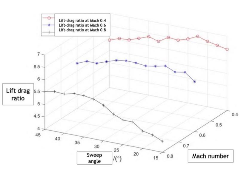
Figure 7. Lift-drag ratio of variable-sweep wing aircraft [1].
The data in Figure 7 illustrates how the lift-drag ratio between Mach 0.4 and 0.8 is affected by various sweep angles. a CFD-based, three-dimensional data model from the Journal of Naval Aeronautical University [1]. The sweep angle, the Mach number, and the lift drag ratio are represented by the X, Y, and Z axes, respectively.
When the Mach number is 0.4 and 0.6, the lift drag ratio of sweep angle is maximum at about 25 degrees, and when the Mach number is 0.8, the lift drag ratio is maximum at 45 degrees. At Mach 0.4 and 0.6, the relationship between sweep angle and lift-drag ratio is not significant and fluctuates up and down, while at Mach 0.8, lift-drag ratio increases with the increase of sweep angle, which is the same as the simulation results of the previous group.
3. Application of swept-back wing on different aircraft
3.1. Civil aircraft
The Boeing 737 family must be included if people wish to discuss the most successful and frequently used civilian aircraft. The maiden flight of this short-to-medium-range narrow-body aircraft occurred in 1968. 62 tons of maximum gross takeoff weight and a wingspan of 28.45 meters. The Boeing 737's swept-wing angle is designed to be a quarter-string sweep of 25°. Designing at this angle necessitates various considerations. First of all, with a high-altitude cruising speed of 828 km/h and a Mach 0.67 speed, which is the speed at which most airplanes fly, it does not need especially strong maneuverability for a commercial airliner. According to the data analysis above, engineers created a sweep angle of 25 degrees for this spot, and this angle also has a favorable lift-drag ratio and lift. In addition, the takeoff and landing of the aircraft are also crucial, the smaller the sweep angle, the greater the lift, in the case of prioritization of cruise speed, 25 degrees of sweep angle can provide a better lift coefficient for the passenger jet [8]. Finally, in terms of energy efficiency, the 25-degree swept-back wing does not bring much drag, improving the energy efficiency of the flight and increasing the economic effect, which is important for commercial flight. Of course, the success of the Boeing 737 cannot be fully attributed to the 25-degree swept-back wing, but its role is beyond doubt, and it is undoubtedly helpful and useful for the development of passenger aircraft.
3.2. Military aircraft
For fighters, it is not like passenger aircraft, fighters need to pursue extreme aerodynamic, and different sweep angles will have different effects, so variable sweep wings are produced to meet different situations, such as MIG-23.
The MIG-23 is a fighter aircraft designed and built by the former Soviet Union and officially unveiled in 1967. The MIG-23 has a maximum speed of about 2,445 km/h or Mach 2.35 (supersonic speed) and a combat radius of about 600 to 1000 km. The MIG-23 uses variable swept wing technology so that its swept wing can be adjusted into three sweep angles, respectively 18, 47 and 74 degrees, because it needs to account for both low speed and supersonic flight [9].
In light of the statistics on sweep angle presented above, an 18-degree sweep angle with a high lift-drag ratio is appropriate for aircraft takeoff and landing. Large lift coefficients, though, can also significantly shorten the runway's takeoff distance. Additionally, a 47-degree sweep angle balances the performance of high- and low-speed flights. It is suitable for aerial warfare and maneuvering flight because it can retain a streamlined shape within a given range and has strong stall characteristics and a high lift coefficient. Last but not least, a 74-degree sweep can lower drag because shock waves that originate over the swept wing pass over the airfoil at a larger angle, minimizing turbulence losses, which helps the MIG-23 fly at supersonic speeds (Mach 2.35).
The variable sweep wing ensures that the MIG-23 provides flexibility and superior flight performance in different flight phases, ensuring reliability for multi-purpose missions. Although the MIG-23 is now retired and has been replaced by new models, it has important reference value in air Force history.
4. Conclusion
In this paper, the effects of different sweep angles on lift, drag and lift-drag ratio of aircraft at different Mach numbers are studied. Through the study and analysis of previous simulation data and real aircraft cases, a smaller sweep angle (about 20 degrees) can lead to a better lift-drag ratio for aircraft take-off and landing. The larger sweep angle can bring better aerodynamic performance, which is suitable for supersonic flight and reduces the drag caused by shock waves. Moderate sweep angle for better manoeuvrability and stability. In this paper, the balance between an aircraft's maneuverability and stability at various sweep angles is discussed. Future studies can examine the aircraft's stability and maneuverability in more detail. Future researchers might further investigate the impact of other aerodynamic characteristics on aircraft performance, such as airfoil, Angle of attack, etc., based on the investigation of various sweep angles in this paper.
References
[1]. Sheng Zihao, Fan Geng & Hantian. (2022). Optimal sweep Angle prediction model of variable sweep wing with single velocity based on CFD. Journal of Naval Aeronautical University (01),153-158.
[2]. Huang Z F, Lu X Z & Yu G C. (2014). Crossflow stability analysis and transition prediction of wing boundary layer. Journal of Aerodynamics (01),14-20.
[3]. Lifang ZENG, Liu LIU, Xueming SHAO, Jun LI. (2023) Mechanism analysis of hysteretic aerodynamic characteristics on variable-sweep wings. Chinese Journal of Aeronautics, 212-222.
[4]. Lance W. Traub, Samarth M. Chandrashekar. (2016) Experimental study on the effects of wing sweep on Gurney flap performance, Aerospace Science and Technology, Pages 57-63, ISSN 1270-9638.
[5]. Pei Dai, Binbin Yan, Wei Huang, Yifei Zhen, Mingang Wang, Shuangxi Liu. (2020) Design and aerodynamic performance analysis of a variable-sweep-wing morphing waverider, Aerospace Science and Technology, 105703, ISSN 1270-9638.
[6]. U. Goldberg, (2005) Hypersonic turbulent flow predictions using CFD++, in: AIAA/CIRA 13th International Space Planes and Hypersonics Systems and Technologies Conference
[7]. Li Aijun, Shen Yi, Zhang Weiguo.(2002). A fuzzy control method for high elevation flight of aircraft. Aircraft Design (04),42-44. doi:10.19555/j.cnki.1673-4599
[8]. Zuo Yuhan, Yang Yong, Li Dong, et al. (2010) Experimental study on the cross-flow instability of swept-back wing Boundary Layer [J]. Journal of Aerodynamics,28 (5):495-502.
[9]. Wang F C. (1994). Review of design characteristics of MIG-23 aircraft. Aircraft Design (02),72-80. doi:10.19555/j.cnki.1673-4599.1994.02.014.
Cite this article
Chen,K. (2023). The performance and application of sweep wing aircraft. Theoretical and Natural Science,9,73-80.
Data availability
The datasets used and/or analyzed during the current study will be available from the authors upon reasonable request.
Disclaimer/Publisher's Note
The statements, opinions and data contained in all publications are solely those of the individual author(s) and contributor(s) and not of EWA Publishing and/or the editor(s). EWA Publishing and/or the editor(s) disclaim responsibility for any injury to people or property resulting from any ideas, methods, instructions or products referred to in the content.
About volume
Volume title: Proceedings of the 3rd International Conference on Computing Innovation and Applied Physics
© 2024 by the author(s). Licensee EWA Publishing, Oxford, UK. This article is an open access article distributed under the terms and
conditions of the Creative Commons Attribution (CC BY) license. Authors who
publish this series agree to the following terms:
1. Authors retain copyright and grant the series right of first publication with the work simultaneously licensed under a Creative Commons
Attribution License that allows others to share the work with an acknowledgment of the work's authorship and initial publication in this
series.
2. Authors are able to enter into separate, additional contractual arrangements for the non-exclusive distribution of the series's published
version of the work (e.g., post it to an institutional repository or publish it in a book), with an acknowledgment of its initial
publication in this series.
3. Authors are permitted and encouraged to post their work online (e.g., in institutional repositories or on their website) prior to and
during the submission process, as it can lead to productive exchanges, as well as earlier and greater citation of published work (See
Open access policy for details).
References
[1]. Sheng Zihao, Fan Geng & Hantian. (2022). Optimal sweep Angle prediction model of variable sweep wing with single velocity based on CFD. Journal of Naval Aeronautical University (01),153-158.
[2]. Huang Z F, Lu X Z & Yu G C. (2014). Crossflow stability analysis and transition prediction of wing boundary layer. Journal of Aerodynamics (01),14-20.
[3]. Lifang ZENG, Liu LIU, Xueming SHAO, Jun LI. (2023) Mechanism analysis of hysteretic aerodynamic characteristics on variable-sweep wings. Chinese Journal of Aeronautics, 212-222.
[4]. Lance W. Traub, Samarth M. Chandrashekar. (2016) Experimental study on the effects of wing sweep on Gurney flap performance, Aerospace Science and Technology, Pages 57-63, ISSN 1270-9638.
[5]. Pei Dai, Binbin Yan, Wei Huang, Yifei Zhen, Mingang Wang, Shuangxi Liu. (2020) Design and aerodynamic performance analysis of a variable-sweep-wing morphing waverider, Aerospace Science and Technology, 105703, ISSN 1270-9638.
[6]. U. Goldberg, (2005) Hypersonic turbulent flow predictions using CFD++, in: AIAA/CIRA 13th International Space Planes and Hypersonics Systems and Technologies Conference
[7]. Li Aijun, Shen Yi, Zhang Weiguo.(2002). A fuzzy control method for high elevation flight of aircraft. Aircraft Design (04),42-44. doi:10.19555/j.cnki.1673-4599
[8]. Zuo Yuhan, Yang Yong, Li Dong, et al. (2010) Experimental study on the cross-flow instability of swept-back wing Boundary Layer [J]. Journal of Aerodynamics,28 (5):495-502.
[9]. Wang F C. (1994). Review of design characteristics of MIG-23 aircraft. Aircraft Design (02),72-80. doi:10.19555/j.cnki.1673-4599.1994.02.014.