


1. Introduction
A jet engine is a sort of heat engine or electric motor that propels and expels high-velocity fluid to carry out work. It is able to provide both shaft power and thrust. Although there are few exceptions, internal combustion engines, such as most jet engines, operate according to Newton's third law. Turbofan, turbojet, rocket, ramjet, and pulse-press jet engines are examples of common jet engines. The invention of the jet engine dates back to the thirteenth century. China at the time utilized it for rudimentary rockets and pyrotechnics. In late WWII, The jet engine was used in Me-262 by Nazi Germany, wish to stop the air strike from Allied. Even though it cannot turn the tide of battle, it shows the possibility of jet engines used on aircraft. Also, the V1 rocket gave a clear path for the guided missile to become one of the main weapons in modern war. Until now, jet engines are still the most commonly used on aircraft, both in civilian and military. As material and design improvement improves, jet engines become better and stronger than ever [1-3].
In order to improve the whole jet, there are already lots of different actions to improve the jet engine. For example, the DSI is put on the fighter jet plane to allow the gas to maintain a constant velocity and stable pressure while it enters the combust chamber. After that, some useful improvement suggestions would be provided, and hopes in the future will help to improve the jet engine. The article will introduce and analyze the current state of aviation pollution emissions, examine the mechanisms behind generating aviation pollutants, discuss the mainstream methods for emission reduction currently in use, and finally, provide predictions on the future development trends of emission reduction in civil aviation.
2. The fundamentals of jet engine
Air intake at stage 1 goes through the low-pressure compressor, stage 2 and then passes through stage 3, a high-pressure compressor. There are many small blades on the compressor. These blades can slow down the airflow and increase the pressure. The purpose is to make the air denser and increase the temperature and pressure of it to the point where it is suitable for continuous combustion. Then the squeezed air will go through the combustion chamber, which is stage 4. The fuel injector will inject the atomized fuel, which can mix with squeezed air, and the mixture will be set on fire. The mixture will expand in a short time and be ejected out of the nozzle in a high-speed and high-temperature state to form a jet flow. The jet flow will spin the turbine behind the combustor, which is connected to the compressor by a shaft, which means the jet flow drives the compressor.
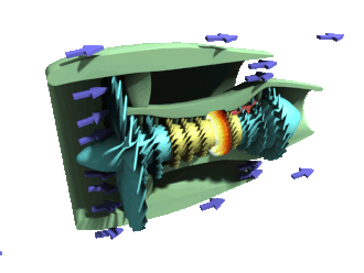
Figure 1. Scheme of turbofan, reproduced from the website: https://en.wikipedia.org/wiki/Turbofan.
The turbofan engine works similarly to the turbojet engine, as shown in Figure 1. The difference is that there is a big fan in front of the turbofan engine and a low-pressure turbine behind the combustion chamber. The low-pressure chamber initiatives the fan, and the high-pressure chamber energies the compressor. The air is sucked in by the big fan and separated into the inner channel (red arrow) and the outer channel (blue arrow). The air passing through the outer channel will be accelerated to achieve a higher reverse thrust.
3. The recent progress of the jet engine
The DIS is the first of many recent advancements made to the jet engine. The Advanced Propulsion Integration project, an autonomous research and development endeavor, was where Lockheed Martin engineers first began the work that would become the DSI. The design was designed and enhanced using exclusive computer modeling methods pioneered by Lockheed Martin and made possible by advancements in computational fluid dynamics (CFD) [3]. Recent studies revealed that the DSI delivered the necessary mass flow and stable pressure compression ratio with satisfactory properties in stable working settings. Additionally, the DSI performance curve clearly show a substantially distinct behavior, particularly in supercritical conditions. CFD, which is regarded as a subfield of fluid dynamics, offers an affordable way to simulate airflow. CFD has advanced thanks to the creation of more potent computers to the point that it is now the go-to method for assessing aerodynamic designs [4-6].
New ways to build the turbofan blade were used on jet engines. One of them is the Solidification crystallization control technology. This refers to a casting process in which the molten alloy crystallizes and solidifies in the investment casting shell in the direction opposite to the heat flow. Turbine blades formed by this process are highly resistant to thermal fatigue and thermal shock. Nowadays, many new directional solidification technologies that combine the advantages of traditional technology and the latest technology are emerging, including regional melting liquid metal cooling method, electromagnetic constrained forming directional solidification method, deep subcooling directional solidification method, laser ultra-high temperature gradient rapid solidification technology and continuous directional solidification technology [3, 7].
4. Some future possibilities to improve the jet engine
In the sub-sonic flight, we would choose the turbofan engine with a high bypass ratio to increase fuel efficiency. This indeed allows a plane to stay longer in the sky while flying further. However, this can be a disadvantage in the supersonic situation. A higher bypass ratio brings higher wind resistance, which becomes critical in supersonic speed. Allowing the engine itself to control the bypass ratio may be a useful design. An auto-shrinking device would be able to close the most bypass part. This might reduce air resistance during supersonic flight [8-10].
The material was another way to improve the jet engine. Inside the combust chamber, every time it works, it brings extreme heat with high pressure across the fan blade behind it. Under this extreme environment, the blade and combust usually don’t have a long-lasting service. As a way to improve the service life, choosing special material can be one of the options. Niobium silicide composite materials have good oxidation resistance, insect resistance, acceptable fracture toughness, fatigue resistance, high-temperature strength, impact resistance, and castability. Ceramic matrix composites. Even on a density-normalized basis, their strength is relatively low. Good shock resistance and stability at high operating temperatures make this system attractive for a well-designed system [4, 11].
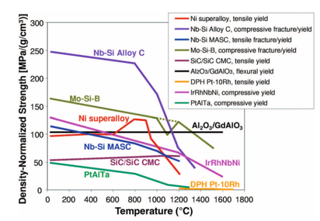
Figure 2. Strength of ultrahigh-temperature materials for jet engines [5].
However, this is not enough. Even though the material can handle the heat and is strong enough to handle the process, further improvement was needed. One process to solve that was adding a thermal coat to block the heat and fuel from directly contacting the chamber wall and fan blade. A thermal barrier coating (TBC) usually consists of a tie coat and a topcoat. MCrAlY (M: nickel, cobalt, or a mixture of both elements) and heat-resistant materials, such as yttria-stabilized zirconia (8YSZ), are the most commonly used materials for the bond and top layers, respectively.
The most often utilized bond coat components are Ni, Co, Cr, Al, Ta, Si, Hf, Y, Y2O3, and Pt. The bond coat is mostly metallic. Interdiffusion between the bond coat and the substrate, the microstructure and morphology of thermally generated oxides (TGO), and phase transition-induced cracking all have an impact on the bond coat's resistance to oxidation. The two bond coatings that are most frequently applied to a TBC are MCrAlY (M=Ni/Co, NiCo) and platinum-doped aluminides. A metal oxide interface is created when oxidizing species or the atoms of a metal spread inward or outward, respectively. At higher operating temperatures, metals don't produce a distinct oxide layer; instead, they form subsurface precipitates. The strains are anticipated to be caused by the formation of oxide. The stresses are expected to generate due to the oxide formation as the oxide volume differs from the consumed metal. Thermal spraying techniques deposit the bonding and top layers on the metal substrate. TBC also needs to deal with the stress fracture. The break of TBC might not damage the fan blade directly; it did expose the material to the burning zone and high-temperature jet stream mix with underburned fuel [5]. Since the fuel is still burning, the fan blade would suffer irreparable damage from heat corrosion to the material. Destructive testing methods that rely on the strain produced as a result of material removal are required to assist overcome this issue. With the hole drilling (HD) and layer removal (LR) techniques, released strain is measured with a strain gauge fastened to the coating or the substrate after each consecutive cut.
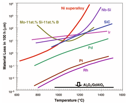
Figure 3. Material loss of the investigated materials [5].
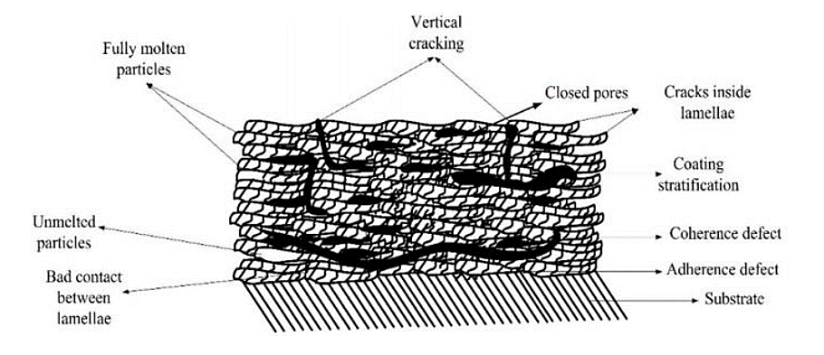
Figure 4. Thermal barrier coatings [7].
5. Conclusions
The jet engines were pushed to the edge by recent development. From the first long rage rock(missile) to the modern jumbo jet, jet engines became the widest used engine in airplanes. As time passed, the jet engine didn’t stop the development. The DSI was able to stable the airflow and its pressure to support the jet engine in both subsonic and supersonic. This allows the modern jet fighter plane to reduce the weight in the device used to control the inlet size, a huge improvement in saving weight on airplanes. Different materials, such as CMC, were used, suitable for high-temperature working environments. Above that, a thermal coat was used to block the material from the burning environment to protect the fan blade from heat erosion and extremely high temperatures. This gives the fan blade a longer service life while becoming more stable. In the future, the jet engine will still maintain its leading position. On earth, in space travel, jet engines would still be one of the major engines in spacecraft, allowing it to fly on other planets from one place to another. The potential of the jet engine was still inestimable, which valued people to pay more attention to its development.
References
[1]. Volponi A 2014 Journal of Engineering for Gas Turbines and Power 136 051201
[2]. Wang Y, Yang Z, Li P, Cao D, Huang W and Inman D 2020 Nano Energy 75 104853
[3]. Soltani M and Askari R 2019 Aerospace Science and Technology 91 538
[4]. Nagy Z 2017 Engineering Crystallography: From Molecule to Crystal to Functional Form 289
[5]. Zhao J and Westbrook J 2003 MRS Bulletin 28 622
[6]. Thakare J, Pandey C, Mahapatra M and Mulik R 2021 Metals and Materials International 27 1947
[7]. Zhao J 2008 Journal of Aerodynamics 6 986
[8]. Zou J and Yan Y 2021 Civil Aircraft Design and Research 4 90
[9]. Zhan T and Deng Z 2019 Science and Technology Innovation and Application 2 151
[10]. Zhang Y 2021 Key technologies and challenges of hydrogen aviation Aerospace Power 1 20
[11]. Li J and Ju Y 2013 Advanced low-emission single-ring combustion chamber at Honeywell Aeronautical Science and Technology 6 31
Cite this article
Zhang,J. (2023). Resolving puzzles in jet engines from history and future. Theoretical and Natural Science,9,81-85.
Data availability
The datasets used and/or analyzed during the current study will be available from the authors upon reasonable request.
Disclaimer/Publisher's Note
The statements, opinions and data contained in all publications are solely those of the individual author(s) and contributor(s) and not of EWA Publishing and/or the editor(s). EWA Publishing and/or the editor(s) disclaim responsibility for any injury to people or property resulting from any ideas, methods, instructions or products referred to in the content.
About volume
Volume title: Proceedings of the 3rd International Conference on Computing Innovation and Applied Physics
© 2024 by the author(s). Licensee EWA Publishing, Oxford, UK. This article is an open access article distributed under the terms and
conditions of the Creative Commons Attribution (CC BY) license. Authors who
publish this series agree to the following terms:
1. Authors retain copyright and grant the series right of first publication with the work simultaneously licensed under a Creative Commons
Attribution License that allows others to share the work with an acknowledgment of the work's authorship and initial publication in this
series.
2. Authors are able to enter into separate, additional contractual arrangements for the non-exclusive distribution of the series's published
version of the work (e.g., post it to an institutional repository or publish it in a book), with an acknowledgment of its initial
publication in this series.
3. Authors are permitted and encouraged to post their work online (e.g., in institutional repositories or on their website) prior to and
during the submission process, as it can lead to productive exchanges, as well as earlier and greater citation of published work (See
Open access policy for details).
References
[1]. Volponi A 2014 Journal of Engineering for Gas Turbines and Power 136 051201
[2]. Wang Y, Yang Z, Li P, Cao D, Huang W and Inman D 2020 Nano Energy 75 104853
[3]. Soltani M and Askari R 2019 Aerospace Science and Technology 91 538
[4]. Nagy Z 2017 Engineering Crystallography: From Molecule to Crystal to Functional Form 289
[5]. Zhao J and Westbrook J 2003 MRS Bulletin 28 622
[6]. Thakare J, Pandey C, Mahapatra M and Mulik R 2021 Metals and Materials International 27 1947
[7]. Zhao J 2008 Journal of Aerodynamics 6 986
[8]. Zou J and Yan Y 2021 Civil Aircraft Design and Research 4 90
[9]. Zhan T and Deng Z 2019 Science and Technology Innovation and Application 2 151
[10]. Zhang Y 2021 Key technologies and challenges of hydrogen aviation Aerospace Power 1 20
[11]. Li J and Ju Y 2013 Advanced low-emission single-ring combustion chamber at Honeywell Aeronautical Science and Technology 6 31