


1. Introduction
FSAE (Formula SAE) is one of the most popular races around the world. The racing car will face a variety of challenges. To prevent the racing car from sliding off the track when steering, the tires must provide enough friction. However, the friction force brought by the car’s weight is not enough. Then, people find another way to provide extra friction. It is common sense that friction is related to pressure. Therefore, engineers just need to develop a device which can increase the pressure of car to the ground. Aerodynamic packages come into sight. Aerodynamic performance has a greater impact on the overall performance of a racing car [1]. Generally, aerodynamic devices can provide about 1000N downforce at the speed of 20m/s. Front wing is the most important part of the packages. It not only provides 30% of downforce, but also has a huge impact on other parts, such as the rear wing and diffuser. For example, the airflow lifted by the front wing will reduce the downforce of the rear wing. Moreover, if the front wing is too close to the ground, the entrance of diffuser may be obstructed by the front wing. That means the diffuser cannot work properly. All evidence indicates that the aerodynamic package, especially front wing, is an essential part in race and closely affects the power, economy and stability of the car. The aerodynamic package can help the racing car steer at a high speed instead of slowing down. Though the engineers have made a lot of efforts, there are still problems to be solved. This article focuses on the front wing design and downforce improvement. Several designs from previous years are combined in order to modify the new design. This article works on improving downforce and controlling turbulence. By using CFD(computational fluid dynamics) software, this article analyzes the aerodynamic characteristics of a front wing and proposes many novel designs. The use of CFD enables a substantial reduction of test times and costs of new designs[2].
2. Rules and background for front wing
In FSAE, each participating team is supposed to develop and produce a compact single-seat car within one year in accordance with the rules formulated by the organizers. For front wing, it is also strictly limited by the rules:
(1). The front wing's clearance from the ground is 30 mm at the minimum and 500 mm at the maximum.
(2). The width of the front wing must not exceed the outermost part of the tire.
(3). There is a forbidden region, which is a square area around the tires. The width of this area is equal to the width of tires and its length is 75mm+the diameter of the tire+75mm. More specifically details are shown in Figure 1.
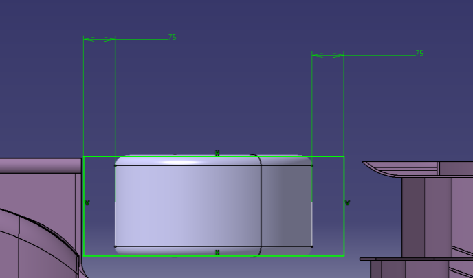
Figure 1. Off-limits area.
(4). The maximum distance between the foremost edge of front wing and the foremost edge of tire is 700mm.
Therefore, the design is supposed to not only make the lift force generated by the front wing as large as possible, but also take the rules into consideration. Moreover, the front wing will generate drag force as well, so the ratio of CL to CD called K is also important. Additionally, the most important influence of the reduction of drag is the increment in the car’s maximum speed[3]. The capability of the aerodynamic engineer is to compromise between down force and drag[4]. The front wing plays an essential role in air direction at the same time. There will be several high-pressure regions in front of the front wings. These high-pressure regions increase the adverse pressure gradient on the suction side of the wing[5]. A well-designed front wing must take all of them into account.
To balance the torques which generated by other aerodynamic packages, such as diffuser and rear wing, a practical purpose for the front wing is set as follow:
(1). The front wing must generate about 230N down force at the speed of 16.6m/s.
(2). The K (ratio of CL to CD) should be larger than 6.
(3). The front wing can direct turbulence away from the diffuser’s entrance.
3. Fundamental and settings of front wing design
The aerodynamics simulation is run on STAR CCM+. The physical model is 3D - constant density - segregated flow - realizable k-ε turbulence model. Turbulence is a chaotic and random state of motion in which the velocity and pressure change continuously with time within substantial regions of flow [6]. The realizable k- model differs from the standard k- model in that it includes a formulation for turbulent viscosity. A block is set as the fluid field, size of which is 8m×1.5m×1m. The block is divided into 4 parts: inlet, outlet, ground and walls. Inlet means where the airflow blows in, and the outlet is where the airflow blows out. The inlet is 1m in front of the foremost point of front wing while the outlet is 7m behind the last edge of front wing. That’s why the length of block is 8m. The initial fluid field conditions are uniform. The pressure is 1 atm and the velocity (inlet) is 20m/s. Dynamic viscosity is set at 2.0e-5 Pa·s and the density of air is 1.29kg/m3.
4. Lift-increasing devices on the front wing
In order to interpret the front wing more clearly, a coordinate system needs to be defined. The direction which is vertical to the front view is called x direction and the direction which is vertical to the side view is called y direction. The final direction is called z direction. The front wing is divided into 2 sections. One is the area 2 which acts as a guide for airflow away from the tire. Since the wheels contribute to 40% of the total car drag, it is essential to reduce it as much as possible [7]. The other is the area 1 which provides extra downforce and limits the effect of turbulence on the rear wing. The airfoil of the main wing is NACA6413 with an angle of -4°. Its length is 400mm. The airfoil of flaps is NACA4412, but the angle of attack and the length is quite different. A prototype of front wing is shown in Figure 2. In order to improve the aerodynamic characteristics, more devices need to be used in front wing.
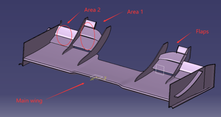
Figure 2. Front wing prototype.
4.1. Flaps of front wing
In general, the flaps will lead the airflow to blow up when it works. This turbulence always has a negative impact on rear wing. It will severely decline the down force generated by the rear wing, so it’s necessary to design a kind of flap to diminish this phenomenon. The flap near the inside is the main factor. Normally, the flap is a geometry stretched from an airfoil and the air always flows evenly across the surface. The flap can achieve the control of airflow. For example, if the airfoil of the left side is smaller than the right side’s, the model software will create a flap with curvature, as the flap shown in Figure 3.
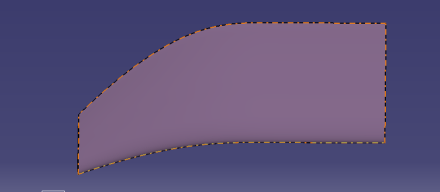
Figure 3. Special flap.
Due to the left side’s smaller size, the airflow will segregate from the trailing edge earlier than right side. That means the airflow near the inside will reach the rear wing much harder. However, the smaller size has side effects that the downforce of the flap will also decrease. To address the issue, an extra flap is placed at the slanting top of this special flap. The extra flap is shown in Figure 4.
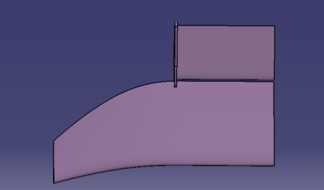
Figure 4. Extra flap.
4.2. Endplate
Due to the differing pressures on the upper and lower surfaces, the flow on the lower surface typically tends to flow through the side edge of the wing to the higher surface. The convergence of the two flows not only declines the downforce and increases the drag force, but also plays a negative role in airflow directing. An endplate can eliminate these passive flows. The downforce is improved markedly with an endplate. The function of the endplate does more than that. When banding the back part, the endplate will serve as an accelerate channel. When the endplate area is increased, the overall lift coefficient increases while there is a significant reduction in drag coefficient [8]. In this way, the flow on the lower surface will be accelerated to a faster speed than before. Bernoulli’s equation shows that the faster air blows, the larger down force it gains. The speed is the most effective factor in this circumstance. In addition, the endplate is able to direct the turbulence flow bypass the tire. This reduces the drag and helps the racing car work more efficiently. Furthermore, the small gadget under the endplate is called endplate foot. Its function is to generate a strong vortex which plays a critical role in preventing the low-energy airflow from coming into low pressure area. The Q-criterion of the endplate is displayed in Figure 5, which gives a more vivid interpretation of the endplate’s and endplate foot’s functions.
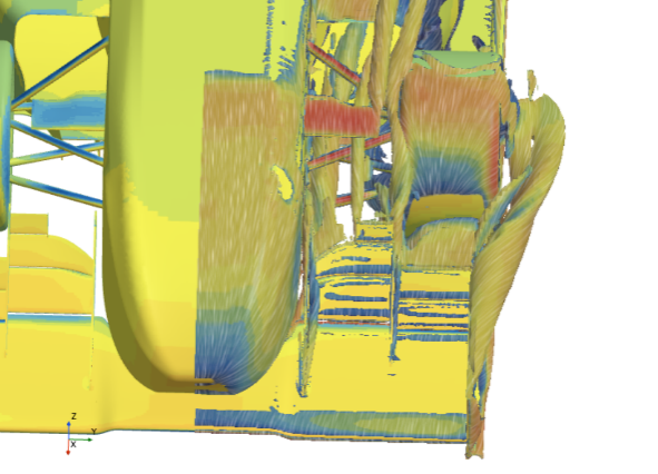
Figure 5. Q-criterion of endplate.
4.3. Wing fence
Considering that the diffuser needs air intake, some parts of the front wing need to be raised. What’s more, to prevent the front wing and the front of the car from interfering, the central part uses a 330mm long airfoil. Although this is a useful solution, it still remains some problems. The most serious issue is that the airflow tends to move in y direction due to some of the raised surface that is mentioned before. The air flowing in this direction loses energy. In other words, these kinds of airflow are of no use in generating lift. According to Kutta condition, if the air flow moves in y direction, the airflow on the upper surface and the airflow on the lower surface will not converge at the trailing age. Apparently, some devices need to be designed to prevent airflow from moving in unexpected direction. The wing fence is an ideal gadget. It works like a plate that obstructs span-wise airflow along the wing. It also prevents stalling while restoring downforce. Figure 6 and Figure 7 show the Q-criterion of the front wing with and without the wing fence. It’s obviously that the wing fence improves the airflow very well.
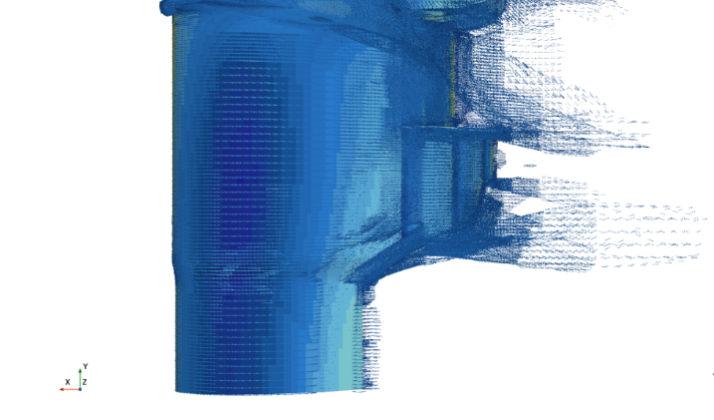
Figure 6. Front wing without wing fence.
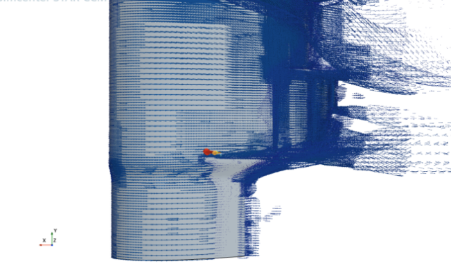
Figure 7. Front wing with wing fence.
4.4. Gurney flap
The central part of main plane uses relatively small size airfoil to be assembled with the car. However, the shortening of the airfoil causes that the available downforce is also reduced. A famous American racer uses a sophisticated device on flaps in a race. Gurney flaps are a simple addition mounted perpendicularly to a wing's pressure side along the trailing edge that increase the car's aerodynamics without requiring sophisticated structural support[9]. It helps to gain extra downforce in the race. The gurney flap obstructs the airflow on the upper surface. In this way, a lower pressure area is created on the upper surface compared to the front wing without gurney flaps. Gurney flap’s aerodynamic efficiency is quite considerable even it creates some drag at the same time. For this front wing, the gurney flap is placed at the area with small size airfoil to recover the downforce. The statistic demonstrates that this is a practical plan to solve the problem. The gurney flap is shown in Figure 8. Table 1 lists the downforce of the front wing with and without the gurney flap.
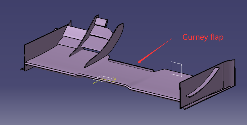
Figure 8. Gurney flap.
Table 1. Front wing with and without gurney flap.
Downforce | Drag | |
With gurney flap | 353.18N | 53.24N |
Without gurney flap | 326.96N | 51.68N |
5. Simulation of whole racing car
A well-designed front should not only focus on the individual part, the airflow behind the front wing is also important. The design of the aerodynamic package revolves around maximizing downforce, while keeping drag to minimum and keeping the center of pressure around the centre of the wheelbase[10]. Inappropriate vortex and turbulence may affect other aerodynamic packages in a negative way. For example, if the front wing is too close to the ground, though the front wing is capable to generate considerable downforce, the diffuser entrance will not work effectively as the front wing obstructs the airflow to the entrance of the diffuser. That is a typical issue in front wing design. However, raising the front wing is not the end. The wings always wash the airflow into the inside even though with the protection of endplate foot. That is because there are several low-pressure areas behind and under the front wing. The uncontrollable airflow has a passive impact on the diffuser as well. The uncontrollable airflow will capture the entrance which is prepared for the clean air coming from the front of car. The final work is to diminish impact of the "dirty air” to other aerodynamic packages. Therefore, it’s necessary to establish a fluid field to make a simulation for the whole racing car. The car model is shown in Figure 9. Different from the fluid field set for front wing, this field is larger. The size of the fluid field for the car is set as follow:
Length:33.6 m
Width:3 m
Height:3 m
The field is still divided into 4 parts. The inlet is 5m away in front of the foremost of the front wing. The outlet is 28.6m behind the end edge of whole car. What is noticeable is that this simulation needs a coordinate system for rotation of the tires. The angular velocity of tire is 72 rad/s.
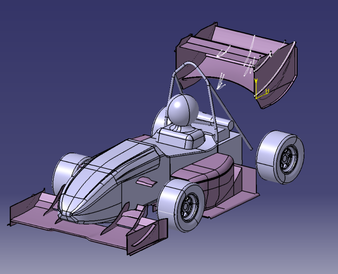
Figure 9. Car model.
6. Numerical results and statistics
The Q-criterion of the racing car is shown in Figure 10. It’s easy to find that the turbulence behind the front wing does not go into the diffuser and the airflow near the outside bypasses the front tires. The downforce of several parts is listed in Table 2. The downforce is greater than that of a single front wing when the rear wing is assembled on the car. A possible reason is that the diffuser acts as a suction channel to accelerate the airflow on the lower surface of front wing. However, this doesn’t mean that it’s good for aerodynamic characteristics because it may have an impact on torques. Unbalanced torques sometimes leads to oversteering. The racer is hard to control the racing car in steering situation. However, this front wing’s statistics is under acceptable range.
Table 2. Downforce and drag of car
downforce | drag | |
Front wing | 362.62N | 45.84N |
Rear wing | 381.36N | 155.26N |
Whole car | 1008.04N | 377.12N |
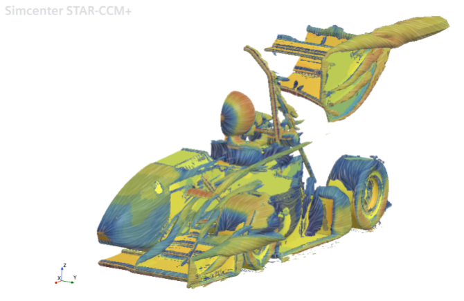
Figure 10. Q-criterion of whole car.
7. Conclusion
The statistics and airfield around the car indicate that the new design is successful. The front wing achieves the design goals and provides enough downforce. It reduces the drag and controls the turbulence as well. However, it is still some way from perfect. One of flaws is that the endplate’s function doesn’t reach the expected result. The airflows tend to come into the central of the front wing from outside. A possible reason is the huge pressure difference between the lower surface of the front wing and atmosphere pressure. Making the endplate into a hook face maybe a functional plan. Another problem is the lifted airflow still have some impact on the rear wing, although the impact is small. A turning vane which has been used in F1 race may help to solve the problem. Besides, endplate foot still has room for improvement. To sum up, the design introduced in this article is fitted to the new car and works well, but it needs more improvement in the next year.
References
[1]. Peng-fei, Gou, et al. "Front wing design of formula SAE racing car based on CFD." 2011 International Conference on Electric Information and Control Engineering. IEEE, 2011.
[2]. Versteeg, H. and Malalasekera, W., “An introduction to computational fluid dynamics,” (Harlow, Longaman, 1995), ISBN 0-582-21884-5.
[3]. Castro, Xabier, and Zeeshan A. Rana. "Aerodynamic and structural design of a 2022 Formula One front wing assembly." Fluids 5.4 (2020): 237.
[4]. Hetawal, Sneh, et al. "Aerodynamic study of formula SAE car." Procedia Engineering 97 (2014): 1198-1207.
[5]. Doddegowda, Punith, Aleksandr L. Bychkovsky, and Albert R. George. Use of computational fluid dynamics for the design of formula SAE race car aerodynamics. No. 2006-01-0807. SAE Technical Paper, 2006.
[6]. Soliman, Paulo Augusto, Mario Eduardo Santos Martins, and Adriano Schommer. Formula SAE Aerodynamics: Design process with focus on drivability. No. 2015-36-0359. SAE Technical Paper, 2015.
[7]. Cravero, Carlo, and Davide Marsano. "Computational investigation of the aerodynamics of a wheel installed on a race car with a multi-element front wing." Fluids 7.6 (2022): 182.
[8]. Jasinski, William J., and Michael S. Selig. "Experimental study of open-wheel race-car front wings." SAE transactions (1998): 2549-2557.
[9]. Basso, Mattia, Carlo Cravero, and Davide Marsano. "Aerodynamic effect of the gurney flap on the front wing of a F1 car and flow interactions with car components." Energies 14.8 (2021): 2059.
[10]. Cole, Evan S. "DESIGN AND VALIDATION OF AN AERODYNAMIC SYSTEM FOR A FORMULA SAE® VEHICLE USING VEHICLE DYNAMIC SIMULATION AND EXPERIMENTATION." (2023).
Cite this article
Chen,X. (2023). Analysis and improvements of a front wing for formula SAE car. Theoretical and Natural Science,13,136-143.
Data availability
The datasets used and/or analyzed during the current study will be available from the authors upon reasonable request.
Disclaimer/Publisher's Note
The statements, opinions and data contained in all publications are solely those of the individual author(s) and contributor(s) and not of EWA Publishing and/or the editor(s). EWA Publishing and/or the editor(s) disclaim responsibility for any injury to people or property resulting from any ideas, methods, instructions or products referred to in the content.
About volume
Volume title: Proceedings of the 3rd International Conference on Computing Innovation and Applied Physics
© 2024 by the author(s). Licensee EWA Publishing, Oxford, UK. This article is an open access article distributed under the terms and
conditions of the Creative Commons Attribution (CC BY) license. Authors who
publish this series agree to the following terms:
1. Authors retain copyright and grant the series right of first publication with the work simultaneously licensed under a Creative Commons
Attribution License that allows others to share the work with an acknowledgment of the work's authorship and initial publication in this
series.
2. Authors are able to enter into separate, additional contractual arrangements for the non-exclusive distribution of the series's published
version of the work (e.g., post it to an institutional repository or publish it in a book), with an acknowledgment of its initial
publication in this series.
3. Authors are permitted and encouraged to post their work online (e.g., in institutional repositories or on their website) prior to and
during the submission process, as it can lead to productive exchanges, as well as earlier and greater citation of published work (See
Open access policy for details).
References
[1]. Peng-fei, Gou, et al. "Front wing design of formula SAE racing car based on CFD." 2011 International Conference on Electric Information and Control Engineering. IEEE, 2011.
[2]. Versteeg, H. and Malalasekera, W., “An introduction to computational fluid dynamics,” (Harlow, Longaman, 1995), ISBN 0-582-21884-5.
[3]. Castro, Xabier, and Zeeshan A. Rana. "Aerodynamic and structural design of a 2022 Formula One front wing assembly." Fluids 5.4 (2020): 237.
[4]. Hetawal, Sneh, et al. "Aerodynamic study of formula SAE car." Procedia Engineering 97 (2014): 1198-1207.
[5]. Doddegowda, Punith, Aleksandr L. Bychkovsky, and Albert R. George. Use of computational fluid dynamics for the design of formula SAE race car aerodynamics. No. 2006-01-0807. SAE Technical Paper, 2006.
[6]. Soliman, Paulo Augusto, Mario Eduardo Santos Martins, and Adriano Schommer. Formula SAE Aerodynamics: Design process with focus on drivability. No. 2015-36-0359. SAE Technical Paper, 2015.
[7]. Cravero, Carlo, and Davide Marsano. "Computational investigation of the aerodynamics of a wheel installed on a race car with a multi-element front wing." Fluids 7.6 (2022): 182.
[8]. Jasinski, William J., and Michael S. Selig. "Experimental study of open-wheel race-car front wings." SAE transactions (1998): 2549-2557.
[9]. Basso, Mattia, Carlo Cravero, and Davide Marsano. "Aerodynamic effect of the gurney flap on the front wing of a F1 car and flow interactions with car components." Energies 14.8 (2021): 2059.
[10]. Cole, Evan S. "DESIGN AND VALIDATION OF AN AERODYNAMIC SYSTEM FOR A FORMULA SAE® VEHICLE USING VEHICLE DYNAMIC SIMULATION AND EXPERIMENTATION." (2023).