


1. Introduction
During the process of takeoff, achieving greater lift force with shorter distance of takeoff run is vital in reducing airport construction costs and ensuring the safety of takeoff [1,2]. In order to generate sufficient lift, the utilization of lift-enhancing devices is essential.
The flap is a movable control device located at the trailing edge of the aircraft wing. By installing flaps on the wing, the wing area can be increased, and the wing curvature can be modified. Increasing the wing area enhances the contact area between the aircraft wing and the airflow, resulting in increased lift under similar pressure conditions. Modifying the wing curvature alters the flow conditions above and below the wing, thereby changing the direction of the aerodynamic forces. This facilitates the takeoff and landing of the aircraft [3,4]. Moreover, by adjusting the position of the flaps during flight, the aircraft’s aerodynamic characteristics can be regulated, resulting in varying levels of drag [5].
The function of flaps is to provide sufficient lift force during takeoff, and regulate the aircraft’s attitude lift during landing through flap adjustments [6,7]. Common types of trailing edge flaps include simple flaps, split flaps, Fowler flaps, and slotted flaps [8,9]. The flaps can be classified into two types based on their installation location and specific functions: leading edge flaps and trailing edge flaps. This article focuses on studying the impact of forces on trailing edge flaps during takeoff. A slotted flap is modeled, with the flap motion being implemented based on the operation of a split flap for the purpose of controlling variables. As finding the appropriate angle of deflection is a crucial factor in improving flight efficiency, this article primarily investigates the influence of flap deflection angles on the aerodynamic forces acting on the aircraft during low-speed flight. The Flow Simulation module is utilized for the analysis of the flow field. The relation between lift and tilt angle of the flap is obtained. From the analysis, for the chosen type of flaps configuration, the optimal flap angle for takeoff is 45°.
This article may offer a reference for the design of flaps.
2. Solidworks flow simualtion
In this article, to Simulate the forces on the aircraft wing, solidworks flow simualtion was used. It is a professional CFD (Computational Fluid Dynamics) software primarily used for simulating fluid flow and heat transfer problems.
This software is embedded in SolidWorks 3D CAD and is well compatible with models created in SolidWorks. It is capable of calculating the effects caused by the fluid movement inside and outside the model. Using SolidWorks Flow Simulation, it is possible to obtain a simple analysis of the interaction between the model presented in this article and the surrounding fluid.
3. Numerical simulation method
The computation of the lift acting upon the aircraft wings is expressed in Equation (1).
\( Y=\frac{1}{2}ρCS{v^{2}}\ \ \ (1) \)
where Y is the force of lift the aircraft, C is the lift coefficient, which is related to the factors such as the angle of attack and the wing shape, v is the speed of the aircraft’s flight, ρ is the density of air, S is the area of the wings. The calculated lift represents the differential forces acting on the upper and lower surfaces of the wing due to the disparity in airflow velocities, resulting in the generation of lift.
The governing equations for simulating fluid flow are as follows:
Mass Conservation Equation:
\( \frac{∂ρ}{∂t}+∇(ρv)=0\ \ \ (2) \)
Momentum Conservation Equation:
\( \frac{∂(ρv)}{∂t}+∇(ρvv)=-∇P+∇τ+ρg\ \ \ (3) \)
Energy Conservation Equation:
\( \frac{∂(ρE)}{∂t}+∇(ρEv)=-∇(Pv)+∇(k∇T)+S\ \ \ (4) \)
In the governing equations, t is time, P is dynamic pressure, which is related to the lift force, τ is the stress tensor, E is the energy per unit volume, k is thermal conductivity coefficient, T is temperature,S is the other energy source.
And in solidworks, There are several equations to determine the physical quantities required for some simulation analysis. These equations are as follows:
\( τ=(μ+{μ_{t}})\frac{dU}{dn}\ \ \ (5) \)
\( {P_{0}}=P{(1+\frac{γ-1}{2}{M^{2}})^{\frac{y}{y-1}}}\ \ \ (6) \)
 is denotes dynamic viscosity and \( {μ_{t}} \) is represents turbulent viscosity. n perpendicular to the aircraft’s wing. \( {P_{0}} \) is kinetic pressure, γ is the specific heat ratio of the gas, M is flow mach number. Based on the given equations and parameters, the lift force experienced by the aircraft during takeoff can be obtained through simulation.
The numerical value of the pressure difference represents the disparity in forces acting on the upper and lower surfaces of the aircraft wing. A larger pressure difference results in a greater lift force, making takeoff easier.
In this article, the choice of trailing edge flaps as the main flap structure is made. In the design process, the volume of the flap section is enlarged to increase the variation in angle of attack and the changes in wing forces. In the final model, the total length is 1.1 m, width is 0.42 m, and height is 0.1 m. The upper surface area of the wing is 0.3 m2, while the upper surface area of the slat is 0.14 m2.
To create the precise shape of the wing, the model is divided into two parts: one for the windward side(left) and the other for the main body of the wing(right), with the parameters mentioned earlier. The linkage mechanism is consisted of three sticks which are used to control the change of flaps’ deflection angle and position. As the shape of linkage mechanism has no connection with the lift force, there are no excessive restrictions imposed on the linkage mechanism. After assembling the components, the final model of the wing and slat is shown in Figure 1.
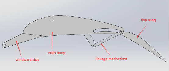
Figure 1. Final model of wing and slat.
In this model, the linkage mechanism is used to control the forward and backward movement. There is a gap between the slat and the main wing body to allow airflow, improving the aerodynamic characteristics of the wing, and facilitating increased lift during takeoff.
4. Three-dimensional simulation
During the simulation, the first step is grid partitioning. In this article, the main issue in the simulation is the force analysis of the slat and wing, and the grid partitioning for the model established in the previous context and the surrounding flow field is shown in Figure 2. The total number of grids is 13526.
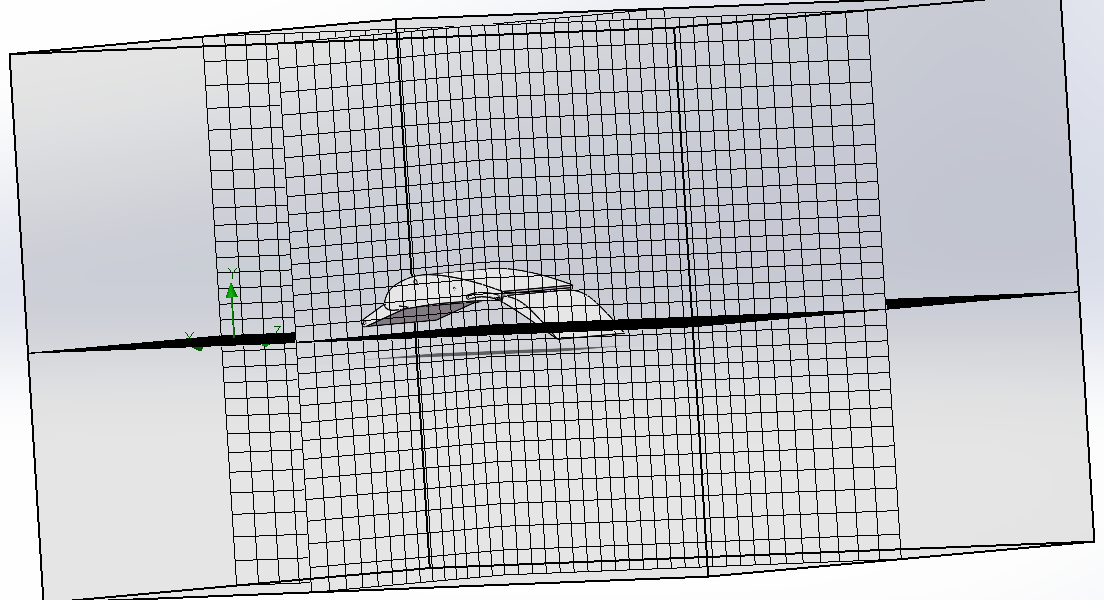
Figure 2. Grid partitioning of model.
The flight during takeoff and landing is taken in air with a density equivalent to standard atmospheric pressure, and the speed during takeoff is lower than the normal flight speed. However, the selection of this speed does not affect the trend of the wing’s force variation. For the purpose of calculation and statistical convenience, a flight speed of 100 m/s is chosen for simulation.
The environment is set at a standard atmospheric pressure with air as the predetermined gas. The flow velocity is 100 m/s. The wing is thermally insulated and completely smooth. In order to eliminate the influence of other variables, the forward and backward movement of the slat will not be considered during the simulation. Only the variation of the angle of attack will be focused on. The result of simulation is shown in Figure 3.
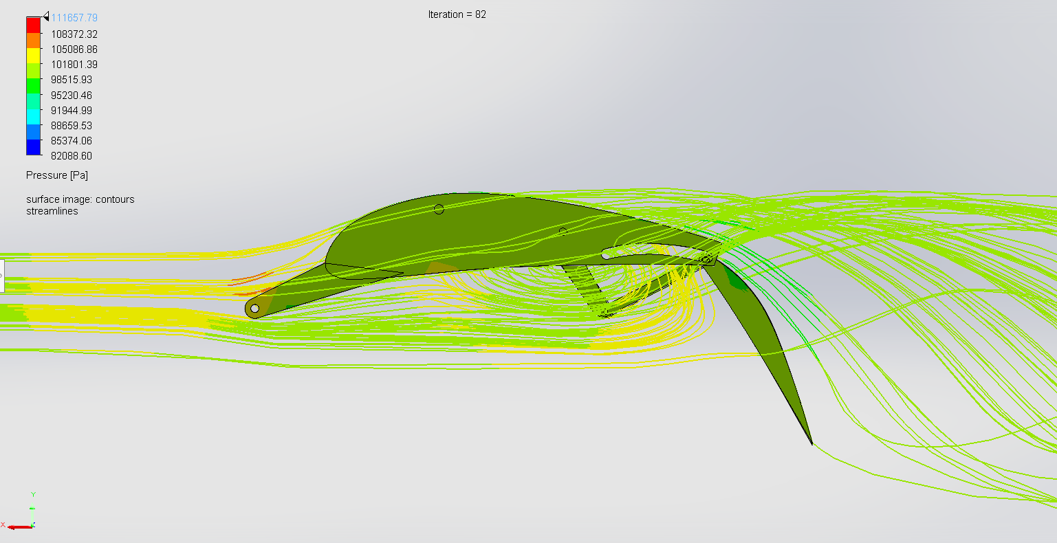
Figure 3. Result of simulation.
In Figure 3, the lines are streamlines and the color of streamlines shows the pressure at the streamlines. The color in the model shows the pressure at the surface of the model. The result can be observed that during the motion, the wing experiences the maximum force on the windward side, indicated by the red-colored streamlines. The upper surface of the wing experiences the least force, indicated by the light blue-colored streamlines. On the lower surface of the wing, due to the presence of vortices, the airflow slows down, resulting in a relatively higher pressure compared to the upper surface. The streamlines in this region are colored yellow, and the rest of the streamlines are also darker compared to those on the upper surface of the wing.
5. Results and discussion
According to the simulation results, during the flight of the aircraft, there will be a circulation of fluid around the lower part of the wing, resulting in higher pressure on the lower surface of the wing compared to the upper surface. This provides additional upward lift for the aircraft, facilitating smooth operations during takeoff and landing. The upper surface of the wing has fewer streamlines, indicating lower pressure compared to the lower surface, and creating a pressure difference that generates lift.
A total of ten simulations are conducted to investigate the effects of various tilt angles. The results are shown in Table 1. The simulation results are fitted with a second-order Gaussian curve, as shown in Figure 4.
Table 1. Pressure Difference vs Tilt Angle.
Case Number | Tilt Angle/° | Pressure Difference/Pa |
1 | 0 | 603 |
2 | 9.9 | 1651 |
3 | 20 | 2203 |
4 | 27.4 | 2306 |
5 | 39.4 | 3311 |
6 | 44.4 | 3030 |
7 | 57.3 | 2908 |
8 | 61.2 | 2949 |
9 | 80 | 2901 |
10 | 87.7 | 3897 |
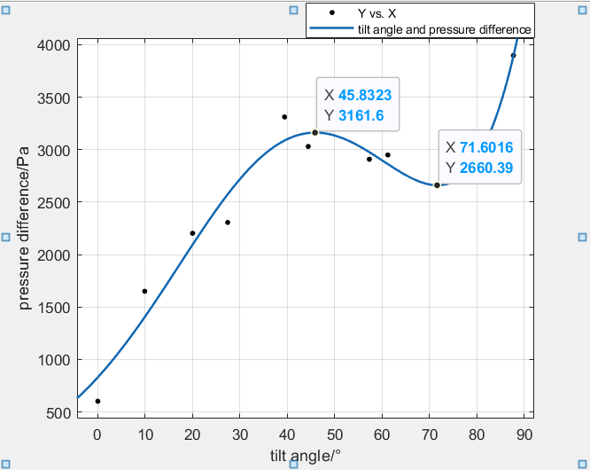
Figure 4. Pressure Difference vs Tilt Angle.
According to the fitting results, in the first half of the fitted curve, as the tilt angle of the flaps increases, the pressure difference gradually increases. It reaches a local maximum value of 3161.6 Pa at approximately 45.8°. As the tilt angle increases over 45°, the pressure on the wing decreases gradually and reaches a local minimum value at 71.6°. Subsequently, as the tilt angle continues to increase, the pressure difference on the wing experiences a sharp increase.
Based on the analysis of the date provided in Figure 4, when the tilt angle reaches 45.8°, the wings acquire the greatest lift force. At this angle, the aerodynamic forces acting on the wings remain relatively stable. Even the flaps are subjected to disturbances and cause changes in the tilt angle, the pressure exerted on the wings remains relatively stable and does not make a great change. The wings get a great lift force with good stability when the tilt angle is 45.8°.
Meanwhile, according to the principles of aerodynamics, the stall is one of the important factors leading to reduced efficiency of the aircraft wing profile. One of the primary conditions for stall is excessive angle of attack [10]. When the flap angle becomes too large, the angle of attack become large, which leads to flow separation. This results in a drastic increase in wing drag and decrease in lift, thereby causing difficulties in takeoff.
As a result, flaps’ deflection angle is related to the lift force. When the tilt angle increases from 0° to 45.8°, the lift force increases smoothly. And when the tilt angle increases from 45.8° to 71.6°, the lift force decreases slowly. When the tilt angle is larger than 71.6°, the lift force has a sharp increase with the tilt angle.
6. Conclusion
As the tilt angle of the flaps increases, the overall aerodynamic shape of the wing changes, resulting in a change in the angle of attack of the wing. Increasing the tilt angle of the flaps can alter the aerodynamic characteristics of the wing, resulting in a greater pressure difference on the wing surfaces. A larger tilt angle causes an increase in the flow velocity of the upper surface, leading to lower pressure, while the flow velocity on the lower surface decreases, resulting in higher pressure.
When the tilt angle is large enough, a significant shear effect occurs between the flaps and the wing, caused by high-speed airflow. This shear effect reduces the velocity difference between the upper and lower surfaces of the wing, thereby diminishing the pressure difference.
When the tilt angle is too large, the overall aerodynamic shape becomes better than smaller tilt angle. At this time, slight disturbances that cause changes in the tilt angle can result in significant alterations in the aerodynamic forces acting on the wing, thereby affecting the longevity of the aircraft’s wings.
Based on the numerical results, for this type of flaps configuration, the optimal flap angle for takeoff is 45°. At this angle, the aircraft achieves the maximum lift, allowing for shorter takeoff distances, and improving the economic efficiency of airport construction and aircraft operations.
References
[1]. Wang K, Hou M. Optimization Method for Unbalanced Takeoff of Domestic Civil Aircraft with Long Runway Length Restriction. Flight Mechanics, 2022, 40(02): 87-94.
[2]. Wang C. Analysis and Assembly Design of Flap Structure for a Certain Type of Aircraft. China Science and Technology Information, 2023(14): 38-41.
[3]. Alam M., Sohn C. H.. Parametric analysis of an oscillating wing energy harvester with a trailing edge flap.
[4]. He C, Huang Y. Optimization of Flap Aerodynamic Load Measurement Method. Civil Aircraft Design and Research, 2023(01): 31-37.
[5]. Zhou J. Simulation and Analysis of Flap Mechanism Motion Reliability. Northeast University, 2022..
[6]. Huang J. Selection and Analysis of Motion Types for Trailing Edge Flaps. Civil Aircraft Design and Research, 2009(03): 8-12+17.
[7]. Li L. Overview of the Technological Development of High-Lift Devices for Large Aircraft. Aeronautical Science and Technology, 2015, 26(05): 1-10.
[8]. Feng W, Yu F, Jiang T, et al. Aerodynamic Characteristics Analysis of Variable Sweep Angle and Variable Airfoil Thickness Wing. Flight Mechanics, 2023, 41(01): 9-13.
[9]. Wei W, Zhang Y, He R, et al. Research on Motion Design of Trailing Edge Flaps for Large Civil Aircraft. Science and Technology Vision, 2018(09): 132-133..
[10]. Guo R. Study on the Application of Trailing Edge Flaps in Large Low Wind Speed Wind Turbines. Lanzhou University of Technology, 2019.
Cite this article
Li,Z. (2023). Influence of flap’s deflection angle on aerodynamic performance of aircraft. Theoretical and Natural Science,14,1-7.
Data availability
The datasets used and/or analyzed during the current study will be available from the authors upon reasonable request.
Disclaimer/Publisher's Note
The statements, opinions and data contained in all publications are solely those of the individual author(s) and contributor(s) and not of EWA Publishing and/or the editor(s). EWA Publishing and/or the editor(s) disclaim responsibility for any injury to people or property resulting from any ideas, methods, instructions or products referred to in the content.
About volume
Volume title: Proceedings of the 3rd International Conference on Computing Innovation and Applied Physics
© 2024 by the author(s). Licensee EWA Publishing, Oxford, UK. This article is an open access article distributed under the terms and
conditions of the Creative Commons Attribution (CC BY) license. Authors who
publish this series agree to the following terms:
1. Authors retain copyright and grant the series right of first publication with the work simultaneously licensed under a Creative Commons
Attribution License that allows others to share the work with an acknowledgment of the work's authorship and initial publication in this
series.
2. Authors are able to enter into separate, additional contractual arrangements for the non-exclusive distribution of the series's published
version of the work (e.g., post it to an institutional repository or publish it in a book), with an acknowledgment of its initial
publication in this series.
3. Authors are permitted and encouraged to post their work online (e.g., in institutional repositories or on their website) prior to and
during the submission process, as it can lead to productive exchanges, as well as earlier and greater citation of published work (See
Open access policy for details).
References
[1]. Wang K, Hou M. Optimization Method for Unbalanced Takeoff of Domestic Civil Aircraft with Long Runway Length Restriction. Flight Mechanics, 2022, 40(02): 87-94.
[2]. Wang C. Analysis and Assembly Design of Flap Structure for a Certain Type of Aircraft. China Science and Technology Information, 2023(14): 38-41.
[3]. Alam M., Sohn C. H.. Parametric analysis of an oscillating wing energy harvester with a trailing edge flap.
[4]. He C, Huang Y. Optimization of Flap Aerodynamic Load Measurement Method. Civil Aircraft Design and Research, 2023(01): 31-37.
[5]. Zhou J. Simulation and Analysis of Flap Mechanism Motion Reliability. Northeast University, 2022..
[6]. Huang J. Selection and Analysis of Motion Types for Trailing Edge Flaps. Civil Aircraft Design and Research, 2009(03): 8-12+17.
[7]. Li L. Overview of the Technological Development of High-Lift Devices for Large Aircraft. Aeronautical Science and Technology, 2015, 26(05): 1-10.
[8]. Feng W, Yu F, Jiang T, et al. Aerodynamic Characteristics Analysis of Variable Sweep Angle and Variable Airfoil Thickness Wing. Flight Mechanics, 2023, 41(01): 9-13.
[9]. Wei W, Zhang Y, He R, et al. Research on Motion Design of Trailing Edge Flaps for Large Civil Aircraft. Science and Technology Vision, 2018(09): 132-133..
[10]. Guo R. Study on the Application of Trailing Edge Flaps in Large Low Wind Speed Wind Turbines. Lanzhou University of Technology, 2019.