


1. Introduction
Variable Cycle Engine (VCE) is an engine that can adjust the thermal cycle by changing the duct to allow different ratios of air to flow through the variable engine, by adjusting the bypass ratio of this engine, the VCE can function like different types of conventional engines, by imitating their thermal cycles and adjusting the bypass ratio to fit the most desired engine type suitable for the current Mach number. therefore, the VCE would have exceptional performance at a wide range of speeds. A growing number of companies are investing in this topic. Currently, the VCE is a relatively new technology. The research regarding this subject is limited, but this engine is quickly gaining attention, and there have been advancements in the structure of the VCE. This paper explores the differences between these structures and their pros and cons. This research used document analysis and case study. It has included various other research regarding different types of VCE, and real VCEs that are at test or in service. This research is meaningful to those who want to know an overview of the VCE, and it would be good for those who want to get a brief insight into current VCE designs.
2. A brief introduction to the variable cycle engine
Variable Cycle engine or VCE is an engine that can adjust the thermal cycle by changing the duct to allow different ratios of air to flow through the variable engine, by adjusting the bypass ratio of this engine, the VCE can function like different types of conventional engines, by imitating their thermal cycles and adjusting the bypass ratio to fit the most desired engine type suitable for the current Mach number. therefore, the VCE would have exceptional performance at a wide range of speeds.
The VCE at subsonic speeds would allow a high bypass ratio turbo fan to have a much lower specific fuel consumption, while during supersonic flight the VCE may want a higher thrust and would require a lower bypass ratio, or even function as a complete turbojet engine which has no bypass. It is not hard to see the VCE is mostly favorable to supersonic shuttles in the civilian market and military aircrafts requiring supercruise abilities, especially for stealth fighters.
The concept of the VCE was first proposed in the 1960s by General electrics. And the first VCE on active service was the J58 engine powering the SR 71 Blackbird. The engine, differs from modern VCEs, can adjust between a turbojet and a ramjet. After the 1980s, however, because of various global crises, companies are no longer keen on the research of supersonic passenger shuttles. Hence the research about VCEs shifted from civilian to complete military.
In the 1990s, General electrics developed the YF120 VCE for the advanced tactical fighter program, installing the engine on the two fighters YF23 and YF22, competing against the YF119, a conventional turbojet engine, resulted in better performance -on both platforms, YF23 and YF22, of the program-in specific fuel consumption, military thrust, supercruise, and afterburner thrust [1]. Subsequently, in 2007, the US Air Force began to develop the demonstrator engine for the next generation fighter. This program later yielded two products the GE XA100 and the PW XA101. Both are VCE [2-3].
3. The mechanisms of the variable cycle engine
Currently, there are two types of mainstream architecture that have emerged from VCE research.
VCE Architecture One: Dual Bypass Hybridization, the first VCE to be installed on a fighter jet. This architecture, because of its fairly simple design, is at present the most widely used in the VCE research. Its architecture is presented in Fig.1. The F120 VCE, which is designed for advanced tactical fighters F-22 and F-23, is an engine of this structure [4].
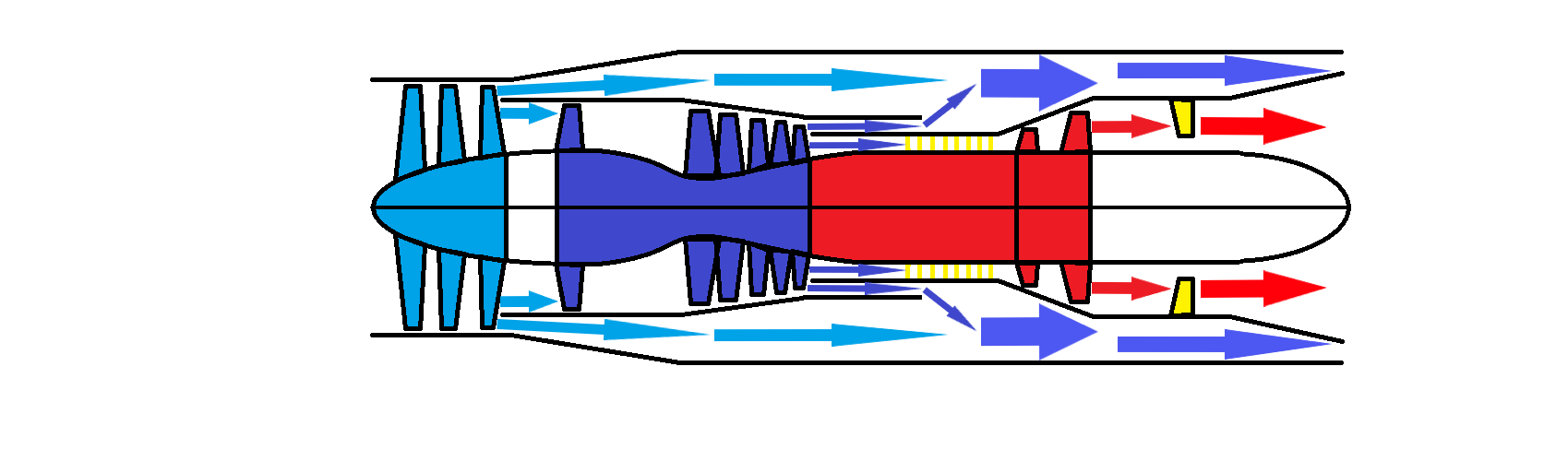
Figure 1. Dual Bypass Hybridization.
This engine's third-stage fan or core-driven fan stage (CDFS) is coupled to the high-pressure compressor (HPC) and driven by the high-pressure turbine (HPT) [4]. The pressure ratio of the CDFS can be modified to adjust the flow rate of the core engine and vary the bypass ratio. A mode selection valve (MSV) is provided to vary the operational mode of the engine. The adjustable low-pressure turbine (LPT) guide alters pressure ratio of the LPT and controls the distribution of HPT and LPT power. The use of Variable Area Bypass Injectors (VABI), specifically the Front Variable Area Bypass Injector (FVABI) and the Rear Variable Area Bypass Injector (RVABI), plays a crucial role in regulating the mass flow of the outer bypass and the operating line of the fan.
VCE Architecture Two: Fig. 2 below depicts the fundamental configuration of the second VCE architecture studied, separate mixing of dual bypass. The framework underpinning this configuration is fundamentally diverse from the first VCE architecture, as the outer bypass and the CDFS bypass are now merged separately in the mixer unit. This configuration does not involve an RVABI or FVABI unit, but rather two RVABIs are utilized [4].
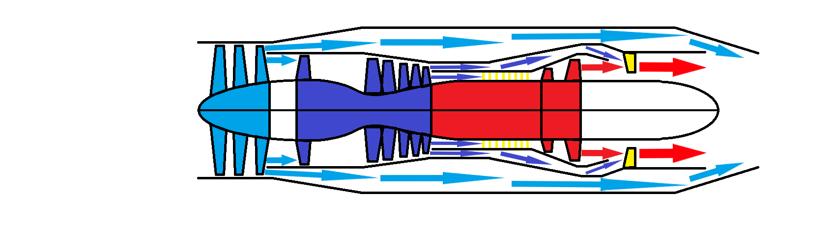
Figure 2. Separate Mixing of Dual Bypass.
It can be simply observed that Architecture One has a simple configuration but with a relatively small specific fuel consumption decrease rate of approximately 4% during subsonic cruising at a speed of Mach 0.9 and altitude of 13.5 kilometers. When compared to Architecture One, Architecture Two has an improved decrease rate of specific fuel consumption, reaching approximately 9% [4]. Both designs optimize the infrared stealth performance, with Architecture 1 being more capable of reducing heat signatures, due to the larger bypass thickness of cold air surrounding the high temperature CDFS airflow.
3.1. Bypassing and non-bypassing mode of the engine
This research will mostly feature the architecture of the second VCE. When in bypassing mode, both mode selection valves are open, enabling the two bypasses to airflow, this engine will work at a two-bypass stage, creating a large bypass ratio, and improving propulsion efficiency. When the engine enters non-bypassing mode, the MSV is closed, resulting in the airflow completely passing through the inner CDFS duct, which would create a significantly larger thrust, but efficiency would decrease. So, the VCE would alter between these two stages by distributing different ratios of airflow through the three ducts. Below are three significant speed intervals and the corresponding bypass ratio of the VCE(see Table 1-3).
Table 1. Extreme high bypass ratio at subsonic.
Design Parameters | Value |
Ma | 0 |
Fan Bypass Ratio | 0.46 |
CDFS Bypass Ratio | 0.164 |
Table 2. Medium bypass ratio at transonic.
Design Parameters | Value |
Ma | 1 |
Fan Bypass Ratio | 0.1 |
CDFS Bypass Ratio | 0.08 |
Table 3. No bypass at speed much greater than Ma.1[5].
Design Parameters | Value |
Ma | 1.45 |
Fan Bypass Ratio | 0 |
CDFS Bypass Ratio | 0 |
3.2. Afterburner mode
The afterburner mode differs greatly from the prior modes. Unlike them which ignition appears in the combustion chamber, the afterburner mode has dual ignition, the first would happen in the ignition chamber then the second in the afterburner. And, to differ from conventional turbojet engines with afterburners, the VCE would not reignite the combusted air coming from the ignition chamber, instead would be mixing oxygen-rich air in the RVABI of the CDFS bypass the combusted air. This would give rise to a significant amount of increase in thrust compared to that of a conventional afterburner(see Figure 3).
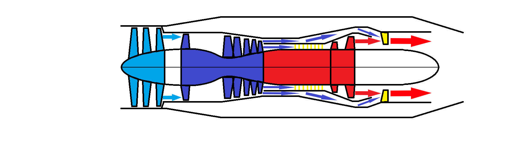
Figure 3. Afterburner mode (architecture two)
It can easily be interpreted that the outer bypass experiences no airflow at all. The MSV would direct all flow to the inner bypass and the CDFS duct. The inner bypass would mix with the CDFS air just before the afterburner. Then the afterburner ignites this flow, generating high thrust. In this mode the core engine can be seen as a turboshaft, powering the turbojet bypass without the turbine. Therefore the exiting velocity of airflow U would become greater than the conventional turbojet, allowing not only higher thrust but also generating more force at high Mach numbers.
4. The advantage of the variable cycle engine
For aircraft destined to execute a diverse range of missions, encompassing subsonic, transonic, and supersonic flight velocities while maintaining low fuel consumption, it is highly desirable to have an engine that combines the attributes of both a high-bypass engine for subsonic flight velocities and a low-bypass or even no bypass engine for supersonic flight velocities. Below this research will discuss the improvements achieved by the VCE at the subsonic and supersonic reign.
4.1. Advances in the subsonic environment
Assuming that the speed of flow in front of the fan is V, the power input to the fan is P, and the air flux through the fan is q (kg / s), the fan does work on the air so that the air flow rate increases to V+ΔV.
In order to avoid unnecessary details to complicate the problem, if the process of the fan works on the air and the flow of no loss (that is, 100% efficiency), then according to the conservation of energy, the fan per second on the air work is equal to the kinetic energy increment of the air flowing through the fan at the same time:
\( P=(\frac{1}{2})*q*ΔV*(2V+ΔV)\ \ \ (1) \)
According to the momentum theorem, it is easy to determine that q*ΔV is the thrust of the fan. Thrust F would equal to F=2P/(2V+ΔV).
The input power and the velocity of the incoming air will both remain constant. Obviously, the smaller the velocity increment, the greater the thrust, when ΔV→0 the thrust will tend to be maximum, P/V.
Therefore, when ΔV→0, air flux q→∞.
We can conclude that if we want to increase thrust but keep SFC low, P must stay the same. Hence, the bypass ratio would increase(see Figure 4).
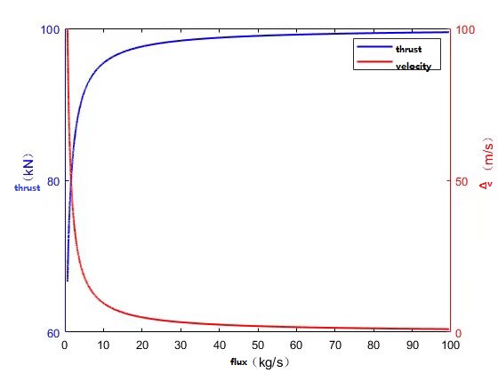
Figure 4. The relation of thrust and flux comparing to velocity and flux.
But as V increases the thrust would decrease, therefore the VCE would distribute more air to the CDFS duct to allow more air to exit at greater speeds. By doing so the engine allows for better SFC at all subsonic speeds, surpassing the turbojet at fuel consumption, at subsonic.
4.2. Advances in the supersonic environment
Although the VCE features like the conventional turbojet at supersonic, this engine will offer benefits unavailable on the conventional jet engine. The VCE would allow for the MSV to distribute a thin portion of air to the outer bypass mixing with the exiting air behind the engine; this would decrease the infrared signature of the plane. Although not increasing thrust, the ability within the military field would be exceptionally beneficial to stealth fighter’s super cruise ability, and within the civilian area it would decrease noise generated from the engine, allowing for more comfort during supersonic flight.
5. Conclusion
This paper is targeted to explore the basic mechanism of various VCEs and to see how this new engine brings people better performance over conventional jets. In this research, the following conclusions are obtained: 1)The VCE would drastically increase improvement for aircraft flying subsonic and supersonic speeds. 2)The VCE has two main architectures, the Dual Bypass Hybridization which mixes airflow of the LPT and HPT, then mixing them with the CDFS duct. The Separate Mixing of Dual Bypass, which mixes the CDFS bypass and the CDFS duct then with the outer bypass at the exit of the engine. This type of engine can create higher thrusts when afterburning. The VCE would be significantly more efficient compared to turbojets at subsonic, by airflow through the bypass. This research has not explored the VCE engine in areas such as the ramjet VCE and the scramjet VEC. Future research would focus more on hypersonic VCEs, ramjet scramjet, as well as the turbofan jet VCE of the topic of this research.
References
[1]. Bei Liu. Overall Performances of Interstage Turbine Mixed Architecture Variable Cycle Engine, Journal of Propulsion Technology, ISSN 1001-4055, CN 11-1813/v,2022:2
[2]. GE Aerospace XA100 Adaptive Cycle Engine, 2023, https://www.geaerospace.com/ propulsion/military/xa100
[3]. Pratt and Whitney. Pratt and Whitney Military Engines, 2023, https://www.prattwhitney.com/
[4]. RunFu Liu. Numerical of mixing characteristic of rear variable area bypass injector with lobed structure. Journal of Aerospace Power, ISSN 1000-8055, CN 11-2297/V , 2022:4
[5]. Wang Hao. Mode Transition Modeling and Control Law Design Method of Variable Cycle Engine, Journal of Propulsion Technology, 1001-4055(2022) 01-210058-10, 2022:5
Cite this article
Li,Y. (2023). Mechanisms and advantages of the variable cycle engine. Theoretical and Natural Science,14,52-57.
Data availability
The datasets used and/or analyzed during the current study will be available from the authors upon reasonable request.
Disclaimer/Publisher's Note
The statements, opinions and data contained in all publications are solely those of the individual author(s) and contributor(s) and not of EWA Publishing and/or the editor(s). EWA Publishing and/or the editor(s) disclaim responsibility for any injury to people or property resulting from any ideas, methods, instructions or products referred to in the content.
About volume
Volume title: Proceedings of the 3rd International Conference on Computing Innovation and Applied Physics
© 2024 by the author(s). Licensee EWA Publishing, Oxford, UK. This article is an open access article distributed under the terms and
conditions of the Creative Commons Attribution (CC BY) license. Authors who
publish this series agree to the following terms:
1. Authors retain copyright and grant the series right of first publication with the work simultaneously licensed under a Creative Commons
Attribution License that allows others to share the work with an acknowledgment of the work's authorship and initial publication in this
series.
2. Authors are able to enter into separate, additional contractual arrangements for the non-exclusive distribution of the series's published
version of the work (e.g., post it to an institutional repository or publish it in a book), with an acknowledgment of its initial
publication in this series.
3. Authors are permitted and encouraged to post their work online (e.g., in institutional repositories or on their website) prior to and
during the submission process, as it can lead to productive exchanges, as well as earlier and greater citation of published work (See
Open access policy for details).
References
[1]. Bei Liu. Overall Performances of Interstage Turbine Mixed Architecture Variable Cycle Engine, Journal of Propulsion Technology, ISSN 1001-4055, CN 11-1813/v,2022:2
[2]. GE Aerospace XA100 Adaptive Cycle Engine, 2023, https://www.geaerospace.com/ propulsion/military/xa100
[3]. Pratt and Whitney. Pratt and Whitney Military Engines, 2023, https://www.prattwhitney.com/
[4]. RunFu Liu. Numerical of mixing characteristic of rear variable area bypass injector with lobed structure. Journal of Aerospace Power, ISSN 1000-8055, CN 11-2297/V , 2022:4
[5]. Wang Hao. Mode Transition Modeling and Control Law Design Method of Variable Cycle Engine, Journal of Propulsion Technology, 1001-4055(2022) 01-210058-10, 2022:5