


1. Introduction
Wireless energy transmission is a non-contact way of transferring energy between the power source and the device, i.e. through electromagnetic induction, resonance, radio frequency, microwaves and lasers, etc. Since there is no cable connection between the power source and the load, wireless energy transmission technology is safer, more convenient and more reliable than traditional contact energy transmission technology.
"Beamforming" is one of the hot topics of research in the field of wireless charging technology. The Mag-MIMO (Magnetic-MIMO) wireless charging system developed by the Massachusetts Institute of Technology (MIT) in the USA is the first to apply beamforming technology to wireless charging. Based on this technology, the wireless charging system allows energy that would otherwise be transmitted omnidirectionally to be transmitted in one or more specific directions. This will help to extend the charging distance, improve charging efficiency and enhance interference immunity.
The Industrial Internet of Things is the continuous integration of various types of acquisition and control sensors or controllers with sensing and monitoring capabilities, as well as mobile communication and intelligent analysis technologies into all aspects of the industrial production process, thereby significantly increasing manufacturing efficiency, improving product quality, reducing product costs and resource consumption, and ultimately realising a new stage of upgrading traditional industry to intelligence. The inevitable cost of wiring in the construction of the Industrial Internet of Things (IoT) not only hinders the development of IoT and Industry 4.0, but also sets obstacles to the development of smart grids and smart cities. Large-scale sensor installations require wiring complex infrastructures that are costly and take a long time to install [1]. Wireless power transmission technology is a good solution to this problem, not only saving the problem of cable laying and battery replacement, but also eliminating the safety risks associated with cumbersome wiring.
HFSS is a numerical solution of Maxwell's set of equations at full wave, using scientific computing techniques to solve the electromagnetic properties of three-dimensional structures [2]. With the development of computing technology, simulation based on scientific computing has developed into the third pillar of science alongside theoretical analysis and scientific experimentation, and has in fact become a major tool in engineering design. Thanks to the powerful computing power of computers and the continuous development of numerical algorithms for electromagnetic fields, ANSYS HFSS has been able to solve various engineering problems accurately and efficiently, directly obtaining the electromagnetic properties of arbitrary three-dimensional structures, including radiation direction diagrams, S-parameters and field distributions, helping engineers to gain intuitive insight into the core of their designs, free from complex theoretical derivations and time-consuming prototyping [3]. Many of today's antenna and microwave engineers have made HFSS an essential tool in their work and part of the design process, using simulations to determine design solutions and carry out parameter optimisation and fine tuning, followed by processing. Many difficult and highly specified antennas and microwave devices have been designed successfully with the help of HFSS.
For wireless power transmission technology, whether it is near-field transmission or far-field transmission, stability and efficiency are factors to be considered. Beamforming technology is one of the technologies that can improve the anti-interference capability, directivity and efficiency of the system without changing the transmitting power [4]. It is the construction of the shape of the beam by adjusting the signal on each antenna array element for weighted summation, so that the antenna beam is directed in a specific direction, i.e. the antenna energy is focused on a specific user. Beamforming is not only far more. Not only is beamforming far more efficient than omni-directional transmission, this technique also reduces interference with other signals [5].
Overall, inductively coupled wireless charging technology is very mature. Far-field electromagnetic coupling generates a high frequency electromagnetic wave on the transmitter side and uses an antenna to transmit the energy into space as an electromagnetic wave. At the receiving end, the antenna is also used to receive the electromagnetic waves generated at the charger end to receive the energy, and later a rectifier is used to convert the electromagnetic energy into direct current to charge the battery. In this paper we will use ANSYS HFSS software to create an antenna array and analyse the role of beamforming techniques for wireless power transmission systems.
Array antennas are a class of antennas consisting of no less than two antenna units arranged in a regular or random pattern, which can be properly excited to obtain predetermined radiation characteristics. Beamforming is a key technology for array antennas, which improves the signal-to-noise ratio by forming a certain shape of the beam to point in the desired direction. The design process of an array antenna includes antenna unit design, antenna array simulation, antenna layout and integrated integration. In this design, the finite array domain decomposition method (FADDM) is used to simulate the antenna array.
FADDM can analyse the whole array compared to the cell method, supports different magnitude of cell excitation and only needs to do adaptive mesh dissection on one cell and then replicate it periodically to the whole array. The use of the domain decomposition method also reduces computer resource requirements, reducing computation time by calling memory on a distributed cluster. The study of power wireless transmission has gone beyond the scope studied by circuit theory, and field theory must be used to more realistically describe the electromagnetic field relationships between antennas. HFSS, included in ANSYS Electronics Desktop, is a full-wave three-dimensional electromagnetic simulation software based on the finite element method of electromagnetic field to analyse microwave engineering problems, with its powerful, friendly interface and accurate calculation results. It makes the simulation more realistic and effective, and has a certain reference value for the construction of industrial IoT wireless power transmission systems [6].
2. Main body
There are two ways to simulate excitation for arrays, one is network analysis and the other is composite excitation [7]. network analysis works by setting the excitation for multiple ports in sequence, while setting the excitation for the other ports to zero and doing multiple simulations until all ports are simulated. Composite excitation is a single solution for a set of excitation sources with defined phase and amplitude, and iteratively solves the multi-port problem to obtain a solution for a set of excitations much faster.
The domain decomposition method (DDM) is a distributed memory computation by distributing the mesh onto a number of nodes, which breaks the memory limitation, but the DDM is still performed on a single mesh as the mesh dissection problem is not solved. For the finite array domain decomposition method, HFSS uses a reusable DDM cell solution array, which can be extended into a finite array by a simple setup, and can directly import the cell mesh obtained by the cell method and copy the mesh to the rest of the array, then use DDM to solve the entire array mesh, which is FADDM [8]. This method greatly reduces the time required to dissect the mesh for finite array analysis and solves the problem of complex meshes. With the same hardware, FADDM can carry larger arrays, and because FADDM takes into account the edge effects of the array and the coupling between cells, it is as accurate as direct full-model modelling in figure 1 and can be converted quickly from cells to finite large arrays [9].
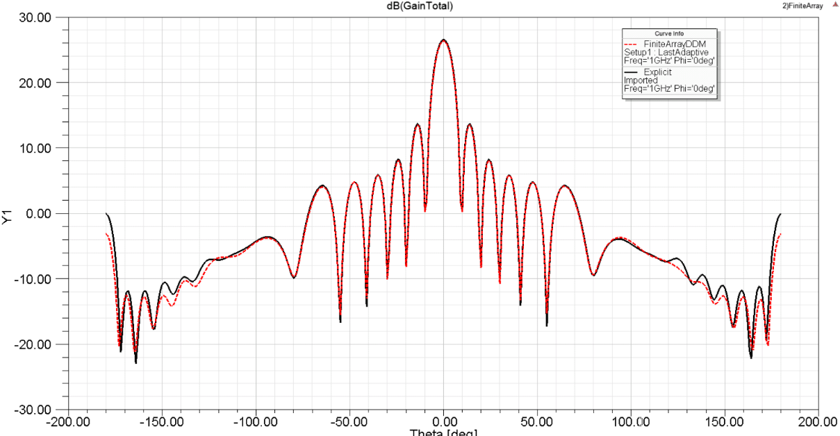
Figure 1. Accuracy Comparison between FADDM & Explicit Import (credit: original).
In this paper, a simulation model of a finite large array of waveguides is developed in the manner above. Firstly, the waveguide array cell is constructed with a radome above the cell with a thickness of 0.583, a dielectric constant of 4.1 and a ground plane on the lower surface. Below are two sections of waveguide filled with different characteristics, both with a radius of 7.222mm and the remaining characteristics are height =6.388mm, \( {ɛ_{r}} \) =1.9 and height =16.304mm, \( {ɛ_{r}} \) =2.1 respectively. The array was laid out as an equilateral triangle with adjacent cells spaced 16.5mm apart. An air domain with a height of 65mm was then created based on the shape of the radome, and master-slave boundaries (primary and secondary in the 2020 version) were set for each opposing face of the air domain in turn to simulate the periodicity of the array. Then right click on the upper surface of the air domain and select Assign Excitation to add the Floquet port, set Number of Modes to 2, Frequency to 10.8GHz, set Phi to (0, 0, 90) deg and Theta to (0, 60, 5) deg in Scan Angles, and finally Simulation is performed in figure 2.
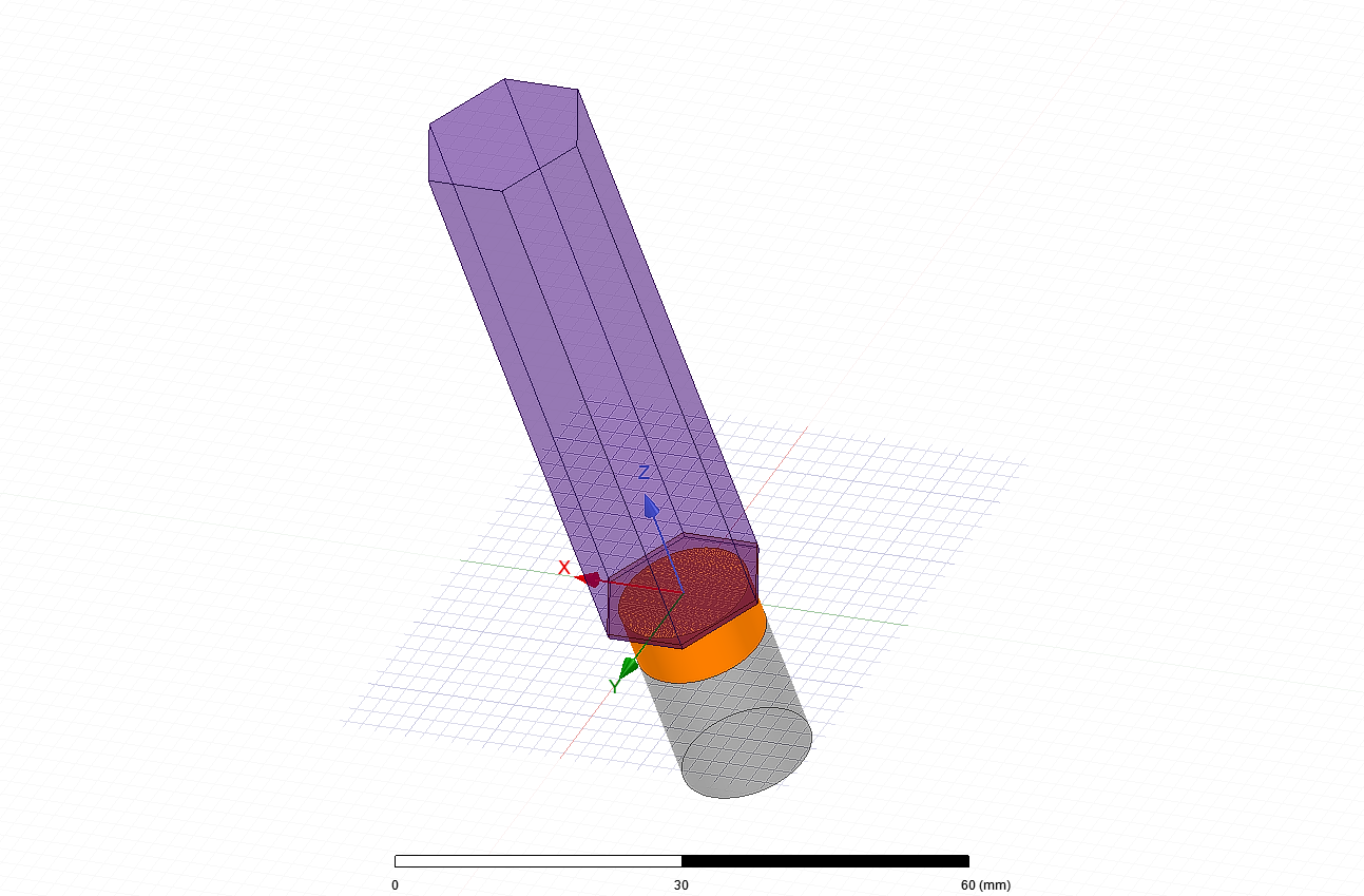
Figure 2. Unitary Method Simulation Model (credit: original).
After completing the above simulation, delete Floquet Port and right click on the top of the cell and select face/radiation to create the radiation boundary. Next, set the Maximum Number of Passes to 1 in Driven Solution Setup and uncheck Do Lambda Refinement to ensure no additional meshing occurs. In the Project Manager right-click on the Model and select Create Array, where the array periodic orientation and the number of cells are defined. Considering the boundary effects of the array, it is necessary to set the (1, 1) and (3, 3) cells to Padding in the Active Cell, where the 9 cell array will become 7 cells. Select (2, 2) cells in the Post Processing Cell to divide and display the grid in the output. Right click on Excitation and select Edit Souse to define the excitation, set the Magnitude to 1 for each port and the phase difference between Mode 1 and Mode 2 to 90°, then run the simulation as shown in figure 3.
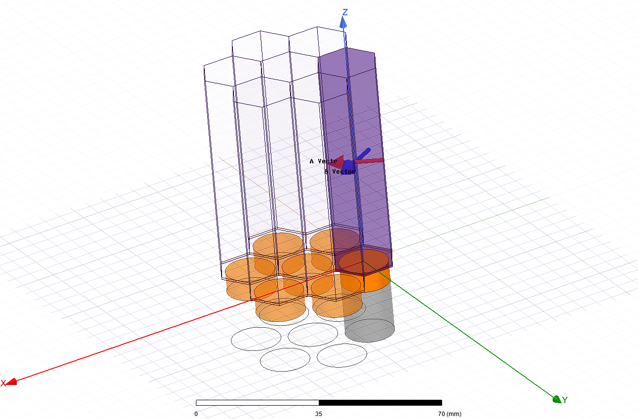
Figure 3. FADDM Simulation Model (credit: original).
After running the simulation, the following results can be obtained. The active S-parameters and radiation pattern for cell (2, 2) are shown below in figure 4 and figure 5. In HFSS, Active S-parameters are given as a liner combination of the regular S-parameters, with some weights ‘a’, based on the matrix equation b=S*a. If \( {a_{m}} \) ≠0, define \( {Acrive\_S_{m}} \) , m=1…N. Definition as followed :
\( {Acrive\_S_{m}}=\sum _{n=1}^{N}{S_{mn}}\frac{{a_{n}}}{{a_{m}}} \) (1)
\( Acrive\_S=Sa \) (2)
From the results of the cell method simulation, it can be seen that the active S-parameters of a single antenna cell gradually decrease from -7.87 dB at 9.20 GHz to -18.19 dB at 10.8 GHz and show an overall linear trend. The directional diagram shows that the radiation of the single antenna is circular and has no obvious directionality.
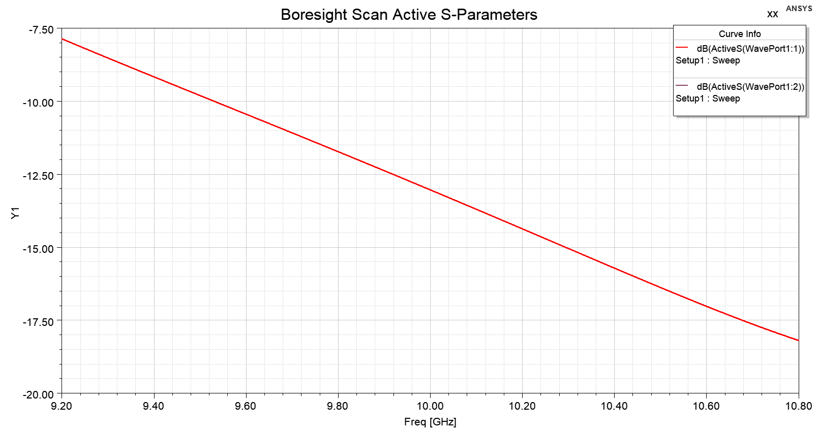
Figure 4. Active S-Parameters of the Antenna Unit (credit: original).
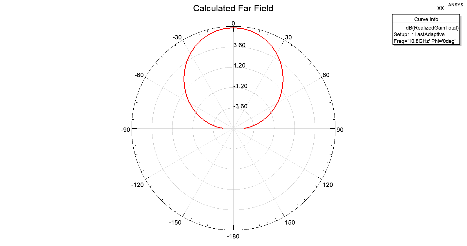
Figure 5. Radiation Pattern of the Antenna Unit (credit: original).
As can be seen from the FADDM simulation results, the active S-parameters in figure 6 of Wave Port1 in excitation mode 1 and excitation mode 2 gradually decrease from -4.02dB and -3.98dB at 9.20GHz and reach -8.99dB and -8.98dB at 10.8GHz, with an overall curve showing a downward depression, and this trend is stronger in excitation mode 1 than in excitation mode 2. The arrays in this simulation show good directionality in figure 7, with the strongest fields at zero degree phase and correspondingly weaker fields at other phases.
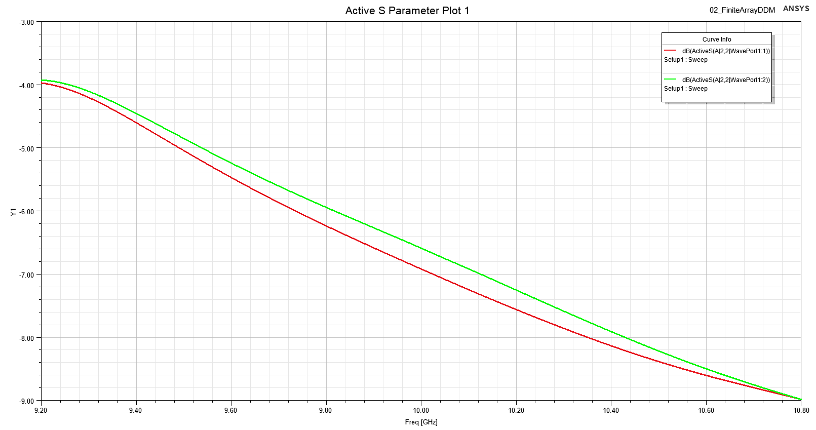
Figure 6. Active S-Parameters of the Antenna Array (credit: original).
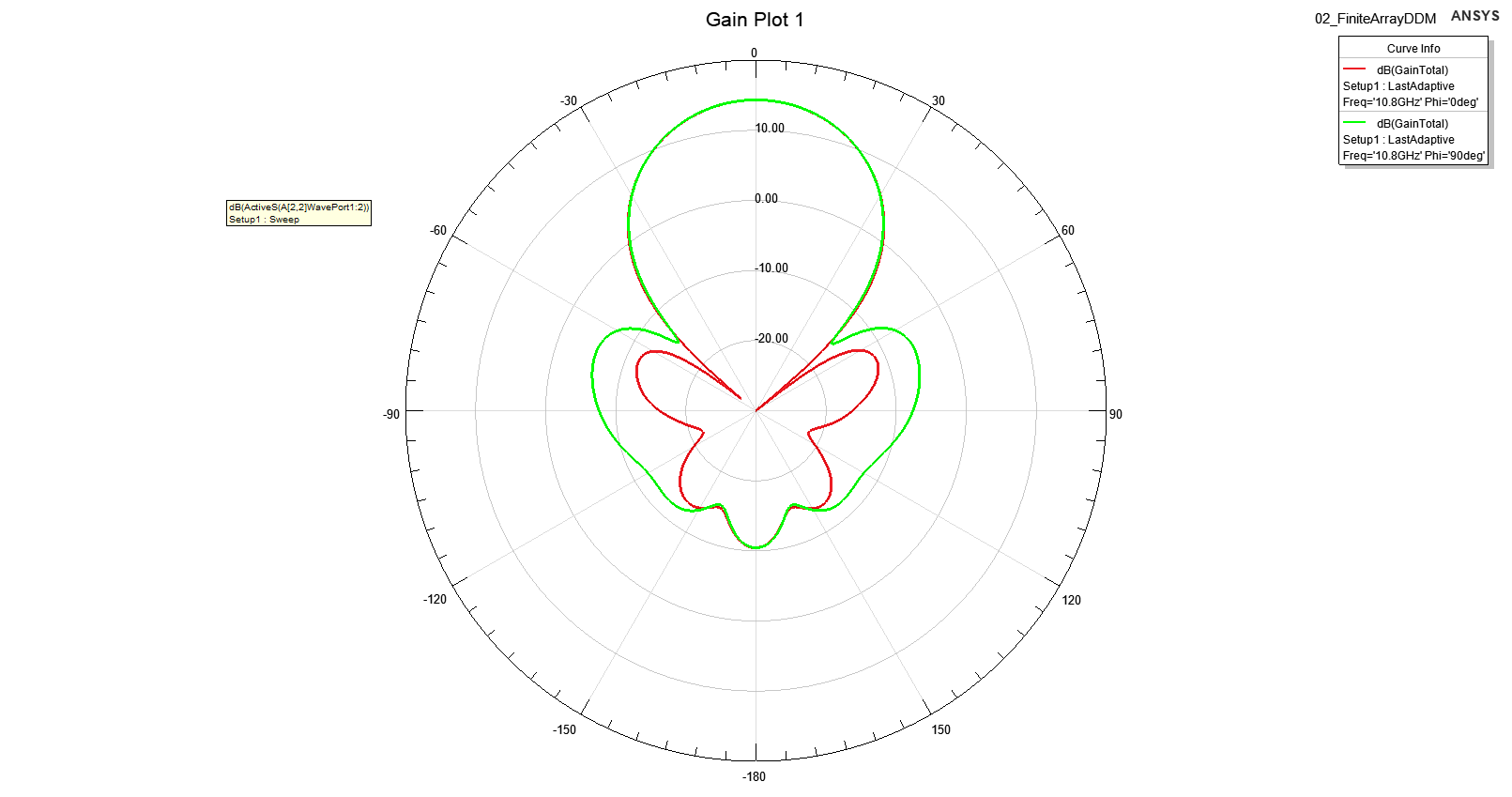
Figure 7. Radiation Pattern of the Antenna Array (credit: original).
The comparison shows that the overall S-parameters of the antenna array are higher than those of the individual antenna units and that the antenna array shows better directivity as well as resistance to fading in the directional diagram. The application of array antennas and beamforming technology can improve transmission efficiency and reduce energy losses in the construction of wireless power transmission systems. Beamforming in conjunction with wireless power transmission technology can reduce the cost of cabling while increasing the efficiency of energy utilization [10].
3. Conclusion
This paper presents a comparative analysis of the performance of antenna units and antenna arrays based on HFSS simulations, showing that the application of beamforming technology has multiple improvements on antenna performance. The antenna array with beamforming technology shows good fading resistance and directionality, which can be better applied in the construction of industrial Internet.
In this paper, the design idea and simulation details of the antenna are demonstrated in detail, based on which the simulation of the antenna unit and the array are completed by HFSS, and the built-in functions are used to generate active S-parameter curves and directional maps to verify the effect of beamforming on the antenna. The active antenna array simulation model presented in this paper has good directivity and better fading resistance compared to a single antenna.
By comparing the simulation results of the two antennas and the design of the model details, this paper demonstrates the role played by beamforming technology in the construction of the Industrial Internet, which might be the guide for the design and characterisation of transmitting antennas in wireless power transmission systems.
References
[1]. Li Shining, Luo Guojia. Overview of industrial IoT technologies and applications[J]. Telecommunications Network Technology, 2014.
[2]. Simulator H F S. HFSS[J]. 2005.
[3]. Miao, Huai, Fu, Wenzhen, Liu, Chunyuan. Application of ANSYS in wireless power transmission systems[J]. Computer Knowledge and Technology, 2020.
[4]. Zeng ZQ, Chen W. Influence of transmission distance on resonant wireless energy transmission system[J]. Electrical Switching, 2016.
[5]. Huang M Y. Ultra-compact concurrent multi-directional beamforming receiving network for high-efficiency wireless power transfer (WPT)[D]. Georgia Institute of Technology, 2018.
[6]. Yu LNA, Hao P, Liu WIT. Performance evaluation of wireless charging process based on beamforming [J]. Electronic Design Engineering, 2019.
[7]. Huang M Y. Ultra-compact concurrent multi-directional beamforming receiving network for high-efficiency wireless power transfer (WPT)[D]. Georgia Institute of Technology, 2018.
[8]. Solaris S. 1. Getting Started with HFSS[J].
[9]. Guo H. Technical analysis of wireless energy transmission in power systems [J]. Industrial Design, 2015.
[10]. Shi Hao Bo, Guo Shi Yang. Analysis of cost control in distribution line construction enterprises[J]. Economic and technological collaboration information, 2015.
Cite this article
Ma,Y. (2023). The application of beam-forming technology of wireless power transfer in IIoT (industrial internet of things). Theoretical and Natural Science,19,44-51.
Data availability
The datasets used and/or analyzed during the current study will be available from the authors upon reasonable request.
Disclaimer/Publisher's Note
The statements, opinions and data contained in all publications are solely those of the individual author(s) and contributor(s) and not of EWA Publishing and/or the editor(s). EWA Publishing and/or the editor(s) disclaim responsibility for any injury to people or property resulting from any ideas, methods, instructions or products referred to in the content.
About volume
Volume title: Proceedings of the 2nd International Conference on Computing Innovation and Applied Physics
© 2024 by the author(s). Licensee EWA Publishing, Oxford, UK. This article is an open access article distributed under the terms and
conditions of the Creative Commons Attribution (CC BY) license. Authors who
publish this series agree to the following terms:
1. Authors retain copyright and grant the series right of first publication with the work simultaneously licensed under a Creative Commons
Attribution License that allows others to share the work with an acknowledgment of the work's authorship and initial publication in this
series.
2. Authors are able to enter into separate, additional contractual arrangements for the non-exclusive distribution of the series's published
version of the work (e.g., post it to an institutional repository or publish it in a book), with an acknowledgment of its initial
publication in this series.
3. Authors are permitted and encouraged to post their work online (e.g., in institutional repositories or on their website) prior to and
during the submission process, as it can lead to productive exchanges, as well as earlier and greater citation of published work (See
Open access policy for details).
References
[1]. Li Shining, Luo Guojia. Overview of industrial IoT technologies and applications[J]. Telecommunications Network Technology, 2014.
[2]. Simulator H F S. HFSS[J]. 2005.
[3]. Miao, Huai, Fu, Wenzhen, Liu, Chunyuan. Application of ANSYS in wireless power transmission systems[J]. Computer Knowledge and Technology, 2020.
[4]. Zeng ZQ, Chen W. Influence of transmission distance on resonant wireless energy transmission system[J]. Electrical Switching, 2016.
[5]. Huang M Y. Ultra-compact concurrent multi-directional beamforming receiving network for high-efficiency wireless power transfer (WPT)[D]. Georgia Institute of Technology, 2018.
[6]. Yu LNA, Hao P, Liu WIT. Performance evaluation of wireless charging process based on beamforming [J]. Electronic Design Engineering, 2019.
[7]. Huang M Y. Ultra-compact concurrent multi-directional beamforming receiving network for high-efficiency wireless power transfer (WPT)[D]. Georgia Institute of Technology, 2018.
[8]. Solaris S. 1. Getting Started with HFSS[J].
[9]. Guo H. Technical analysis of wireless energy transmission in power systems [J]. Industrial Design, 2015.
[10]. Shi Hao Bo, Guo Shi Yang. Analysis of cost control in distribution line construction enterprises[J]. Economic and technological collaboration information, 2015.