


1. Introduction
The transmission system in mechanical engineering can be defined as the components that transfer power from the motor or engine to the output terminal. Gears, thrusts, belts and chains can be the components of transmission [1]. The transmission is widely applied in the vehicle manufacturing industry and power delivery industry. For the common commercial car and heavy-duty vehicle, the transmission system can be applied to change the speed and torque between the input engine and output shaft [2]. A belt/chain structure is one of the common solutions for the transmission. The continuously variable transmission (CVT) applied in commercial vehicles can be a familiar example of the belt/chain application.
Moreover, the advantages can be the high capacity of application, high energy and space efficiency. However, the lifecycle and strength could be the factors that limit the belt/chain application. Gears is another solution that is widely used in transmission. Sound strength and stiffness are the advantages for gears compared with other solutions, but the material efficiency is likely to be low. Dual clutch transmission (DCT) could be a typical example of gear solution transmission. The allowable stress may be one of the most important factors that decide the performance and life of the gear, belt and chain. It is expected to be calculated for gear belt and chain design. For various application conditions and design requirements, the gears and belt/chain solution may be possibly to be applied in the design to achieve a higher performance. This article introduces the method considering the factors that affect gear, belt and chain structure, and discuss the advantages and drawback of the widely applied transmission examples.
2. Fundamentals of gears and belts
2.1. Gears
Gears in mechanical design can be defined as a type of component in cylindrical shapes with various types of teeth [3]. It is normally connected to a shaft to transfer kinetic energy and moment. Based on the design, the bearing can be applied to a rotating gear on a fixed shaft, or the gear can be fixed on a rotating shaft for energy delivery. The spur gears and helical gears are generally placed on the same line in application. 2 directions of forces are considered in kinematics, which are tangential and radial forces. Tangential force is along the rotation direction, which rotates the gears, and the radial force points outward the gear, which stabilizes the gear position. Stable position. The spur and helical gears are the most common types that are applied in transmission, which can transfer torque in a certain direction [4].
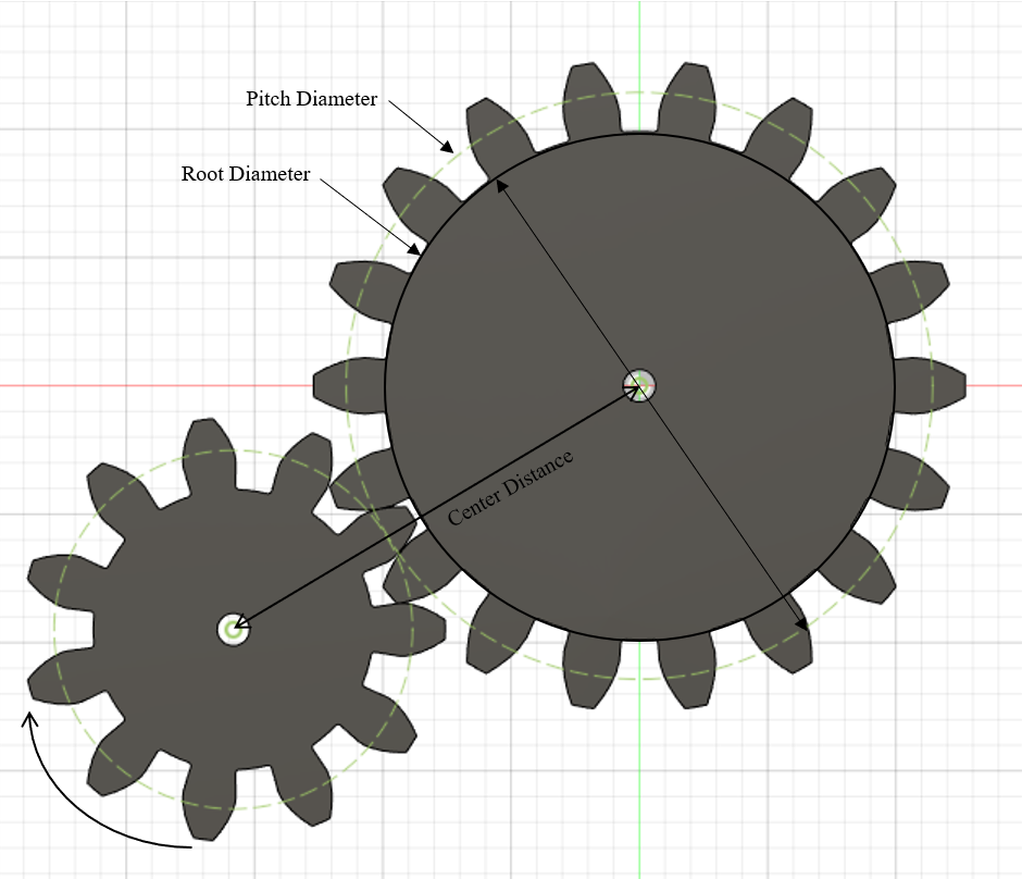
Moreover, bevel gears are always placed perpendicular in pairs. In general, it can be classified as a straight, spiral, or hypoid bevel gear. The shapes are similar to spur and helical parallel-placed gears. The main advantage of bevel gear application is to alter the direction of the rotation motion. Based on its application position, 3 directions of force are located in design, which is tangential, axial and radial force. Tangential force is along the pitch line that rotates the gears. Radial and Axial force acted radially to maintain the position of the bevel gears. The gear always occurs in the set. The rotating shaft activates the first gear, and then the rotation of the first gear transfers the motion and torque to nearby gear by their contacting teeth. Figure 1 below shows an example of spur gear. It is one of the most common gear types that could be found in geared mechanical products.
|
| |
Figure 1. Spur gears [3] | Figure 2. Gears application [3] |
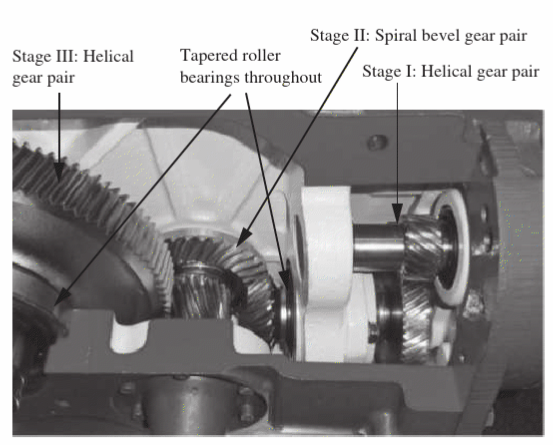
Various types of gear, such as spur gear, helical gear, bevel gear and worm gearing, can be applied in different circumstances to maximize the performance and minimize drawbacks. Figure 2 shows a design of combining different types of gears. The pinon helical gear smoothly carries the torque from the input transmitted to the paired helical gear in stage I. The bevel gear at stage II reduction receives the torque from stage I and transmits it to the large helical gear in stage III via a helical gear on the same shaft. Yielding the typical failure type of gear which is required to be considered. To avoid yielding, bending stress and contact stress are two factors that need to be aware of in the gear design. The bending stress of gears is associated with the bending moment in the gear rotation, and the contact stress is the general stress transmitting on the contact surface of teeth. Both of the two stresses are strongly related to the mass, size, rim thickness, input power, working load and gear modulus. The material and shape selection trend is significant to improve the strength and minimize yielding and failure [5].
2.2. Belt and chain
The belt and chain are different components but work with similar functions. They represent a flexible torque delivery method between input and output and are normally employed in a high-speed environment [3]. In the mainstream, belts are made from soft materials like leather and rubber. It is commonly wrapped on the input and output sheave for energy delivery. Initially, the belt is placed around two sheaves or pully when the distance between two sheaves is reduced. After placing the belt, the sheaves are moved to their original position with a high belt tension. The diameter of the sheaves D1 and D2 is defined as its pitch diameter.
Different types of belts could be used in different conditions. Flat belts, v-belts and synchronous belts are typical types of belts. One of the obvious advantages of the belt is that it can be applied with less or no lubrication condition, but the slipping is difficult to avoid in this case. Small pully size is the trend to cause a large slipping through testing [6]. The chains it is made of pin-connected links placed at the rotating sprockets. The application process is similar to the belt. Different from the belts, the slacked side is at the bottom, and the tight side is at the top. Compared with belts, the main benefit can be the higher efficiency with no slipping. However, the new disadvantages that chains can bring are noise and lubrication requirements.
3. Gears and belts/chain design
3.1. Gears
For Designing a gear transmission, various criteria need to be considered, including load/torque requirement, material selection, Geometry and tooth profile, Pitch diameter, Gear ratio, Noise and vibration. To figure out the bending and contact stress for material selection, the load and torque requirements are planned to be defined at the beginning. The diametral pitch and gear ratio need to be designed for further calculation using equations (1) and (2).
\( {P_{d}}=\frac{N}{D}\ \ \ (1) \)
\( Gear ratio={m_{G}}=\frac{{N_{G}}}{{N_{P}}}\ \ \ (2) \)
For equation (1), N is the number of teeth and D is the pitch diameter. For equation (2), NG is the teeth number of gear and NP is the teeth number of pinion.
For the bending stress, the Lewis equation (3) could be applied to the bending stress calculation with Lewis form factor (YN) and known tangential force (Wt), diametral pitch (Pd) and face width (F). The Lewis factor can be varied for the pressure angle, load position and the number of teeth, which means different types of gear could have different bending stress according to the AGMA standard.
\( {σ_{b}}=\frac{{W_{t}}{P_{d}}{K_{t}}}{FY}\ \ \ (3) \)
After the bending stress is determined safe, the contact stress should be considered to avoid the pitting phenomenon on gear teeth. The Hertz contact stress equation can be introduced as a conclusion of contact stress calculation [equation (4)].
\( {σ_{c}}={(\frac{{W_{c}}}{Fπ}\frac{1}{([\frac{1-v_{1}^{2}}{{E_{1}}}]+[\frac{1-v_{2}^{2}}{{E_{2}}}])(\frac{1}{{r_{1}}}+\frac{1}{{r_{2}}})})^{0.5}}\ \ \ (4) \)
This stress is related to the contact force (Wc), curvature radii (r), face width (F), tensile modulus of elasticity (E) and Poisson ratio (v).
American Gear Manufacturers Association (AGMA) suggests that the contact stress could be calculated at the lowest point of single-tooth contact with the elastic coefficient. However, the radii (r1 and r2) could change during the meshing cycle at the lowest point of a single tooth. This is relatively complex for the computation. The pitting geometry factor can be used to calculate the contact stress; the contact stress equation can be simplified as equation (5) [3].
\( {σ_{c}}={C_{P}}{(\frac{{W_{t}}}{F{D_{p}}I})^{0.5}}\ \ \ (5) \)
where I is the geometry factor of the gear and Cp is the simplified elastic factor.
Considering the realistic case of gear operation, the operational factors (AGMA provides a method that finds the values of factors) are introduced to the equation (5) to calculate the contact stress for contacting gear and pinion. In addition, the life hour of gears needs to be decided by the safety factor requirement, bending stress and contact stress, calculating the final allowable stress. The AGMA standard can be introduced for this calculation.
3.2. Factors of spur, helical gears and bevel gears
The Bending stress and contact stress of spur and helical gears could be computed by the same equation based on equation (4). According to the AGMA 2001-D04 Standard, equation (6) and (7) is applied for theoretical bending and contact stress number calculation with designed Cp, Wt, Pd, Kt, F, D and Y.
\( {s_{b}}=\frac{{W_{t}}{P_{d}}{K_{t}}}{FY}{K_{o}}{K_{s}}{K_{m}}{K_{v}}{K_{B}}\ \ \ (6) \)
\( {s_{c}}={C_{P}}{(\frac{{W_{t}}{K_{o}}{K_{s}}{K_{m}}{K_{v}}}{FDI})^{0.5}}\ \ \ (7) \)
The rim thickness factor (KB), dynamic factor (Kv), overload factors (Ko), load-distribution factor (Km) and size factor (Ks) are aimed to be considered in general spur and helical gear design. The ratio of rim thickness and the teeth height determines the backup ratio, which is related to the Rim thickness factor. The rim thickness factor tends to decrease with the backup ratio increase, and the rim thickness factor remains a value greater or equal to 1 for a high backup ratio [7]. The dynamic factor is weighting the additional impact that is greater than the theoretical load. The higher pitch line velocity is the trend to introduce a higher dynamic factor with different AGMA-quality number (Av), and the gears with higher Av has a higher dynamic factor at the same pitch line velocity. The overloading factors are associated with the operating and power shock level. A higher shock level could lead to a higher overloading factor [8]. The load distribution factor and Size factor are normally considered as 1.00 for reasonable design and production. They are associated with the application design of gears and the size of gears. These two factors could vary in a few cases with inappropriate installation and production of gears [3]. After determining the bending and contact stress, the final allowable strength calculation can be computed by stress cycle safety and decided factor by the equation (8). the stress cycle factor can be found with the designed lifetime based on the AGMA standard. The actual performance of spur and helical gear may be varied from the theoretical calculation. The computational analysis above could generally increase the accuracy of the allowable stress in design.
3.3. Belt design factors
The dimensions and the mechanical components design are generally based on the center distance and the belt angle of the belt/chain drive. The torque transmitted on the belt is associated with the slack side force, tight side force and the diameter of the sheave in equation (8). The pitch length L is strongly related to the center distance and the sheave diameters, which can be calculated based on the equation (9), (10) and (11). Moreover, the power rate could be calculated by equation (11) with the angle factor K, Basic power rating, and capacity of the speed ratio ∆PR and belt length ∆PL. In general, after considering the power rate and the dimension of the belt and chain, the overall allowable stress of the belt is based on the material yield strength in tension. This could be found out by using the material property chart.
4. Application of transmission
Based on the gear solution and the belt solution for the transmission, many different transmission solutions are applied in the modern mechanical industry. In the automobile industry, DCT and CVT are two main types that are widely applied in the latest models of German and Japanese cars. DCT transmission is basically designed to transmit power by a solid gear system. CVT applied the belt/chain structure for the power transmitting solution. In these application cases, the transmission is controlled by the electrically controlled unit that sends the command to clutch (DCT) or driving pully (CVT) to shift the transmitting ratio.
4.1. DCT
4.1.1. Description of DCT. DCT is designed according to the parallel shaft manual transmission of commercial vehicles. Two sets of gears are placed on different shafts connecting with two individual clutches, similar to combining two typical manual transmissions (Figure 3). The transmitting ratio is able to be changed by shifting the connection from the input shaft to each of the gear sets. The individual clutches are controlled by the electrical control system that could study the command to improve the shifting speed and shifting logic.
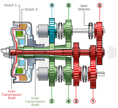
Figure 3. A structure example of DCT [9].
4.1.2. Advantages and disadvantages of DCT. Compared to the classic manual transmission, the DCT gearbox normally has a more available transmitting ratio, benefiting from the innovative gear-shifting design. The DCT gearbox also allows a high input power based on the gear transmission. The solid alloy gear is able to sustain a high load from the input, which increases the allowable working load. Moreover, the shifting speed to the DCT is generally excellent. The shocking acceleration and velocity in Figure 4 show a generally smooth operating status based on the study of DSG transmission [9]. However, with the high strength at the gear section, the clutch may not be able to sustain the load while shifting the gear sets. That could lead to the failure of the whole DCT system by breaking the clutch system. The material study shows that the strength increase for the clutch would significantly increase the cost of design and manufacturing. The weight of DCT is another disadvantage compared with other transmissions. The mass trend is big, with numerous metal and alloy gear components.
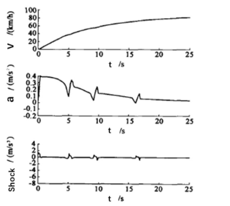
Figure 4. DSG DCT operation test result [9].
4.2. Continuously variable transmission
The CVT is designed based on the belt/chain transmission. It is suitable for high-speed operating conditions. The CVT transmits power efficiently via the continuous transmitting component, and it can be classified as belt CVT, Spherical CVT and chain CVT [10]. The electrical system controls the motion of the pully to vary belt movement to achieve the optimum transmitting ratio.
The continuously variable transmission generally has a higher efficiency that saves energy while operating. The transmitting ratio is infinite within the ratio range, which means CVT can reach the most optimum speed ratio while operating. The elimination of lost work via CVT is expected to increase the efficiency of the whole system significantly. Moreover, by using the belt/chain structure, the size and weight of the transmission can be minimized compared with the geared transmission. The space efficiency is expected to increase with CVT application. However, the maximum allowable stress is limited by the structure. The energy transmitted on CVT will directly act on the belt/chain structure, which introduces tension stress. As the flexibility of the belt and chain, the strength is expected to be lower compared with DCT. Increasing the strength of the belt/chain may be the only method to increase the maximum allowable stress currently.
5. Conclusions
The transmission is an important system for energy, speed and torque transmission in the current mechanical industry. The performance of the transmission is strongly related to its solution. The bending stress, contact stress, load, tension and power ratio are the significant factors for transmission design. Based on specific requirements, the gear and belt/chain solution can be designed considering the factors listed above. The DCT and CVT are the most common transmissions applied in vehicles with gear and belt/chain solutions. The High reliability of DCT is benefited by the gear solution, which can sustain a high operating stress. The limit of DCT could be the clutch system.
Moreover, CVT has a high energy efficiency while operating at various speeds. The limit of CVT could be the low strength of the flexible belt/chain material and design. In general, the transmission could be designed by the different operation conditions. Currently, the mechanical gear and belt/chain could be the widest applied structure of transmission. The combination of gear and belt/chain can be a good thought for further study. Friction and contact creeping could be the top concern of the structures mentioned. A more efficient structure may be possible to be developed, which minimizes the contact friction. The electrical-related structure and the magnetic structure may be the more advanced solutions for future design.
References
[1]. Aguilera J, Meesenburg W, Ommenm T, Markussen W, Poulsen J, Zühlsdorf B and Elmegaard B 2022 Renewable and Sustainable Energy Reviews 168 112826
[2]. Soleimanian S, Petrone G, Franco F, Rosa S and Kołakowski P 2023 Application of metal rubber for semi-active vibration control of mechanical transmission systems
[3]. Mott R 2016 Mech2100 Machine Design 319
[4]. Sarkar S, Nag A and Kumar R 2023 Renewable Energy Production and Distribution 2 249
[5]. Ashby M 2011 Materials Selection in Mechanical Design Fourth Edition 147
[6]. Balta B, Sonmez F & Cengiz A 2015 Mechanism and Machine Theory 86 1
[7]. Hiremagalur J and Ravani B 2004 Mechanics Based Design of Structures and Machines 423
[8]. Childs P 2014 Mechanical Design Engineering Handbook 423
[9]. Ye S 2022 Advances in Economics, Business and Management Research 217 1
[10]. Shukla P, Tiwari P, Singh Y, Singh V and Yadav R 2017 International Journal of Engineering Research & Technology 6 4
Cite this article
Liu,S. (2024). Common transmission theory and wide application. Theoretical and Natural Science,30,165-171.
Data availability
The datasets used and/or analyzed during the current study will be available from the authors upon reasonable request.
Disclaimer/Publisher's Note
The statements, opinions and data contained in all publications are solely those of the individual author(s) and contributor(s) and not of EWA Publishing and/or the editor(s). EWA Publishing and/or the editor(s) disclaim responsibility for any injury to people or property resulting from any ideas, methods, instructions or products referred to in the content.
About volume
Volume title: Proceedings of the 3rd International Conference on Computing Innovation and Applied Physics
© 2024 by the author(s). Licensee EWA Publishing, Oxford, UK. This article is an open access article distributed under the terms and
conditions of the Creative Commons Attribution (CC BY) license. Authors who
publish this series agree to the following terms:
1. Authors retain copyright and grant the series right of first publication with the work simultaneously licensed under a Creative Commons
Attribution License that allows others to share the work with an acknowledgment of the work's authorship and initial publication in this
series.
2. Authors are able to enter into separate, additional contractual arrangements for the non-exclusive distribution of the series's published
version of the work (e.g., post it to an institutional repository or publish it in a book), with an acknowledgment of its initial
publication in this series.
3. Authors are permitted and encouraged to post their work online (e.g., in institutional repositories or on their website) prior to and
during the submission process, as it can lead to productive exchanges, as well as earlier and greater citation of published work (See
Open access policy for details).
References
[1]. Aguilera J, Meesenburg W, Ommenm T, Markussen W, Poulsen J, Zühlsdorf B and Elmegaard B 2022 Renewable and Sustainable Energy Reviews 168 112826
[2]. Soleimanian S, Petrone G, Franco F, Rosa S and Kołakowski P 2023 Application of metal rubber for semi-active vibration control of mechanical transmission systems
[3]. Mott R 2016 Mech2100 Machine Design 319
[4]. Sarkar S, Nag A and Kumar R 2023 Renewable Energy Production and Distribution 2 249
[5]. Ashby M 2011 Materials Selection in Mechanical Design Fourth Edition 147
[6]. Balta B, Sonmez F & Cengiz A 2015 Mechanism and Machine Theory 86 1
[7]. Hiremagalur J and Ravani B 2004 Mechanics Based Design of Structures and Machines 423
[8]. Childs P 2014 Mechanical Design Engineering Handbook 423
[9]. Ye S 2022 Advances in Economics, Business and Management Research 217 1
[10]. Shukla P, Tiwari P, Singh Y, Singh V and Yadav R 2017 International Journal of Engineering Research & Technology 6 4