


1. Introduction
Being a popular element for artwork decorations, curves can express different senses by changing their thickness and degree of curvature. A mashup of curves can deliberately create harmonious symmetry which can help observers to find pleasing balance in images. Although a perfectly symmetrical pattern is hard to draw by hand, the spirograph is a useful geometric drawing device, with multiple uses like educational toys and creative design tools, to produce highly symmetrical roulette curves. Basically, the whole set is composed of an annulus with ridged edges and wheel gears with numerous little holes on them [1-6]. By putting a pen in one of the perforations on a wheel gear and rolling it around a fixed annulus, fascinating and aesthetic patterns can be generated. Although these patterns seem random and infinite, the concept behind the spirograph is rooted in a wide range of mathematical topics.
There are a number of studies that explore the mathematical connections with spirographs. William E. Cavanaugh investigated the relationship between the number of cusps of spirograph patterns and the Greatest Common Factors (GCD) of gear teeth numbers [2]. However, through this limited concept of GCD, a comprehensive mathematical explanation of its rationale was still not provided. Deck, Karin M then figured out the mathematical links to the spirograph in a more general way [1]. He presented the parametric equations of the coordinates of a tracing point on a spirograph. Although some specific key parameters of the spirograph pattern associated with the parameters were not dug deeper in the 1999 research, Ranjit Konkar analyzed certain special parameters according to predecessors’ research results, for example, the cusp connectivity [7]. This could significantly help people to recreate the formation of a spirograph. After understanding the theoretical principles, Bei Wang, Yuejie Geng and Jixun Chu explored spirograph’s applications in real life, like how the astroid, a specified curve in spirograph with unique characteristics, was used to reduce space when the bus doors opened [8].
During research, it can be found that the interactions between the parametric equations and possible key parameters of Spirograph patterns had rarely been systematically explained. Therefore, the purpose of this paper is to predict possible spirograph patterns, which will be achieved by deriving parametric equations and analyzing the key parameters. It is suggested that the position of perforations, number of teeth on two gears and position of start point are crucial factors. In addition, an interesting experiment about spirograph pattern design will be carried out. It will involve parametric-graphic interactions, which is to observe and analyze the features of a random spirograph and then estimate its parameters. It can not only prove the accuracy of the author’s previous conclusion but also help readers visualize this topic in a pellucid way.
2. The spirograph
2.1. 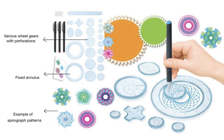 Origin and terminology of spirograph
Figure 1. Basic spirograph drawing set.
As shown in figure 1, the idea of spirograph was originally developed in the early 1960s by mechanical engineer Denys Fisher. This tool quickly soon became popular in the toy market, and new spirograph-related versions like the unusual shape deluxe set were updated continuously.
However, the curves in spirograph patterns were already given mathematical names before the invention of spirograph set. In around 1600, Gallileo Gallilei studied the ordinary cycloid in detail [1]. A cycloid is a curve traced by a point on the circumference of a circle being rolled along a straight line (Figure 2). In spite of its simple appearance, the fascinating properties of cycloid were used by the Romans in the ancient Greeks to shape the arches of bridged and aqueducts [9]. It also solved the famous brachistochrone problem, which was posed in 1696. The problem asked for the shape of the curve which joined two points at different elevations so that a dropping bead would reach the lower point in the least time [9]. The solution in fact was a segment of cycloid.
The cycloid is also called a common trochoid. Trochoid is the path of a point at a distance from the center of a circle rolling on a fixed line [7, 10]. To subdivide, if the chosen point is inside the rolling circle, the resulting curve is a curtate cycloid and if the chosen point lies outside the rolling circle, it is a prolate cycloid [7]. These types and variants are illustrated in Figure 2 for a circle rolling on a straight line.
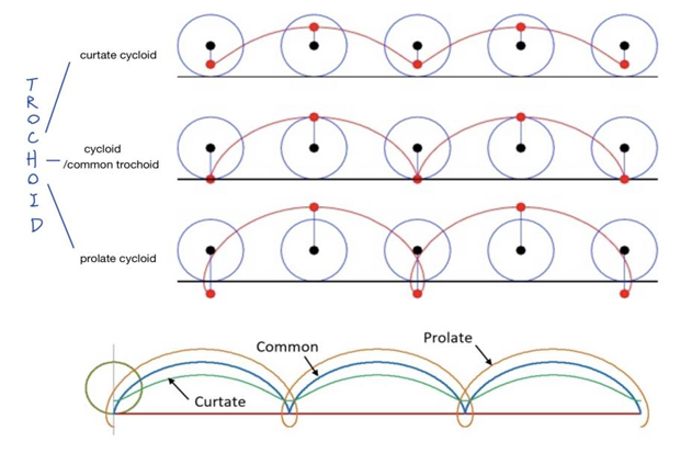
Figure 2. The formation of the curves of trochoids and cycloids.
Since the spirograph pattern is created by rolling one circle along another stationary circle instead of a straight line, different terminologies need to be given in order to describe such different formations. If the tracking point is on the boundary of a circle, the curve made by rolling the circle inside a fixed circle is called a hypocycloid (Figure 3a) [8, 11], which was first conceived by Roemer in 1674 while he was studying the best form of gear teeth, and the curve generated by rolling the circle outside a fixed circle is called epicycloid (Figure 3b) [11].
|
|
(a) | (b) |
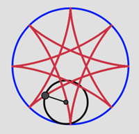
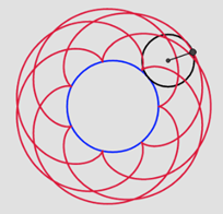
Figure 3. (a) Example graph of hypocycloid, (b) Example graph of epicycloid.
However, generally, the perforations in real spirograph set are usually located in the middle of the wheel gear rather than at the edge. In this condition, when the point is on the radius or extended radius but not on the circumference of the circle, rolling the circle inside a fixed circle results in a hypotrochoid (Figure 4a, 4b) [6]. Otherwise, the curve traced by a point on the radius or extended radius of a circle rolling on the outside of a fixed circle is called an epitrochoid (Figure 4c, 4d) [12].
|
|
|
|
(a) | (b) | (c) | (d) |
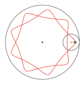
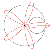
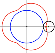
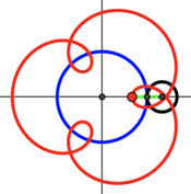
Figure 4. (a) A hypotrochoid with traced point on radius, (b) A hypotrochoid with traced point on extended radius, (c) An epitrochoid with traced point on radius, (d) An epitrochoid with traced point on extended radius.
Generally, if the tracing point is on the boundary of a circle, the curve formed by rolling the circle inside a fixed circle is called a hypocycloid, and the curve formed by rolling the circle outside a fixed circle is called an epicycloid. If the tracing point is on the interior or exterior of a circle, the curve is a hypotrochoid or epitrochoid.
However, there are some interesting special cases. For hypotrochoids, when the small circle is exactly half the size of the big one, the various spirograph patterns will become kind of simple [4]. An ellipse will appear at such time, and the greater the distance from the center of rolling circle to the point is, the pointier the ellipse is. This happens because the small circle completes a full turn each time it rolls around, so the line immediately matches again. Therefore, a single line will be produced when such a situation happens in hypocycloid.
For more variations, if the small circle remains stationary while a larger circle rolls around it in contact, like a hula-hoop, a point on the rolling circle will generate a peritrochoid [7]. In addition, it might be interesting that when there are two circles of equal radius, the formed epitrochoid is called Pascal Snail. One special case among the family of the snail is when the traced point lies on the circumference of the rolling circle. In this way, the resulting epitrochoid is the famous cardioid.
After classifying four types of spirograph, it is still unknown why even among the same type there are so many different patterns. In the next part, a formula that covers its principles of formations on different shapes will be investigated by using mathematical derivation and concepts about geometry and trigonometry.
2.2. Parametric equations of spirograph
2.2.1. Derivation. To obtain the equations that can describe spirograph curves, the type of equation required must be decided first. As shown in Figure 3 and Figure 4 (red curves), regarding the centers as origins, it is obvious that these curves fail the vertical line test. In other words, every vertical line does not intersect these curves in at most one point. Therefore, the spirograph curve cannot be simply represented as functions \( y=f(x) \) .
Moreover, it is obvious that the formation of a spirograph is composed of two movements: the rotation of the rolling circle and its revolution around the fixed circle, which makes different spirographs depending on the position of revolution. This can link to the combined movements in the projectile which include both horizontal and vertical directions. In these cases, it is convenient to consider x and y as functions of an independent variable t, known as a parameter. Through the introduction of the parameter, it is easier to describe the motion law in x and y directions [11]. For example, \( x=f(t) \) , \( y=g(t) \) . Together, this is called a parametric equation for a curve that is traced by changing the values of the parameter t. Therefore, the movements of rotation and revolution in spirograph can be described separately using a parameter, and then combined to obtain a final parametric equation.
In order to apply parametric equations to curves in spirograph patterns, parametrizing a circle is the first step because the curves are formed by the rotation of two circles. Circles have a Cartesian general equation:
\( {(x-a)^{2}}+{(y-b)^{2}}={r^{2}}\ \ \ (1) \)
for a circle with center \( (a,b) \) and radius r.
For parametrization, we use a circle whose center is origin (Figure 5). Assume point P ( \( rcos{θ} \) , \( rsin{θ} \) ) on the boundary of the circle. Put the value \( x=rcos{θ}, y=rsin{θ} \) in \( {x^{2}}+{y^{2}}={r^{2}} \) and simplify, it is found that \( x=rcos{θ}, y=rsin{θ} \) are the parametric form of the equation of the circle, regarding θ as the parameter.
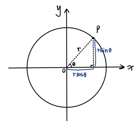 Figure 5. A circle with center in origin and radius of r.
Since the spirograph patterns basically have four types: hypocycloid, epicycloid, hypotrochoid, and epitrochoid, there must be four parametric equations to generalize each of them.
Figure 6 illustrates the construction of a hypocycloid. Establish a Cartesian system with point O as the origin, denote radius of the fixed circle O by R, radius of the rolling circle Q by r, and the degree of rotation of the center of the rolling circle Q by θ. Since the trace of the center of circle Q is a circle with radius R-r, the parametric equations of this circle (in red dashed line) are:
\( x=(R-r)cos{θ} \) | (2) |
\( y=(R-r)sin{θ} \) |
The parametric equations of hypocycloid are determined by the coordinates of the tracing point P, so denote the orientation of the circle Q after it rolled by α. The coordinates of the tracing point P are:
\( x=(R-r)cos{θ}+rcos{α} \) | (3) |
\( y=(R-r)sin{θ}+rsin{α} \) |
Then, when circle Q rolls inside around circle O, it can be noticed that the arc length of every point on circle O that has been in contact with the circle Q equals the arc length of every point on the circle Q that has been in contact with circle O. Therefore, the relationship between α and θ can be seen:
\( {P_{1}}T={P_{2}}T→ Rθ=(2π-α+θ)r → α=2π-(\frac{R}{r}-1)θ\ \ \ (4) \)
According to coterminal angles, angle α and angle \( (1-R/r)θ \) have the same initial and terminal sides, therefore:
\( α=-(\frac{R}{r}-1)θ\ \ \ (5) \)
Substitute α with θ to express coordinates of P. To simplify, as cosine functions are even and sine functions are odd, it can be deduced that the parametric equations of hypocycloid are:
\( x=(R-r)cos{θ}+rcos{((\frac{R}{r}-1)θ)} \) \( y=(R-r)sin{θ}-rsin{((\frac{R}{r}-1)θ)} \) | (6) |
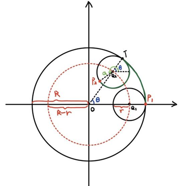
Figure 6. Construction of a hypocycloid.
Parametric equations for the other three types of spirograph patterns are similar to those above. For epicycloids, as shown in Figure 7, the main difference between epicycloid and hypocycloid is that the rolling circle is placed outside the fixed circle. Hence, the distance from origin to the distance from the center of circle Q is R+r. Due to the opposite direction of orientation, the plus sign turns to a minus sign. The coordinates of tracing point P become:
\( x=(R+r)cos{θ}-rcos{α} \) | (7) |
\( y=(R+r)sin{θ}-rsin{α} \) |
For the relationship between α and θ:
\( {P_{1}}T={P_{2}}T→ Rθ=(α-θ)r → α=(\frac{R}{r}+1)θ\ \ \ (8) \)
Therefore, the parametric equations for epicycloid are:
\( x=(R+r)cos{θ}-rcos{((\frac{R}{r}+1)θ)} \) \( y=(R+r)sin{θ}-rsin{((\frac{R}{r}+1)θ)} \) | (9) |
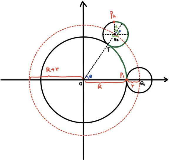 Figure 7. Construction of an epicycloid.
However, the tracing point is not always on the boundary of the rolling circle, which means the distance from the tracing point to the center of the rolling circle is not always r. Consequently, the only change in the parametric equations for the hypotrochoid and epitrochoid is the factor on their second terms. Let h be the factor, which indicates the distance between the tracing point and the center of the rolling circle. Then the parametric equations for hypotrochoid are:
\( x=(R-r)cos{θ}+hcos{((\frac{R}{r}-1)θ)}) \) \( y=(R-r)sin{θ}-hsin{((\frac{R}{r}-1)θ)}) \) | (10) |
Similarly, for epitrochoid, the parametric equations are:
\( x=(R+r)cos{θ}-hcos{((\frac{R}{r}+1)θ)}) \) \( y=(R+r)sin{θ}-hsin{((\frac{R}{r}+1)θ)}) \) | (11) |
2.2.2. Verification. To verify the accuracy of these four parametric equations, they are sequentially input into Desmos to compare the presented patterns with the actual situations. As shown in Figure 8, the equations are valid.
|
|
|
|
(a) | (b) | (c) | (d) |
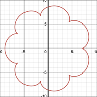
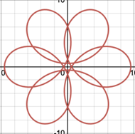
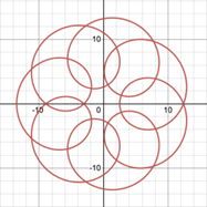
Figure 8. Spirograph patterns in Desmos, (a) A hypocycloid with R=7, r=1, (b) An epicycloid with R=7, r=1, (c) A hypotrochoid with R=6, r=1, h=4.5, (d) An epitrochoid with R=7, r=1, h=5.5.
2.2.3. Discussion of parameters r and h. Looking at Figure 6 and Figure 7 and considering the formation process of four types of spirographs, spirographs can be regarded as subtracting or adding parts of a smaller circle from a larger circle. In Formula 1, 2, 3 and 4 above, the front part represents the larger circle, and the back part represents the smaller circle. Therefore, if the coefficient of the part of the smaller circle (which can be r or h depending on different types) is large, it means that more things are subtracted or added from the original large circle, then the remaining pattern will relatively fluctuate more. Conversely, if r or h is small, the resulting pattern will fluctuate less and tend to be close to circle. This is related to Figure 8 and can be seen by comparing the four graphs.
2.2.4. Identification of spirograph types through resulting figures. In addition to distinguishing types by drawing process, the law of directly identifying the type through the resulting figures can be derived, by summarizing above and more figures.
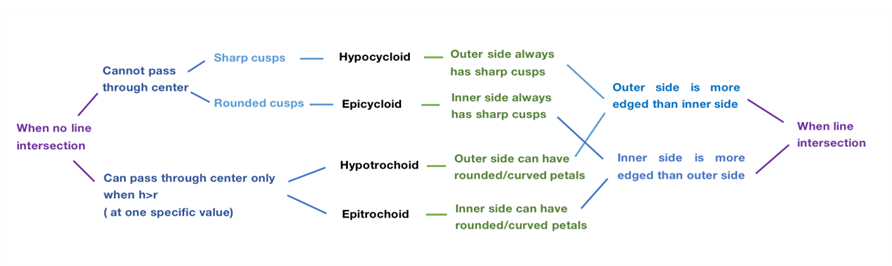
Figure 9. Identification methods of spirograph types through features in resulting figures.
For identification methods in Figure 9, when there is no line intersection in the resulting pattern, the features of sharp and rounded cusps are regarded as hypocycloids and epicycloids respectively, without passing through the center. Meanwhile, the situation of no line intersection only happens on hypotrochoids and epitrochoids at one specific value when h>r, with a line passing through the center, while hypotrochoids have edged petals on the outer side and epitrochoids have smooth outer side like a circle. When there are line intersections, the features of a more edged outer side than the inner side lead to hypocycloids and hypotrochoids, while the features of a more edged inner side than the outer side cause epicycloids and epitrochoids. To distinguish further, in hypoicycloids, the outer side always has sharp cusps, whereas in hypotrochoids, the outer side can have curved petals. Similarly, in epicycloids, the inner side always has sharp cusps, in contrast to the curved petals on the inner side in epitrochoids.
|
|
(a) | (b) |
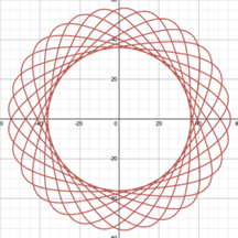
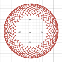
Figure 10. Two more complicated spirograph patterns, (a) A hypotrochoid, (b) An epicycloid.
To apply the methods, according to the pattern in Figure 10 a, it has a more edged outer side than the inner side, so it is either a hypocycloid or a hypotrochoid. It can be discovered that it has rounded petals on the outer side, therefore, this pattern is a hypotrochoid. Regarding the pattern in Figure 10b, its inner side is more edged than the outer side, as well as the sharp cusps on the inner side. Therefore, this pattern is an epicycloid.
In the next section, different parameters will be discussed so that the rules which determine the specific appearance of the graph can be discovered.
2.3. Key parameters of Spirograph
By deriving parametric equations of spirographs and applying them in drawing software, the essential key parameters of spirographs can be deduced according to the parameters.
In physical spirograph sets, the assumption is that possible key parameters might be the position of perforations, the position of starting point, and the number of teeth on the ring and the gear.
2.3.1. Position of perforations. Firstly, the position of perforations in related to factor h in the equations for hypotrochoids and epitrochoids. This key parameter will affect curvature of the spirograph patterns [7]. By varying h only in Desmos (Figure 11), it can be seen that the cusps of spirograph patterns retract inward and become more rounded as h decreases while not exceeding r. This means that if the perforation is closer to centre of the gear, the pattern looks more like a circle, and the equations result in exactly a circle if the perforation is at the center [1]. Furthermore, when the tracing point is placed at extended radius of the gear which cannot be simulated by physical spirograph sets, the greater h is, the more rings are formed and the more complex the pattern.
|
|
|
|
(a) | (b) | (c) | (d) |
|
|
|
|
(e) | (f) | (g) | (h) |
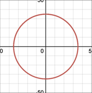
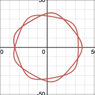
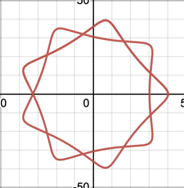
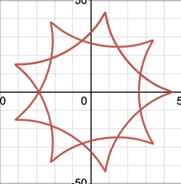
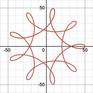
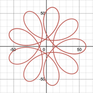
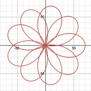
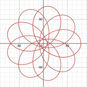
Figure 11. Variation of h in a hypotrochoid R=45, r=10, (a) h=0, (b) h=2, (c) h=5, (d) h=9, (e) h=15, (f) h=25, (g) h=35, (h) h=44.
Apart from the differences between the graphs in Figure 11, it is noticeable that the number of petals or the lines of symmetry are always the same as long as R and r are constant. Therefore, the position of perforation affects the curvature and complexity of spirograph patterns, while it does not impact the number of cusps in patterns.
2.3.2. Position of starting point. Secondly, by gradually restoring the spirograph’s formation from different starting points as shown in Figure 12, it can be discovered that no matter where to start, as long as all other conditions remain the same, the resulting patterns will be the same. As a result, the position of starting point tends to have no influence on spirograph patterns, because the patterns are always closed graphs.
Besides, the graph closes when the ratio of the number of teeth of the ring and the gear is a rational number. If the ratio is irrational like \( π \) , the curve will continue infinitely. This will be discussed in detail in part 2.3.4.
|
|
|
|
(a) | (b) | (c) | (d) |
|
|
|
|
(e) | (f) | (g) | (h) |
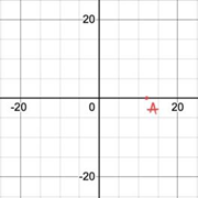
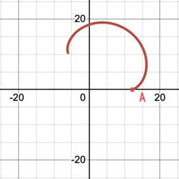
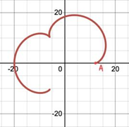
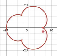
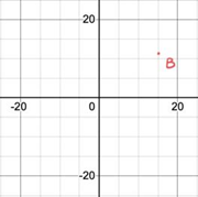
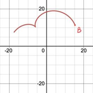
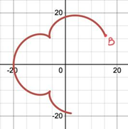
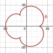
Figure 12. (a-d) The processes of formation of a pattern starting at point A, (e-f) The processes of formation of the same pattern starting at point B.
2.3.3. Number of teeth. Thirdly, in the derivation of parametric equations, the radius of circles is crucial data. In a spirograph set, devices have teeth instead of smooth edges in order to keep pen stationary during rotation and stop it sliding. In particular, each gear and ring are numbered according to the number of teeth around it. As it turns out, there are 30 teeth for each millimeter of the radius [1]. Hence, the ratio of radius (R/r) will be the same as the ratio of number of teeth. As shown in Figure 13, regardless of magnitude, the pattern will present the same as long as the M/N is constant. Therefore, the ratio of teeth number in ring and gear is a significant key parameter rather than their teeth number respectively.
|
|
(a) | (b) |
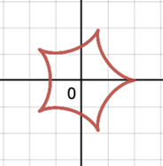
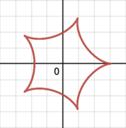
Figure 13. (a) A hypocycloid with R=10, r=8, (b) A hypocycloid of R=30, r=24.
In addition, another thing can be discovered that if the ring has m teeth, the hypocycloid formed with a gear of k teeth has the same shape as the hypocycloid formed with a gear of (m-k) teeth, which is the double generation theorem [13]. By investigating this property, it can be found that when the ring has m teeth, every epicycloid formed with gear of k teeth can be generated as a hypocycloid formed with gear of (m+k) teeth, which is not practical through physical sets.
Overall, the position of perforations and ratio of teeth number of rings and gears are the main key parameters of spirograph patterns and are also called outer parameters, which are similar to independent variables and can directly determine patterns’ shapes. There are also some features of the patterns that depend on outer parameters, which are called inner parameters [14]. They are the main characteristics in patterns like dependent variables, which are affected by in independent variables. For example, the number of cusps on the pattern and the angle between two consecutive cusps.
2.3.4. Number of cusps in relation to ratio of teeth. Cusps are significant characteristics of a spirograph pattern, and this part will focus on the relationship between the number of cusps and outer parameters. According to part 2.3.1, it is proved that pen point distance on gear has no effects on cusps number. Regarding Figure 13 in part 2.3.3, it can be found that the designs have five cusps when R/r is 5/4. As R/r equals ring teeth over gear teeth, one can predict what the resulting designs look like by using the reduced fraction of number of teeth (M/N).
By looking at patterns in Figure 14 and comparing their cusps and reduced fractions of number of teeth, it can be seen that number of cusps is the reduced numerator [1].
|
|
|
(a) | (b) | (c) |
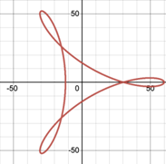
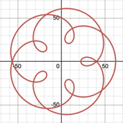
Figure 14. Different patterns drawn by different M/N, (a) 54/18=3/1, (b) 30/12=5/2, (c) 96/60=8/5.
Then, in order to analyze the significance of the reduced denominator, one might look at the number of revolutions of the rolling gear until it traces out all cusps. In Figure 15, for a pattern with M/N=11/2, the rolling circle completes two revolutions when it produces the resulting pattern, which indicates that the number of revolutions needed for the trace to meet its starting point is the reduced denominator [15-16].
|
|
|
(a) | (b) | (c) |
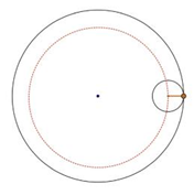
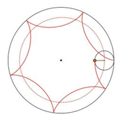
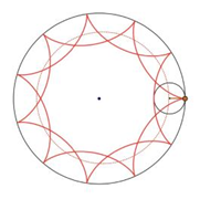
Figure 15. The process of formation of a spirograph pattern when its M/N=11/2, (a) At staring point, 0 revolution, (b) 1 revolution, (c) Meet the starting point, 2 revolution.
Overall, denote the most reduced form of ring teeth over gear teeth by M/N where M>N, the resulting spirograph pattern will have M cusps and is formed by N complete revolutions.
Consequently, by considering this rule, the larger N is, the more revolutions are needed, the more crowded pattern becomes. So it is clear that to form a closed spirograph, the number of revolutions must be finite, which means M/N must be a rational number that can be expressed as a fraction. When M/N has no finite fractional representation (such as \( π \) ) M and N have no least common multiple, the revolution and rotation will not meet at the same point once they start [7]. Therefore, when M/N is irrational, the spirograph pattern will be endless.
Meanwhile, using quantitative analysis, the relationship between M/N and the number of rotations of larger and smaller circles can be discovered. Denote number of teeth of larger and smaller circles by M and N respectively. In order to go back to the starting point at the same time, they both have to turn an integer cycle. Although they have the same linear velocity (assume 1 tooth per second), they have different angular velocity:
\( {ω_{M}}= \frac{360}{M} °/s\ \ \ (12) \)
Let T be the time when the larger and smaller circle meet at the starting point at the same time for the first time:
\( {T∙ω_{M}}= integer,{T∙ω_{N}}= integer, → T = lcm (M, N)\ \ \ (13) \)
Where lcm (a,b) represents the least common multiple of integer a and b [17]
Therefore:
\( {T∙ω_{M}}= N periods\ \ \ (14) \)
The reduced fraction M/N hence means: M is the number of rotations of the smaller circle, while N is the number of rotations of the larger circle.
2.3.5. Cusp connectivity in relation to ratio of teeth. In Figure 16, every pattern has 7 cusps as their numerators of the reduced fraction are all 7. When the denominator is 2 (Figure 16b), there must be 2 revolutions to produce complete pattern and this will introduce 1 more cusp equally spaced between the cusp 1, 3, 5, 7 formed during the first revolution. As a result, M/N=7/2 will cause a cusp connectivity of 1-3-5-7-2-4-6-1, which in other words is that every second one of the 7 points is linked, in contrast to 1-2-3-4-5-6-7-1 when M/N=7/1 (Figure 16a) and 1-4-7-3-6-2-5-1 when M/N=7/3 (Figure 16c).
|
|
|
|
(a) | (b) | (c) | (d) |
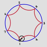
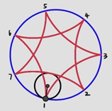
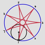
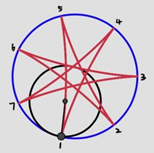
Figure 16. Spirograph patterns of 7 cusps, but connected differently, (a)M/N=7/1, (b) M/N=7/2, (c) M/N=7/3, (d) M/N=7/4.
In addition, by applying the double generation theorem mentioned at front in this part, M/N=7/3 will produce the same curves as M/N=7/4 (Figure 16d), and so do M/N=7/1 and M/N=7/6, except with tracing order reversed (for example, α = 7/4 will produce a connectivity 1–5–2–6–3–7–4–1). Such similar curves are called congruent [7].
Overall, by generalizing this finding, another significance of the reduced denominator can be expressed: Given M/N where M and N are mutually prime, the spirograph pattern produced will have M cusps in which every cusp is connected to Nth one sequentially during revolutions [7]. Meanwhile, this rule is helpful during the reverse identification which is to determine parameter M/N through the given spirograph pattern. And this will be mentioned in the next part which will focus on pattern design using parametric-graphic interactions.
2.4. Spirograph pattern design
Looking at Figure 17, this spirograph pattern can be regarded as a hypotrochoid according to the identification method mentioned in 2.2.4.
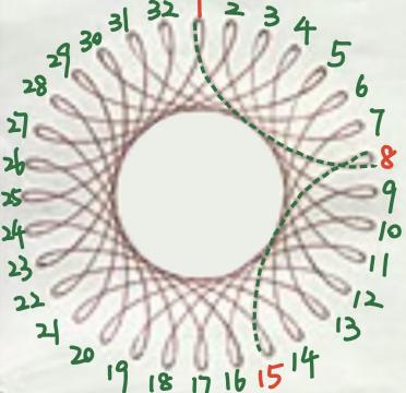 Figure 17. A random spirograph pattern chosen from the Internet.
For the number of teeth which is a key parameter, by observing its features, it can be seen that it has 32 cusps, and every cusp is connected to the 7th one. According to the rules mentioned in 2.3.4 and 2.3.5, the M/N is 32/7 or 32/25. This means that the ring teeth number can be 32k, and the gear teeth number can be 7k or 25k, for a positive integer k.
Moreover, for the position of perforations which is the other key parameter, it is important to estimate the factor h. It can be seen that the cusps of this pattern kind of extend outward and are less rounded compared to a circle. Hence, according to the rule mentioned in 2.3.1, h should be relatively large but still smaller than r, which means the chosen pen hole on the gear should be farther from the center.
Therefore, after determining the parameters, this pattern can be drawn through a physical spirograph set. For the equipment shown in Figure 18a, the ring with 96 teeth and the gear with 75 teeth are chosen (k=3), and the hole1 that has the largest distance to the center is chosen. Figure 18b is a final drawn image and it is very similar to the sample spirograph pattern.
|
|
|
(a) | (b) | (c) |
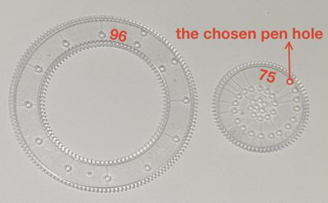
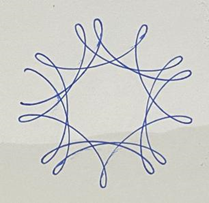

Figure 18. (a) The ring, gear and pen hole required to draw the image, (b) The process image, (c) The drawn image.
Figure 19 is a very different and more complex spirograph pattern from Figure 17. It includes four closed curves. According to the identification method mentioned in 2.2.4, all four curves can be regarded as hypotrochoids.
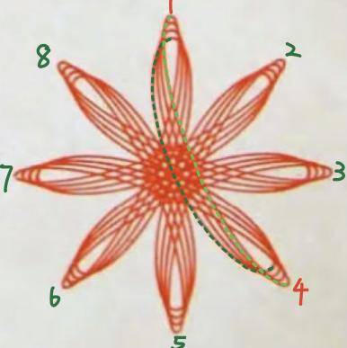 Figure 19. Another random spirograph pattern chosen from the Internet.
By observing features of this pattern, curves all have 8 cusps, and every cusp is connected to the 3rd one. Therefore, for the teeth number, all four curves are formed by the same ring and gear. By applying rules summarized in 2.3.4 and 2.3.5, the M/N should be 8/3 or 8/5, so the ring teeth number can be 8k, and the gear teeth number can be 3k or 5k, for a positive integer k.
The only difference between the four curves is their curvature, which is that the outermost curve is the sharpest and the closer the curves are to the center, the more rounded they are. Therefore, for the position of perforations, the h of these curves is different, and this means the pen should be placed at different holes each time. According to rule mentioned in 2.3.1, the outermost curve has the largest h, and the closer the curve is to the center, the smaller its h value.
As a result, for the drawing process, the required equipment is illustrated in Figure 20a. The ring has 96 teeth and the gear has 60 teeth (k=12), while the pen holes required for the curves from the outside to the inside are 1, 3, 5, 7 respectively (closer to the center). Figure 20b is the final drawn image and it also has high similarity with the sample.
|
|
|
(a) | (b) | (c) |
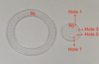
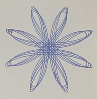
Figure 20. (a) The ring, gear and pen holes required to draw the image, (b) The process image, (c) The drawn image.
Overall, the experiment of pattern design indicates that theoretically, according to the given spirograph pattern, the corresponding parameters can be found and the similar image can be drawn by hand.
3. Conclusion
Spirograph is a popular drawing tool and the resulting various and seemly infinite patterns have aroused interests of exploring its formation and pattern prediction. Hence, the research is aimed to analyze the key parameters of spirograph using parametric equations and design spirograph patterns through parametric-graphic interactions.
Through literature, the spirographs can be classified into hypocycloid, epicycloid, hypotrochoid and epitrochoid based on their formation, according to the position of the tracing point and whether the small circle rolls inside or outside the fixed circle. To link this with resulting patterns, identification methods of spirograph types through patterns’ features is introduced in this paper. The parametric equations of four types of spirograph are also derived. It is clear that in the equations of hypocycloids and hypotrochoids, the x value consists of the addition of two monomials and the y value consists of the subtraction of two monomials; while both x and y values in parametric equations of epicycloids and epicycloids are composed of subtraction of two monomials. Through further analysis, the key parameters that determine spirograph patterns are position of perforations and the ratio of teeth number of the gear and ring. The former only affects its curvature, indicating the cusps of spirograph patterns will be more rounded when the pen hole becomes closer to the center, and the latter impacts the number of cusps and the cusp connectivity, which are presented by the reduced numerator and denominator respectively. Therefore, in pattern design, the combination of the number of cusps and cusp connectivity should be considered first to pick the ring and gear with the proper teeth number, and the degree of curvature of cusps can help to choose appropriate pen holes.
This paper thoroughly investigates and explains the impacts of spirographs’ key parameters and it combines parameters and graphs to predict and design spirographs, which can help designers draw the complex spirographs they have in mind more precisely. However, there are still some limitations. Firstly, the feature-related type identification method could involve quantitative and pithier metrics rather than basic observation. For instance, numerical parameters can appear in type identification so that this process can be simplified and become easier to use. Also this paper is based on the ideal situation that the pen holes on gears are just a point, but in reality they are tiny circles. Hence the radius of perforations should be considered as well. In addition, since the pen holes on gears are fixed and arranged with equal distance in spirals, the change in patterns’ curvature according to position of each hole can be further explored. Because otherwise repetition of drawing in different holes and then comparison is the only possible option to obtain the expected spirograph while designing.
Additional research could focus on the definition expression of curvature combined with parametric equations to study the change of curvature in the trajectory of spirographs, which not only improves the aspect of quantitative analysis but also provides more accurate data to electronic visualization of spirograph formation as well as its pattern design.
References
[1]. Deck, K. M. (1999). Spirograph® Math. Humanistic Mathematics Network Journal, 1(19), 7.
[2]. Cavanaugh, W. E. (1975). The Spirograph and the Greatest Common Factor. The Mathematics Teacher, 68(2), 162-163.
[3]. Stender, P. SPIROGRAPH–A TOY AS A MATHEMATICAL PROBLEM. Including the Highly Gifted and Creative Students–Current Ideas and Future Directions, 347.
[4]. Lessley, M., & Beale, P. (2012, July). Projecting Mathematical Curves with Laser Light. In Proceedings of Bridges 2012: Mathematics, Music, Art, Architecture, Culture (pp. 557-560).
[5]. Saunders, R., & Gero, J. S. (2001). A curious design agent. In CAADRIA (Vol. 1, pp. 345-350).
[6]. Etemad, K., Carpendale, S., & Samavati, F. (2014, August). Spirograph inspired visualization of ecological networks. In Proceedings of the Workshop on Computational Aesthetics (pp. 81-91).
[7]. Konkar, R. (2022). Flattening the curve... of Spirographs. Recreational Mathematics Magazine, 9(16), 1-20.
[8]. Wang, B., Geng, Y., & Chu, J. (2019, November). Generation and application of hypocycloid and astroid. In Journal of Physics: Conference Series (Vol. 1345, No. 3, p. 032085). IOP Publishing.
[9]. Shell-Gellasch, A. (2015). The Spirograph and Mathematical Models from 19th-Century Germany. Math Horizons, 22(4), 22-25.
[10]. Whitaker, R. J. (2001). Harmonographs. ii. circular design. American Journal of Physics, 69(2), 174-183.
[11]. Ippolito, D. (1999). The mathematics of the spirograph. The Mathematics Teacher, 92(4), 354-358.
[12]. Hall, L. M. (1992). Trochoids, roses, and thorns—beyond the spirograph. The College Mathematics Journal, 23(1), 20-35.
[13]. Flores, A., Prichard, M. K., Bezuk, N., & Moody, M. (1992). Activities: Mathematical Connections with a Spirograph. The Mathematics Teacher, 85(2), 129-137.
[14]. Lin, Y., & Vuillemot, R. (2013, October). Spirograph designs for ambient display of tweets. In IEEE VIS 2013. IEEE.
[15]. Gerofsky, S., Gomez, F., Rappaport, D., & Toussaint, G. (2009, July). Spirograph patterns and circular representations of rhythm: Exploring number theory concepts through visual, tangible and audible representations. In Proceedings of Bridges 2009: Mathematics, Music, Art, Architecture, Culture (pp. 279-286).
[16]. Kang, R., Johnson, S., Lambert, E., & Davidson, C. (2020). Doing Mathematics with Spirograph. Mathematics Teacher: Learning and Teaching PK-12, 113(11), 895-903.
[17]. Sayers, N. (2018, July). The Art and Mathematics of Cycling: Using Old Bicycles to Draw Spirograph Patterns. In Proceedings of Bridges 2018: Mathematics, Art, Music, Architecture, Education, Culture (pp. 455-458).
Cite this article
Li,W. (2023). Analytical study of spirograph using parametric equations and pattern design by parametric-graphic interactions. Theoretical and Natural Science,10,64-78.
Data availability
The datasets used and/or analyzed during the current study will be available from the authors upon reasonable request.
Disclaimer/Publisher's Note
The statements, opinions and data contained in all publications are solely those of the individual author(s) and contributor(s) and not of EWA Publishing and/or the editor(s). EWA Publishing and/or the editor(s) disclaim responsibility for any injury to people or property resulting from any ideas, methods, instructions or products referred to in the content.
About volume
Volume title: Proceedings of the 2023 International Conference on Mathematical Physics and Computational Simulation
© 2024 by the author(s). Licensee EWA Publishing, Oxford, UK. This article is an open access article distributed under the terms and
conditions of the Creative Commons Attribution (CC BY) license. Authors who
publish this series agree to the following terms:
1. Authors retain copyright and grant the series right of first publication with the work simultaneously licensed under a Creative Commons
Attribution License that allows others to share the work with an acknowledgment of the work's authorship and initial publication in this
series.
2. Authors are able to enter into separate, additional contractual arrangements for the non-exclusive distribution of the series's published
version of the work (e.g., post it to an institutional repository or publish it in a book), with an acknowledgment of its initial
publication in this series.
3. Authors are permitted and encouraged to post their work online (e.g., in institutional repositories or on their website) prior to and
during the submission process, as it can lead to productive exchanges, as well as earlier and greater citation of published work (See
Open access policy for details).
References
[1]. Deck, K. M. (1999). Spirograph® Math. Humanistic Mathematics Network Journal, 1(19), 7.
[2]. Cavanaugh, W. E. (1975). The Spirograph and the Greatest Common Factor. The Mathematics Teacher, 68(2), 162-163.
[3]. Stender, P. SPIROGRAPH–A TOY AS A MATHEMATICAL PROBLEM. Including the Highly Gifted and Creative Students–Current Ideas and Future Directions, 347.
[4]. Lessley, M., & Beale, P. (2012, July). Projecting Mathematical Curves with Laser Light. In Proceedings of Bridges 2012: Mathematics, Music, Art, Architecture, Culture (pp. 557-560).
[5]. Saunders, R., & Gero, J. S. (2001). A curious design agent. In CAADRIA (Vol. 1, pp. 345-350).
[6]. Etemad, K., Carpendale, S., & Samavati, F. (2014, August). Spirograph inspired visualization of ecological networks. In Proceedings of the Workshop on Computational Aesthetics (pp. 81-91).
[7]. Konkar, R. (2022). Flattening the curve... of Spirographs. Recreational Mathematics Magazine, 9(16), 1-20.
[8]. Wang, B., Geng, Y., & Chu, J. (2019, November). Generation and application of hypocycloid and astroid. In Journal of Physics: Conference Series (Vol. 1345, No. 3, p. 032085). IOP Publishing.
[9]. Shell-Gellasch, A. (2015). The Spirograph and Mathematical Models from 19th-Century Germany. Math Horizons, 22(4), 22-25.
[10]. Whitaker, R. J. (2001). Harmonographs. ii. circular design. American Journal of Physics, 69(2), 174-183.
[11]. Ippolito, D. (1999). The mathematics of the spirograph. The Mathematics Teacher, 92(4), 354-358.
[12]. Hall, L. M. (1992). Trochoids, roses, and thorns—beyond the spirograph. The College Mathematics Journal, 23(1), 20-35.
[13]. Flores, A., Prichard, M. K., Bezuk, N., & Moody, M. (1992). Activities: Mathematical Connections with a Spirograph. The Mathematics Teacher, 85(2), 129-137.
[14]. Lin, Y., & Vuillemot, R. (2013, October). Spirograph designs for ambient display of tweets. In IEEE VIS 2013. IEEE.
[15]. Gerofsky, S., Gomez, F., Rappaport, D., & Toussaint, G. (2009, July). Spirograph patterns and circular representations of rhythm: Exploring number theory concepts through visual, tangible and audible representations. In Proceedings of Bridges 2009: Mathematics, Music, Art, Architecture, Culture (pp. 279-286).
[16]. Kang, R., Johnson, S., Lambert, E., & Davidson, C. (2020). Doing Mathematics with Spirograph. Mathematics Teacher: Learning and Teaching PK-12, 113(11), 895-903.
[17]. Sayers, N. (2018, July). The Art and Mathematics of Cycling: Using Old Bicycles to Draw Spirograph Patterns. In Proceedings of Bridges 2018: Mathematics, Art, Music, Architecture, Education, Culture (pp. 455-458).