


1. Introduction
As of the 21st century, research on supersonics for commercial aircraft since the 1950s has culminated in several designs of commercial supersonic aircraft. Recent advancements focus on the design concepts, design amendments or construction of said aircrafts. After the Concorde era, the United States currently leads the world in terms of commercial supersonic flight, with its X-59 low-boom research aircraft. Although many companies’ test and release schedules for their supersonic aircrafts have been pushed back, demands and orders for them remain. Nevertheless, no real commercial supersonic aircraft has entered the market since Concorde. The desire for faster travel across long distances fuels the interest and development in this field. High greenhouse gas emissions and noise levels are the environmental concerns at the forefront. Meanwhile, fuel efficiency, safety, size, and speed compose the other important factors of viability and attractivity of commercial supersonic flight. Considering the scientific and engineering advances made, this paper aims to reexamine and update on the challenges faced and solutions considered in regard to the feasibility of commercial supersonic flight in terms of noise. This is put in context of the Federal Aviation Administration regulations that currently prohibit civil aircrafts to be flown at a speed of Mach 1 or higher over land, which are likely to be amended to limit and not prohibit civil supersonic flight in relation to noise and emissions. As such, this study summarizes the current and future promising methods of resolving the sonic boom as well as the jet exhaust noise issue, allowing companies or independent researchers interested in this domain to obtain directions for further research.
2. Sonic boom mitigation
2.1. Principle of sonic booms
Firstly, an understanding of the basic principles and characteristics surrounding sonic booms in terms of the units associated with them, N-waves, and the factors governing their intensity is necessary. As an object moves through the air, it creates a series of pressure waves in front and at the back of itself in relation to the direction it is moving in, like the wake a boat leaves in water. However, when the object moves fast enough, reaching the speed of sound, the air’s behaviour resembles more that of a compressible fluid over one that is incompressible. The introduction of the term overpressure, defined as the pressure value above normal atmospheric pressure in that area, facilitates the following explanation. An object traveling at sonic or supersonic speeds leads to a buildup of pressure at the front of the object, a positive overpressure. The pressure decreases along the horizontal direction, reaching a level below the atmospheric pressure at the tail end of the object, a negative overpressure. The subsequent graphing of an overpressure profile forms the characteristic N-wave. A sudden change in pressure causes what is known as a sonic boom. N-waves thus cause two sonic booms, one due to the rise in pressure at the front of the aircraft and one at the end when the pressure returns to atmospheric. When the aircraft is manoeuvring, the overpressure profile may look different, forming a common U-shape. The peak pressure is dependent on the aircraft size and weight. However, the loudness of a sonic boom perceived by the human ear relies on the rise time of the pressure, on the suddenness of the pressure change.
Sonic booms are affected by aircraft size, weight, and shape, as well as altitude and atmospheric conditions. A larger and heavier aircraft must displace more air and create more lift, thereby exerting a greater force on the air to sustain flight. Thus, the larger and heavier the aircraft, the stronger the shock waves will be. The shape is used as a method to reduce sonic booms by lengthening the time for peak overpressure to occur. Altitude matters since sonic booms, sound waves being mechanical waves, lose energy as they travel through the air in the form of heat and therefore, become weaker the further you are from the source. In tandem, since atmospheric conditions differ according to location, the waves undergo refraction and bend when they go through the air of different densities.
2.2. Mitigation methods
Sonic booms, being the central issue of commercial supersonic flight, can be reduced to a certain extent through shape design, pulsed forward plasma energy or can be circumvented using a very flexible design suitable for long journeys at supersonic and subsonic speeds.
2.2.1. Shape modification. It can be assumed that there exist two main parts for shape modification to reduce sonic booms: fuselage and wings. In order to decrease sonic boom noise, a long nose is commonly used to spread out the waves generated by the nose of the aircraft which increases the overpressure rise time [1]. This is why designs such as the Concorde, X-59 and other concept commercial supersonic aircrafts have such long and slender noses. The design and optimization of the fuselage can be done through computational models of the aircraft. This is evident in the narrowing of fuselage width to reduce wave drag while maintaining constant passenger capacity [2]. This general strategy of optimization, modifying certain parameters, observing the resulting effects while keeping track of mission constraints is quite common. Its application can therefore also be seen in wing designs. The importance of such a method is exemplified by the development of sets of computer programs focused on multidisciplinary parametric studies like GENUS or the National Aeronautics and Space Administration’s (NASA) Flight Optimization System [3-4]. Independent optimization methods developed by researchers subsequently used to design or confirm aircrafts are equally common. For example, Wu Li and Karl Geiselhart use a block coordinate descent method which is a type of parametric study to optimize their design [2]. The successful application of the shape modification method can be seen in the X-59’s design.
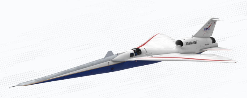
Figure 1. X-59 Design Model [5].
As seen in Figure 1, X-59 has a long nose and delta wings with an uneven surface, having been optimized to reduce the sonic boom to a level inferior to 75PLdB [5]. The use of a high-quality camera for the pilot to view the surrounding environment allows the design of very long noses without the complexity involved in making a moveable nose like in Concorde. This change bears witness to the technological advances in other disciplines that have improved sonic boom mitigation techniques.
However, there exist limitations inherent to the parametric methods as well as in terms of size requirements. The method requires a base set of objects to modify which means that the study functions entirely only on that specific design. This is most evident in Nitin Khasdeo’s wing shape optimization study in which he first defines his wing as a “biconvex delta wing geometry with a chord length of 60ft and maximum thickness ratio of 5% of the chord.” [6] This contrasts with the non-biconvex delta wing used in the X-59, showing the wide applicability of the computational method but also a bias in terms of what is outputted as ‘optimum.’ This is emphasized by the fact that each computational program or method might vary, leading to different results even with the same starting points and by the fact that there are slight differences between simulation and reality. The other limitation is an external size requirement in that the aircraft designed must be capable of maneuvering in the airport, taking into consideration taxiing and parking.
2.2.2. Pulsed forward plasma energy. Pulsed forward plasma energy can be used to mitigate sonic booms by weakening shockwaves or by orienting shockwaves created by the aircraft nose into the horizontal freestream direction. As shown in Figure 2, plasma located in front or underneath the aircraft nose permits sonic boom mitigation effects.
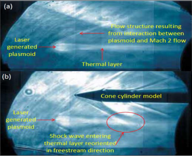
Figure 2. Schlieren Image of shock wave interactions with plasma [7].
However, insufficient research on this topic significantly reduces its prospects as a viable method for sonic boom mitigation. This includes aspects such as the optimal method for generating the plasma; the position of the component allowing that function; if using a laser, choosing the optimal wavelength, intensity and size; its incorporation into an actual aircraft design. As a result, such technology is unlikely to appear on the market in the near future.
2.2.3. Sonic boom circumvention. An alternate solution to the sonic boom problem is using a versatile vehicle that can travel long distances at subsonic and at supersonic speeds efficiently. Boom Overture is the aircraft closest to realizing the objective of commercial supersonic flight and was designed based on this idea. It would travel at supersonic speeds over water and at subsonic speeds over land to avoid disturbing the populace with sonic booms. This strategy requires taking into consideration compromise designs for optimum efficiency at low and high speeds which touch on wing shapes, lift and drag values, engine types… Nevertheless, its value stands out when recognizing the previously mentioned limits to low-boom technology. This is emphasized by the fact that the 75PLdb of the X-59 is obtained with a small research plane, it seems to be a difficult challenge for large commercial civil aircrafts to attain a similar level of loudness using current technology. Consequently, there is considerable weight in Boom Overture’s design as the vanguard to commercial supersonic flight [8].
3. Jet exhaust noise reduction
3.1. Definition and importance
Jet exhaust noise being a major source of airport noise can be reduced mainly through chevron nozzles, but also through variable cycle engines and positioning. It originates from the violent and turbulent mixing of exhaust gases with the atmosphere. The difference in velocity leads to strong shear forces between the two groups which generate noise. The noise intensity is dependent on the mixing rate and exhaust velocity [9]. It matters only during takeoff or landing maneuvers since during cruising, the high altitude causes jet exhaust noise to be unable to affect the ground coupled with the fact that sonic booms overshadow it. Although subsonic aircrafts are affected by it, jet exhaust noise is of greater concern to supersonic aircrafts. The latter requires superior thrust to be able to achieve the same level of lift as a subsonic one due to the standard delta wing shapes in supersonic planes which have a lower lift to drag ratio at low speeds compared to sweptback wings typical of subsonic planes. This generally implies a need for higher exhaust velocities which means greater jet exhaust noises.
3.2. Chevron nozzles
Chevron nozzles are a vastly used method to reduce jet exhaust noise as it allows better mixing of the exhaust gases and the atmosphere. It refers to the arrangement of the nozzle section of an engine with rows of triangular-shaped teeth. Chevron nozzles reduce the noise intensity by encouraging the formation of vortices which leads to a faster dissipation of turbulent kinetic energy, as seen in Figure 3.
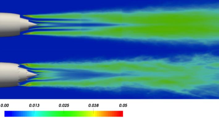
Figure 3. Turbulent kinetic energy distribution for a baseline nozzle (top) and a chevron model (bottom) [10].
This implies smaller scale turbulent structures compared to the ones created by the baseline nozzle. Large scale turbulent structures lead to low frequency noises while small scale turbulent structures to high frequency [10]. This naturally indicates a disadvantage of chevron nozzle implementation which is the creation of high-pitched noises. Though, this should be nuanced by the fact that since high frequency noises do not travel as far as low frequency ones, this method also permits a decrease in noise range in addition to intensity. Another limitation is its negative influence on thrust, with close to 6% thrust loss in certain situations. This is due to greater internal resistances in the engine after adding chevron nozzles, more specifically on the compressor which increases the mechanical force used by the turbine in a standard jet engine [11]. Using optimization methods, modifying the parameters such as chevron spacing, penetration and number, it is possible to reduce the thrust loss to less than a percent [12]. These methods can be empirical, conducted in anechoic chambers; or computational by predicting noise levels and flows [13-14]. As an example, noise level reductions have been able to attain a scale of 6dB using an 8-chevron nozzle with a given penetration [15]. Further optimization in terms of symmetry, penetration and number may lead to better noise reduction. This is in the context of the Federal Aviation Administration (FAA) airport noise regulations which require the loudness to be lower than stage 3, equivalent to a noise level between 89 and 106 dB [16]. As point of reference in the commercial supersonic field, Concorde once had a recorded loudness of 119.4 dB during take-off [17]. The advantage of using chevron nozzles for commercial supersonic planes lies in that even if most research was not conducted specifically for supersonic flight, the results remain applicable to it since take-off and landing occur at subsonic speeds. Therefore, the accumulated chevron nozzle data can be used to design nozzles for commercial supersonic aircraft engines. However, it suffers from similar limitations to the computational fluid dynamics optimization of aircraft shape in that it requires base object design and conditions which implies a similar bias. In contrast, chevron nozzle investigations also include a significant number of experimental studies which means results are more accurate as computational models have more material to be adjusted and verified with.
3.3. Variable cycle engines
Variable cycle engines permit noise reduction in that it boasts high operation efficiency under various environments. It is defined as an engine that can adapt thermodynamic cycles to fit specific flight conditions. It can achieve this through modifying gas flow paths in order to get, in the context of commercial supersonic flight, high engine airflow and low exhaust velocity for efficient flight at low speed, and low airflow and high exhaust velocity for supersonic flight. Therefore, this allows the aircraft to retain turbojet functions required for supersonic flight turbofan characteristics for low speeds. As such, it would not require the extremely noisy afterburners present on the Concorde that were used during take-off to counter its wings’ small lift drag ratio at low speeds, nor would it be limited by turbojets which rely on high exhaust velocities for thrust. Nevertheless, its limitations lie in that it leads to increased weight and complexity which makes it more liable to faults and accidents [18]. In addition, the technology is still in its early days with only a few variable cycle engines, such as the Xa-100 or the YF120. Nonetheless, its advantages outweigh its limitations as the technology matures and variable cycle engine research is essential for improving the commercial supersonic industry.
3.4. Engine positioning
Lastly, the positioning of the engine can decrease the jet exhaust noise perceived by people since placing it above the wing allows the latter to block sound waves partially. As shown in Figure 4, the overall perceived noise level (PNL) is decreased by around 14dB. It should be noted that this includes other sources of noise such as fan inlet and discharge.
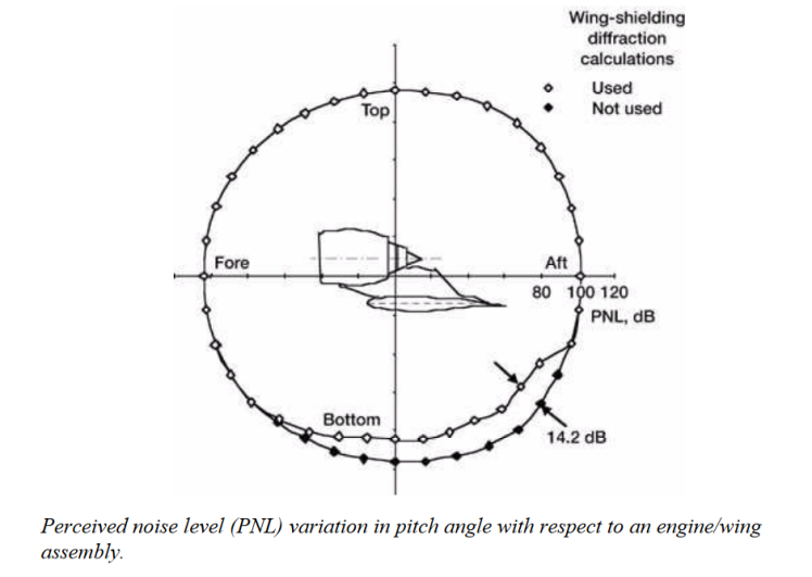
Figure 4. PNL variation in pitch angle with respect to an engine wing [18].
This noise reduction only applies when the wing is of a sufficient size. This concern is only of slight importance as delta wings cover a large area which would permit significant wing shielding. It should be added that this positioning is more efficient at decreasing fan noise rather than jet exhaust noise due to the latter’s existence as a continuous stream extending after the aircraft. Nonetheless, it still permits limited jet exhaust noise reduction ability [19].
4. Conclusion
In the context of aeroacoustics, sonic booms and airport noise are the two main issues to commercial supersonic flight. The first issue can be addressed by optimization of aircraft shape to reduce overpressure rise times, thereby decreasing the perceived loudness of sonic booms. Extensive development in this method reveals limitations in terms of potential computational inaccuracy and bias, and sonic boom mitigation optimization limits due to aircraft size. It can also be addressed through pulsed forward plasma energy permitting the weakening or reorientation of shockwaves. However, the technology is not mature enough for use in current aircrafts. An alternate solution, sonic boom circumvention by traveling at supersonic speeds exclusively over water, encounters challenges in that the aircraft must be extremely efficient at subsonic and supersonic speeds over large distances. On the other hand, airport noise has been narrowed down to one of the key problems, jet exhaust noise. It can be reduced using chevron nozzles which increase exhaust gas and atmosphere mixing rate. Its main limitation lies in the associated thrust reduction caused by its implementation although it can be reduced to some extent through computational optimization and experimental observations. Variable cycle engines target this problem from a more fundamental perspective, by reducing supersonic jet reliance on turbojet engine functions and increasing overall thrust efficiency whilst entailing the design of a heavier and more complex engine. Lastly, placing the engine on top of the wing allows overall aircraft noise, including jet exhaust noise, to be reduced through wing shielding. Noticeable effects rely on large wings and the use of turbofan engines as wing shielding effects are most efficient at reducing fan noise rather than jet exhaust noise. This paper, serving as a summary for recent achievements and future potential methods of research in the aeroacoustics field, is limited by its level of detail for each method and by its scope. Additional considerations with respect to carbon emissions or financial profitability would make a more complete study of commercial supersonic flight feasibility. The application of methods such as wing optimization, and engine positioning in the X-59 reflects the viability of these methods. Further research aimed at the incorporation of pulsed forward plasma energy techniques in aircrafts or at improving variable cycle engines for commercial supersonic flight would make it more feasible.
References
[1]. Banerjee, T. (2019). Design Guidelines for Supersonic Aircrafts in Civil Aviation. International Journal of Aviation, Aeronautics, and Aerospace. https://doi.org/10.15394/ijaaa.2019.1430
[2]. Li, W., & Geiselhart, K. (2021). Multidisciplinary Design Optimization of Low-Boom Supersonic Aircraft with Mission Constraints. AIAA Journal, 59(1), 165–179. https://doi.org/ 10.2514/1.j059237
[3]. Ph, & Student. (2018). School of Aerospace Transport and Manufacturing, AIAA Student Member. 2 Professor, School of Aerospace Transport and Manufacturing. 2018–3278. https://doi.org/10.2514/6.2018-3278
[4]. Lavelle, T., & Curlett, B. (1994). Graphical User Interface for the NASA FLOPS Aircraft Performance and Sizing Code • National Aeronautics and Space Administration. In NASA Technical Memorandum (p. 106649). https://ntrs.nasa.gov/api/citations/19950008190/ downloads/19950008190.pdf
[5]. Quieting the Sonic Boom X-59 Quiet Supersonic Technology X-Plane. (n.d.). https://www.lockheedmartin.com/content/dam/lockheed-martin/aero/documents/quietSuperS onic/P22-01661%20Product%20Card%20X-59.pdf
[6]. Khasdeo, N. (2007). Sonic Boom Focusing Prediction and Delta Wing Shape Sonic Boom Focusing Prediction and Delta Wing Shape Optimization for Boom Mitigation Studies Optimization for Boom Mitigation Studies. https://doi.org/10.25777/hx9q-ja15
[7]. Blankson, I. (2016). Aerospace Applications of Non- Equilibrium Plasma AIAA AVIATION 2016: INVITED SESSION SESSION 264-FD-60: IDENTIFYING THE IMPACT OF NON- EQUILIBRIUM MECHANISMS IN ENGINEERING FLOWS. https://ntrs.nasa.gov/ api/citations/20170002538/downloads/20170002538.pdf
[8]. Boom Supersonic. (2019). Boom - Overture. Boomsupersonic.com. https://boomsupersonic. com/overture
[9]. Noise Control/Supression. (2020). Purdue.edu. https://engineering.purdue.edu/~propulsi/ propulsion/jets/basics/noise.html
[10]. Reducing Jet Noise with Chevron Nozzles. (2017, April 26). Gauss Centre for Supercomputing E.V. https://www.gauss-centre.eu/results/computational-and-scientific-engineering/reducing-jet-noise-with-chevron-nozzles
[11]. Cican, G., Deaconu, M., & Crunteanu, D.-E. (2021). Impact of Using Chevrons Nozzle on the Acoustics and Performances of a Micro Turbojet Engine. Applied Sciences, 11(11), 5158. https://doi.org/10.3390/app11115158
[12]. Wernet, J., & Bridges. (2021). Mark P Characterization of Chevron Nozzle Performance. https://ntrs.nasa.gov/api/citations/20210020164/downloads/TM-20210020164.pdf
[13]. Ansgar Niemöller, Meinke, M., Schroeder, W., Albring, T., & Gauger, N. R. (2019). Noise Reduction Using a Direct-Hybrid CFD/CAA Method. https://doi.org/10.2514/6.2019-2579
[14]. Heeb, N., Gutmark, E., & Kailasanath, K. (2016). Impact of chevron spacing and asymmetric distribution on supersonic jet acoustics and flow. Journal of Sound and Vibration, 370, 54–81. https://doi.org/10.1016/j.jsv.2016.01.047
[15]. Callender, B., Gutmark, E., & Martens, S. (2005). Far-Field Acoustic Investigation into Chevron Nozzle Mechanisms and Trends. AIAA Journal, 43(1), 87–95. https://doi.org/10.2514/1.6150
[16]. Federal Airport Noise Regulations and Programs. (2021). https://sgp.fas.org/crs/misc/R46920.pdf
[17]. Concorde: technical feat, financial fiasco. (n.d.). Phys.org. https://phys.org/news/2019-03-concorde-technical-feat-financial-fiasco.html
[18]. Denney, R. K., Tai, J. C., Kestner, B. K., & Mavris, D. N. (2005). Variable Cycle Optimization for Supersonic Commercial Applications. SAE Transactions, 114, 1354–1361. https://www.jstor.org/stable/44682832
[19]. Noise-Reduction Benefits Analyzed for Over-the-Wing-Mounted Advanced Turbofan Engines. (n.d.). Retrieved August 6, 2023, from https://ntrs.nasa.gov/api/citations/20050192097/ downloads/20050192097.pdf
Cite this article
LIU,C.P.Q. (2023). Evaluation of feasibility of commercial supersonic flight based on aeroacoustics. Theoretical and Natural Science,13,11-17.
Data availability
The datasets used and/or analyzed during the current study will be available from the authors upon reasonable request.
Disclaimer/Publisher's Note
The statements, opinions and data contained in all publications are solely those of the individual author(s) and contributor(s) and not of EWA Publishing and/or the editor(s). EWA Publishing and/or the editor(s) disclaim responsibility for any injury to people or property resulting from any ideas, methods, instructions or products referred to in the content.
About volume
Volume title: Proceedings of the 3rd International Conference on Computing Innovation and Applied Physics
© 2024 by the author(s). Licensee EWA Publishing, Oxford, UK. This article is an open access article distributed under the terms and
conditions of the Creative Commons Attribution (CC BY) license. Authors who
publish this series agree to the following terms:
1. Authors retain copyright and grant the series right of first publication with the work simultaneously licensed under a Creative Commons
Attribution License that allows others to share the work with an acknowledgment of the work's authorship and initial publication in this
series.
2. Authors are able to enter into separate, additional contractual arrangements for the non-exclusive distribution of the series's published
version of the work (e.g., post it to an institutional repository or publish it in a book), with an acknowledgment of its initial
publication in this series.
3. Authors are permitted and encouraged to post their work online (e.g., in institutional repositories or on their website) prior to and
during the submission process, as it can lead to productive exchanges, as well as earlier and greater citation of published work (See
Open access policy for details).
References
[1]. Banerjee, T. (2019). Design Guidelines for Supersonic Aircrafts in Civil Aviation. International Journal of Aviation, Aeronautics, and Aerospace. https://doi.org/10.15394/ijaaa.2019.1430
[2]. Li, W., & Geiselhart, K. (2021). Multidisciplinary Design Optimization of Low-Boom Supersonic Aircraft with Mission Constraints. AIAA Journal, 59(1), 165–179. https://doi.org/ 10.2514/1.j059237
[3]. Ph, & Student. (2018). School of Aerospace Transport and Manufacturing, AIAA Student Member. 2 Professor, School of Aerospace Transport and Manufacturing. 2018–3278. https://doi.org/10.2514/6.2018-3278
[4]. Lavelle, T., & Curlett, B. (1994). Graphical User Interface for the NASA FLOPS Aircraft Performance and Sizing Code • National Aeronautics and Space Administration. In NASA Technical Memorandum (p. 106649). https://ntrs.nasa.gov/api/citations/19950008190/ downloads/19950008190.pdf
[5]. Quieting the Sonic Boom X-59 Quiet Supersonic Technology X-Plane. (n.d.). https://www.lockheedmartin.com/content/dam/lockheed-martin/aero/documents/quietSuperS onic/P22-01661%20Product%20Card%20X-59.pdf
[6]. Khasdeo, N. (2007). Sonic Boom Focusing Prediction and Delta Wing Shape Sonic Boom Focusing Prediction and Delta Wing Shape Optimization for Boom Mitigation Studies Optimization for Boom Mitigation Studies. https://doi.org/10.25777/hx9q-ja15
[7]. Blankson, I. (2016). Aerospace Applications of Non- Equilibrium Plasma AIAA AVIATION 2016: INVITED SESSION SESSION 264-FD-60: IDENTIFYING THE IMPACT OF NON- EQUILIBRIUM MECHANISMS IN ENGINEERING FLOWS. https://ntrs.nasa.gov/ api/citations/20170002538/downloads/20170002538.pdf
[8]. Boom Supersonic. (2019). Boom - Overture. Boomsupersonic.com. https://boomsupersonic. com/overture
[9]. Noise Control/Supression. (2020). Purdue.edu. https://engineering.purdue.edu/~propulsi/ propulsion/jets/basics/noise.html
[10]. Reducing Jet Noise with Chevron Nozzles. (2017, April 26). Gauss Centre for Supercomputing E.V. https://www.gauss-centre.eu/results/computational-and-scientific-engineering/reducing-jet-noise-with-chevron-nozzles
[11]. Cican, G., Deaconu, M., & Crunteanu, D.-E. (2021). Impact of Using Chevrons Nozzle on the Acoustics and Performances of a Micro Turbojet Engine. Applied Sciences, 11(11), 5158. https://doi.org/10.3390/app11115158
[12]. Wernet, J., & Bridges. (2021). Mark P Characterization of Chevron Nozzle Performance. https://ntrs.nasa.gov/api/citations/20210020164/downloads/TM-20210020164.pdf
[13]. Ansgar Niemöller, Meinke, M., Schroeder, W., Albring, T., & Gauger, N. R. (2019). Noise Reduction Using a Direct-Hybrid CFD/CAA Method. https://doi.org/10.2514/6.2019-2579
[14]. Heeb, N., Gutmark, E., & Kailasanath, K. (2016). Impact of chevron spacing and asymmetric distribution on supersonic jet acoustics and flow. Journal of Sound and Vibration, 370, 54–81. https://doi.org/10.1016/j.jsv.2016.01.047
[15]. Callender, B., Gutmark, E., & Martens, S. (2005). Far-Field Acoustic Investigation into Chevron Nozzle Mechanisms and Trends. AIAA Journal, 43(1), 87–95. https://doi.org/10.2514/1.6150
[16]. Federal Airport Noise Regulations and Programs. (2021). https://sgp.fas.org/crs/misc/R46920.pdf
[17]. Concorde: technical feat, financial fiasco. (n.d.). Phys.org. https://phys.org/news/2019-03-concorde-technical-feat-financial-fiasco.html
[18]. Denney, R. K., Tai, J. C., Kestner, B. K., & Mavris, D. N. (2005). Variable Cycle Optimization for Supersonic Commercial Applications. SAE Transactions, 114, 1354–1361. https://www.jstor.org/stable/44682832
[19]. Noise-Reduction Benefits Analyzed for Over-the-Wing-Mounted Advanced Turbofan Engines. (n.d.). Retrieved August 6, 2023, from https://ntrs.nasa.gov/api/citations/20050192097/ downloads/20050192097.pdf