


1. Introduction
The concept of the Arithmetic Logic Unit was initially introduced by John von Neumann in 1945 during his work on the foundational aspects of the EDVAC computer. As the 1970s ushered in the era of microprocessors, the evolution of the ALU entered an advanced phase. Adhering to Moore’s Law, the size of transistors has continually decreased, facilitating the integration of more expansive ALUs into microprocessors [1].
An ALU, an essential component within numerous processors, typically consists of two primary units: logical operations and arithmetic operations. This design allows the ALU to execute a wide array of mathematical and logical functions [2]. Communication with the ALU is facilitated through buses. An incoming instruction comprises an instruction word, occasionally referred to as a machine instruction word. This word encompasses an operation code (opcode), one or several operands, and occasionally a format code. The opcode delineates the operation the ALU should execute and the number of operands involved in that particular operation.
Verilog Hardware Description Language is currently the predominant language used for hardware description in Field Programmable Gate Arrays (FPGA) and digital Integrated Circuit (IC) design. It ranks among the top three major hardware description languages. Verilog Hardware Description Language offers a textual representation of the structure and behavior of a digital system. Through Verilog, one can articulate logical circuit diagrams, logical expressions, and the logical functions executed by a digital logic system [3]. Modules synthesized using this language can be implemented as hardware circuits, appearing in the final layout on FPGA, Complex Programmable Logic Device (CPLD), Application-Specific Integrated Circuit (ASIC), and more. The simulation stimulus file typically verifies the accuracy of the synthesized design module.
Quartus the Second is a holistic Complex Programmable Logic Device (CPLD)/Field Programmable Gate Array (FPGA) development tool [4]. It is compatible with various design inputs, including schematic diagrams, Very High-Speed Integrated Circuit Hardware Description Language (VHDL), Verilog Hardware Description Language, and Advanced Hardware Description Language. Embedded within Quartus the Second are its native synthesizer and simulator, which together can navigate the entire Programmable Logic Device (PLD) design trajectory, from the design’s inception to its hardware configuration.
Modelsim, a representative simulation tool, endorses Verilog, Very High-Speed Integrated Circuit Hardware Description Language (VHDL), and their combined simulation processes. During the simulation, Modelsim produces a waveform diagram grounded in the design and simulation documents. By scrutinizing this waveform, one can ascertain the functionality and accuracy of the designed code.
2. Relevant Theories
2.1. ALU Implementation
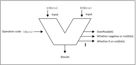
Figure 1. ALU schematic diagram (Photo/Picture credit: Original).
Figure 1 is the schematic ALU symbol. In the eight-bit ALU, the input has two 8-bit operands, A and B, and a 4-bit operator code. Operation code is used to tell the ALU what actions to do, such as addition, subtraction, etc. The ALU processes the input through the arithmetic units and the logical units, and outputs the results.
2.2. Module Analysis
Table 1. Operation code and operation instructions.
Operation CODE | Operation instruction |
0000 | Addition |
0001 | Subtraction |
0010 | Multiplication |
0011 | Division |
0100 | Shift left |
0101 | Shift right |
0110 | Rotate left |
0111 | Rotate right |
1000 | AND |
1001 | OR |
1010 | XOR |
1011 | NOR |
1100 | NAND |
1101 | XNOR |
1110 | Comparator |
1111 | Comparator |
Table 1 is the operation code of the ALU and the operation instructions corresponding thereto respectively, the 4-bit operation code were used to define the operation type [5]. Code from 0000 to 0011 are arithmetic calculation, code 0000 corresponds to addition for the addition calculation of the ALU, code 0001 to subtraction for the ALU subtraction calculation, code 0010 for the multiplication for the ALU multiplication, and code 0011 to division for the division calculation of the ALU.
From code 0100 to code 1101 are logical calculation, code 0100 and code 0101 are shifting, code 0110 and code 0111 are rotating, from code 1000 to code 1101 are logic gate operation [6]. Code 1110 and code 1111 are two comparators., code 1110 is comparison of value, and code 1111 is comparison of equality.
3. Alu Design and Simulation Workflow
3.1. System Design
Define input and output: 8-bit input A and B, 4-bit input ALU _ Sel, 8-bit output ALU _ Out and 1-bit output CarryOut.
Define the intermediate variable ALU _ Result to store the results of the ALU operation.
Define a temporary variable tmp, used to store the value of A plus B.
Assign the ALU _ Out output to the ALU _ Result.
The tmp was assigned as {1 ‘b0, A} + {1’ b0, B}.
Assign the CarryOut output to the 8th bit of tmp.
Use the case statement in the always @ (*) block to perform different operations based on the value of the ALU _ Sel.
For each case, the ALU _ Result is assigned to the corresponding operation result.
If the value of ALU _ Sel cannot match any case, the arithmetic addition is performed by default [7].
In this project, we complete this project through Quartus II and Modelsim co-simulation. Firstly, we use Quartus II to create a new project and a new file in turn, select Verilog HDL, write code and save (file name and module name should be thesame), then create a new file and write TestBench code and save as alu_tb.v. After the code is written, configure the Modelsim path → Tools → Options → EDA Tool Options, and configure Modelsim-Altera, then associate the TestBench file. Click Assignment →Setting → simulation, configure Verilog HDL, and input the TestBench name. In Top level module of TestBench, enter the name of the highest level module in TestBench. Select the file alu_ tb. v and add, then apply to complete the TestBench file association. After that, compile and run the code, then display the waveforms.
Finally, Select zoom full to display all waveforms [8].
3.2. Code Implementation
The code is written as follows. Firstly, define the input and output: 8-bit input A and B, 4-bit input ALU_ Sel, 8-bit output ALU_ Out, and 1-bit output CarryOut. The intermediate variable ALU_ Result is then defined to store the result of the ALU operation. Then define A temporary variable, tmp, to store the values of a plus B. The ALU_ Out output is then assigned the value ALU_ Result. Then assign tmp to {1’b0, A} + {1’b0, B}. The CarryOut output is then assigned to the 8th bit of tmp. Then use the case statement in the always @ (*) block to perform different operations depending on the value of ALU_ Sel. For each case, ALU_ Result is assigned to the corresponding result of the operation. If the value of ALU_ Sel does not match anything, arithmetic addition is performed by default.
3.3. Simulation circuit diagram implementation
The Quartus II software supports simulation circuit diagram, so the implementation of simulation circuit will be based on Quartus II [9], and Figure 2 is the circuit diagram obtained in Quartus II simulation.
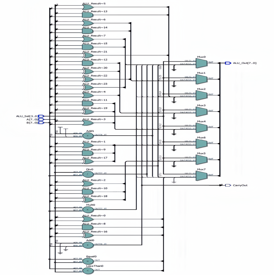
Figure 2. Simulation circuit (Photo/Picture credit: Original).
3.4. Simulation waveform
Since Quartus II and ModelSim can be combined simulation, this paper adopts the combined simulation. ModelSim Used for the simulation of the waveforms.
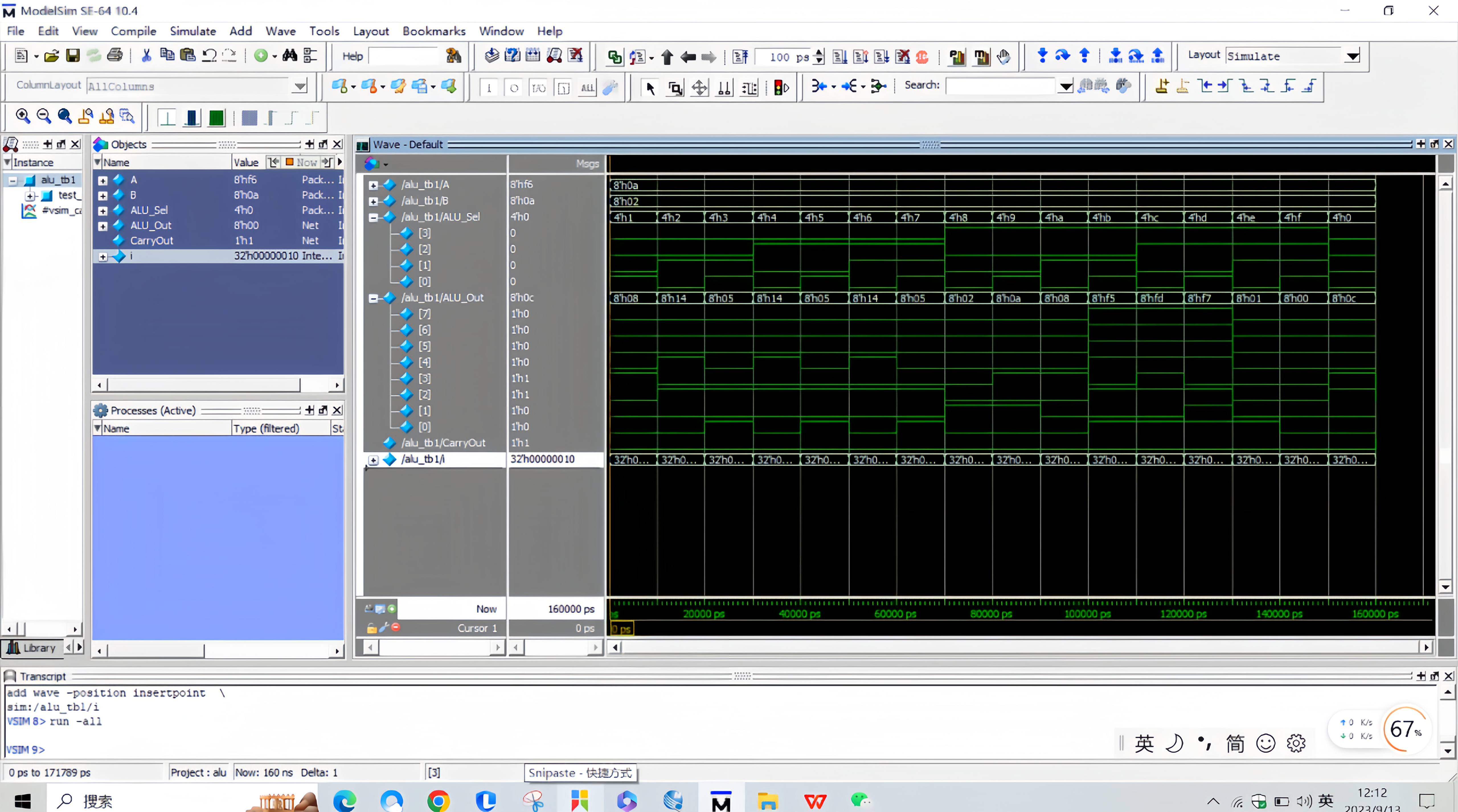
Figure 3. Simulation waveform (Photo/Picture credit: Original).
Figure3 is the Simulation waveform diagram of ALU from modelsim software.
4. Challenge
4.1. Difficulties in the process of achieving 8-bit ALU
1) Difficulties were encountered in implementing XOR, NOR, NAND and XNOR fuction, and were finally solved by consulting data.
2) When writing code files, there are many erors, the most is syntax errors. Through repeated modification and compilation, they can be successfully compiled.
3) After completing the 8-bit ALU, a new problem is how to change the 8-bit ALU to 64-bit ALU. After thinking and in-depth learning, the following methods are summarized
Changing an 8-bit ALU to a 64-bit ALU requires the following steps [10]:
Expand bit width: Expand each bit width in the ALU to 64 bits. This by copying and filling “0”, ensuring that each operand and result has 64 bits.
Expansion control signal: Due to the change of bit width, the control signal of ALU also needs to be expanded accordingly. Ensure that each control signal matches the new bit width of the 64-bit ALU.
Modify the operation logic: according to the ALU operation logic of 64-bit operand and control signal, modify to accommodate the new bit width. Make sure that each operation correctly calculates the 64-bit data and generates the correct result.
Update status flag bit: If there are status flag bits in the original 8-bit ALU (such as carry flag, zero mark, etc.), the flag bit needs to be updated accordingly to accommodate the results of the 64-bit operand.
5. Conclusion
In the scope of this study, an 8-bit Arithmetic Logic Unit (ALU) has been meticulously crafted, encompassing a multitude of operations such as addition, subtraction, multiplication, division, logical left shift, logical right shift, rotate left, rotate right, OR, XOR, NOR, NAND, XNOR, value comparison, and equality check. The precision and robustness of this 8-bit ALU were confirmed by analyzing the resultant waveforms. Engaging in the design of the 8-bit ALU enriched the comprehension of digital logic circuit design methodologies and fostered a more profound grasp of intricate circuitry constructs. The ALU’s design proceeded in a structured manner: beginning with a foundation based on the ALU’s principles and functionalities; followed by the establishment of the digital circuit module tailored to operation instructions; and culminating in an integrated simulation utilizing both Quartus the Second and ModelSim. Venturing into this design deepened the understanding of digital logic design and honed the skills related to logical circuit creation. Such an endeavor has undoubtedly fortified the foundation for more advanced research and explorations in the field.
References
[1]. G. Surekha, G. Madesh, M. P. Kumar and H. Sriramoju, “Design and Implementation of Arithmetic and Logic Unit (ALU),” 2023 2nd International Conference on Applied Artificial Intelligence and Computing (ICAAIC), Salem, India, 2023, pp. 1530-1536, doi: 10.1109/ ICAAIC56838.2023.10140574.
[2]. Sakshi Samaiya and Anupreksha jain, “A review article of FPGA ALU unit design based on GA”, International journal of scientific reasearch and engineering trends, Volume 4, Issue 4, July-Aug 2018, ISS (online).
[3]. Nilam Gadda, Dr U. Eranna,”64-bit ALU design using vedic mathematics”,2020 ic-ETITE.
[4]. Suma T. Hedge, Dr. siva Yellampalli and Nandeesh R, “Design and implemtation of ALU using redundant binary signed digit”<, International Conference on VLSI, communication and Instrumenation (ICVCI) 2011, Proceedings published by International Journal of Computer Applications (IJCA), pp: 30-35.
[5]. Riki, S., Serajeh Hassani, F. Designing a one-bit coplanar QCA ALU using a novel robust area-efficient three-input majority gate design. J Supercomput 79, 17897-17918(2023). https://doi-org-s.elink.xjtlu.edu.cn:443/10.1007/s11227-023-05280-6.
[6]. Zhu, X., Zhao, Z., Wei, X., & others. (2021). Action recognition method based on wavelet transform and neural network in wireless network. In 2021 5th International Conference on Digital Signal Processing (pp. 60-65).
[7]. Patidar, M., Singh, U., Shukla, S.K. et al. An ultra-area-efficient ALU design in QCA technology using synchronized clock zone scheme. J Supercomput 79, 8265–8294 (2023). https://doi-org-s.elink.xjtlu.edu.cn:443/10.1007/s11227-022-05012-2.
[8]. Zhu Yijie, Zhang Xi, Yu Jun. Optimized design of the arithmetic logic unit [J]. Microelectronics and computers, 2004,21(9):155-157. DOI:10.3969/j. issn.1000-7180.2004.09.043.
[9]. Hameed, A. L., Hameed, M., & Hasan, R. A. (2022). A New Technology for Reducing Dynamic Power Consumption in 8-Bit ALU Design. Iraqi Journal of Industrial Research, 9(3), 12-22.
[10]. Shirol, S. B., Ramakrishna, S., & Shettar, R. B. (2020). A Novel Design and Implementation of 8-Bit and 16-Bit Hybrid ALU. In Intelligent Systems Design and Applications: 18th International Conference on Intelligent Systems Design and Applications (ISDA 2018) held in Vellore, India, December 6-8, 2018, Volume 1 (pp. 32-42). Springer International Publishing.
Cite this article
Huang,Z. (2023). Design and implementation of an 8-bit ALU based on verilog HDL. Theoretical and Natural Science,14,180-185.
Data availability
The datasets used and/or analyzed during the current study will be available from the authors upon reasonable request.
Disclaimer/Publisher's Note
The statements, opinions and data contained in all publications are solely those of the individual author(s) and contributor(s) and not of EWA Publishing and/or the editor(s). EWA Publishing and/or the editor(s) disclaim responsibility for any injury to people or property resulting from any ideas, methods, instructions or products referred to in the content.
About volume
Volume title: Proceedings of the 3rd International Conference on Computing Innovation and Applied Physics
© 2024 by the author(s). Licensee EWA Publishing, Oxford, UK. This article is an open access article distributed under the terms and
conditions of the Creative Commons Attribution (CC BY) license. Authors who
publish this series agree to the following terms:
1. Authors retain copyright and grant the series right of first publication with the work simultaneously licensed under a Creative Commons
Attribution License that allows others to share the work with an acknowledgment of the work's authorship and initial publication in this
series.
2. Authors are able to enter into separate, additional contractual arrangements for the non-exclusive distribution of the series's published
version of the work (e.g., post it to an institutional repository or publish it in a book), with an acknowledgment of its initial
publication in this series.
3. Authors are permitted and encouraged to post their work online (e.g., in institutional repositories or on their website) prior to and
during the submission process, as it can lead to productive exchanges, as well as earlier and greater citation of published work (See
Open access policy for details).
References
[1]. G. Surekha, G. Madesh, M. P. Kumar and H. Sriramoju, “Design and Implementation of Arithmetic and Logic Unit (ALU),” 2023 2nd International Conference on Applied Artificial Intelligence and Computing (ICAAIC), Salem, India, 2023, pp. 1530-1536, doi: 10.1109/ ICAAIC56838.2023.10140574.
[2]. Sakshi Samaiya and Anupreksha jain, “A review article of FPGA ALU unit design based on GA”, International journal of scientific reasearch and engineering trends, Volume 4, Issue 4, July-Aug 2018, ISS (online).
[3]. Nilam Gadda, Dr U. Eranna,”64-bit ALU design using vedic mathematics”,2020 ic-ETITE.
[4]. Suma T. Hedge, Dr. siva Yellampalli and Nandeesh R, “Design and implemtation of ALU using redundant binary signed digit”<, International Conference on VLSI, communication and Instrumenation (ICVCI) 2011, Proceedings published by International Journal of Computer Applications (IJCA), pp: 30-35.
[5]. Riki, S., Serajeh Hassani, F. Designing a one-bit coplanar QCA ALU using a novel robust area-efficient three-input majority gate design. J Supercomput 79, 17897-17918(2023). https://doi-org-s.elink.xjtlu.edu.cn:443/10.1007/s11227-023-05280-6.
[6]. Zhu, X., Zhao, Z., Wei, X., & others. (2021). Action recognition method based on wavelet transform and neural network in wireless network. In 2021 5th International Conference on Digital Signal Processing (pp. 60-65).
[7]. Patidar, M., Singh, U., Shukla, S.K. et al. An ultra-area-efficient ALU design in QCA technology using synchronized clock zone scheme. J Supercomput 79, 8265–8294 (2023). https://doi-org-s.elink.xjtlu.edu.cn:443/10.1007/s11227-022-05012-2.
[8]. Zhu Yijie, Zhang Xi, Yu Jun. Optimized design of the arithmetic logic unit [J]. Microelectronics and computers, 2004,21(9):155-157. DOI:10.3969/j. issn.1000-7180.2004.09.043.
[9]. Hameed, A. L., Hameed, M., & Hasan, R. A. (2022). A New Technology for Reducing Dynamic Power Consumption in 8-Bit ALU Design. Iraqi Journal of Industrial Research, 9(3), 12-22.
[10]. Shirol, S. B., Ramakrishna, S., & Shettar, R. B. (2020). A Novel Design and Implementation of 8-Bit and 16-Bit Hybrid ALU. In Intelligent Systems Design and Applications: 18th International Conference on Intelligent Systems Design and Applications (ISDA 2018) held in Vellore, India, December 6-8, 2018, Volume 1 (pp. 32-42). Springer International Publishing.