


1. Introduction
The reflection of light, while universally present in daily life, tends to go unnoticed most of the time. Based on various factors, there is a certain ratio between the amount of light that is reflected and refracted. The author of this paper researched many of those factors, including temperature, the material of the medium, and the angle of incidence of light, and even considered investigating the final intensity of light after multiple reflections and refractions within a light-permeable medium. However, many of those factors and related approaches are too complex for an appropriate experimental design. Eventually, after careful examination, the author decided to focus on the relationship between the angle of incidence and the intensity of the light reflected, leading to the research question of how the angle of light incidence on a glass block affects the illuminance (lx) of the reflected light. An experiment was conducted with analysis and evaluation of the raw data collected to investigate this research question, and it was conducted by measuring the intensity of the reflected green laser light beam of wavelength 532nm from a glass block using a light illuminance sensor at different angles of the initial angle of light incidence.
Research on reflectance can help design technology for light analysis. For example, spectrometry is based on the analysis of light intensities and wavelengths, which is closely related to the reflectance and transmittance of light over different media. It can also be valuable in the fields related to lighting and displays. Since light transmissions always need different media, this study is also helpful to many applications related to the angle of lighting and the resulting intensity of light.
2. Theories and hypothesis
Light is a transverse wave with electromagnetic field vectors perpendicular to the propagation of the wave. The energy transfer of light can be presented in different ways. Irradiance (also known as intensity) and illuminance are the two most common measurements of the power of light per area of light perception. The unit of intensity \( I \) is watts per square meter \( ({Wm^{-2}}) \) , and the unit of illuminance \( {E_{v}} \) is lux (lx). The illuminance of light is another way to express the intensity of light, and they are directly proportional to each other and to the power of light transmitted \( P \) [1]:
\( {E_{v}}∝I∝P\ \ \ (1) \)
The polarization of waves is a characteristic of transverse waves, whose direction of fluctuation is perpendicular to the direction of energy transfer. Light, which is also a type of transverse wave, has different types of polarizations: linear, circular, and elliptical polarizations [2]. The linear polarization is also called plane polarization.
| |
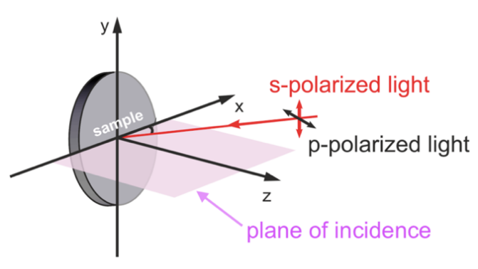
Figure 1. Direction of s-polarized light and p-polarized light relative to the plane of incidence [3]. | Figure 2. Angles of incidence, reflection, transmission, and refractive indices (Illustrated by the author of the paper). |
A light is said to be linearly polarized when the direction of the oscillation of its electric field vector becomes regular. In this investigation, only the case of linear polarization will be considered because it can be used to simply explain the reflection of light over a plane of interface and help to approach the intensity of reflected light.
In linearly polarized light, there are s-polarized and p-polarized light. In the context of reflections and transmissions of light between two different media, s-polarized light can be referred to as when the direction of the electric field vector of the light is perpendicular to the plane of incidence, where p-polarized light’s electric field vector is parallel to the plane of incidence as shown in Figure 1 [4].
In this experiment, let \( {θ_{i}} \) be the angle of incidence where \( 0≤{θ_{i}}≤\frac{π}{2} \) , \( {θ_{r}} \) be the angle of reflection, and \( {θ_{t}} \) be the angle of transmission as seen in Figure 2.
According to the Law of Reflection [5],
\( {θ_{i}}={θ_{r}}\ \ \ (2) \)
The relationship between the \( {θ_{i}} \) and \( {θ_{t}} \) can be described by the Snell’s Law based on the refractive indices of the two media:
\( {n_{i}}sin{{θ_{i}}}={n_{t}}sin{{θ_{t}}}\ \ \ (3) \)
Here, \( {n_{i}} \) is the refractive index of the medium where the light is coming from, and \( {n_{t}} \) is the refractive index of the medium where the light is transmitting to, as in Figure 2 [2]. In this particular investigation where the transmission of light will take place between media of air and a glass block, the refractive indices of air and the glass block need not to be individually known, because only the ratio of \( {n_{i}} \) to \( {n_{t}} \) will be used to express \( {θ_{t}} \) with Equation \( (3) \) in terms of \( {θ_{i}} \) , which will be seen later. Fresnel’s coefficients for reflection describe the ratio of field components of reflected and transmitted light over incident light. The Fresnel’s coefficients for the reflectance of the s-polarized light \( {r_{s}} \) and p-polarized light \( {r_{p}} \) are as below [6]:
\( {r_{s}}=\frac{sin{({θ_{t}}-{θ_{i}})}}{sin{({θ_{t}}+{θ_{i}})}}\ \ \ (4) \)
\( {r_{p}}=\frac{tan{({θ_{t}}-{θ_{i}})}}{tan{({θ_{t}}+{θ_{i}})}}\ \ \ (5) \)
Before applying Fresnel’s coefficients, it should be noted that there are five essential preconditions of the application of Fresnel’s coefficients that may have implications in experimental contexts: The incident light is a plane wave; there is an interface between the two optical media; the interface is a completely flat surface; the two media have different but consistent refractive indices; the media are homogeneous and isotropic [7].
The reflectance \( R \) is the ratio of intensity of reflected light \( {I_{r}} \) to the incident light \( {I_{i}} \) :
\( R=\frac{{I_{r}}}{{I_{i}}}\ \ \ (6) \)
The reflectance of s-polarzied light \( {R_{s}} \) and p-polarized light \( {R_{p}} \) is given by the square of the corresponding Fresnel’s coefficients [2]:
\( {R_{s}}=r_{s}^{2}=\frac{{sin^{2}}{({θ_{t}}-{θ_{i}})}}{{sin^{2}}{({θ_{t}}+{θ_{i}})}}\ \ \ (7) \)
\( {R_{p}}=r_{p}^{2}=\frac{{tan^{2}}{({θ_{t}}-{θ_{i}})}}{{tan^{2}}{({θ_{t}}+{θ_{i}})}}\ \ \ (8) \)
The total intensity of reflected light can be expressed by the sum of the intensity of s-polarized reflected light \( I_{r}^{(s)} \) and p-polarized reflected light \( I_{r}^{(p)} \) :
\( {I_{r}}=I_{r}^{(s)}+I_{r}^{(p)}\ \ \ (9) \)
Combining Equations \( (6) \) and \( (9) \) :
\( {I_{r}}={R_{s}}I_{i}^{(s)}+{R_{p}}I_{i}^{(p)}\ \ \ (10) \)
Replacing the \( {R_{s}} \) and \( {R_{p}} \) in Equation \( (10) \) with Euations \( (7) \) and \( (8) \) :
\( {I_{r}}=I_{i}^{(s)}\frac{{sin^{2}}{({θ_{t}}-{θ_{i}})}}{{sin^{2}}{({θ_{t}}+{θ_{i}})}}+I_{i}^{(p)}\frac{{tan^{2}}{({θ_{t}}-{θ_{i}})}}{{tan^{2}}{({θ_{t}}+{θ_{i}})}}\ \ \ (11) \)
Equation \( (3) \) can be written in the form that extracts \( {θ_{t}} \) :
\( {θ_{t}}=arcsin{(\frac{{n_{i}}sin{{θ_{i}}}}{{n_{t}}})}\ \ \ (12) \)
Substituting \( {θ_{t}} \) from Equation \( (11) \) using Equation \( (12) \) :
\( {I_{r}}=I_{i}^{(s)}(\frac{{sin^{2}}{(arcsin{(\frac{{n_{i}}sin{{θ_{i}}}}{{n_{t}}})}-{θ_{i}})}}{{sin^{2}}{(arcsin{(\frac{{n_{i}}sin{{θ_{i}}}}{{n_{t}}})}+{θ_{i}})}})+I_{i}^{(p)}(\frac{{tan^{2}}{(arcsin{(\frac{{n_{i}}sin{{θ_{i}}}}{{n_{t}}})}-{θ_{i}})}}{{tan^{2}}{(arcsin{(\frac{{n_{i}}sin{{θ_{i}}}}{{n_{t}}})}+{θ_{i}})}})\ \ \ (13) \)
While the refractive indices of the media \( {n_{i}} \) and \( {n_{t}} \) and the intensities of s-polarized reflected light \( I_{r}^{(s)} \) and p-polarized reflected light \( I_{r}^{(p)} \) are controlled, Equation \( (13) \) expresses the intensity of reflected light \( {I_{r}} \) in terms of the angle of incidence \( {θ_{i}} \) . Since Equation \( (1) \) tells that intensity is directly proportional to illuminance, Equation \( (13) \) can be written as
\( {{E_{v}}_{r}}({θ_{i}})={E_{v}}_{i}^{(s)}(\frac{{sin^{2}}{(arcsin{(\frac{{n_{i}}sin{{θ_{i}}}}{{n_{t}}})}-{θ_{i}})}}{{sin^{2}}{(arcsin{(\frac{{n_{i}}sin{{θ_{i}}}}{{n_{t}}})}+{θ_{i}})}})+{E_{v}}_{i}^{(p)}(\frac{{tan^{2}}{(arcsin{(\frac{{n_{i}}sin{{θ_{i}}}}{{n_{t}}})}-{θ_{i}})}}{{tan^{2}}{(arcsin{(\frac{{n_{i}}sin{{θ_{i}}}}{{n_{t}}})}+{θ_{i}})}})\ \ \ (14) \)
The values of \( {E_{v}}_{i}^{(s)} \) and \( {E_{v}}_{i}^{(p)} \) are as well controlled variables that are experimentally determined, with \( {E_{v}}_{i}^{(s)}= \) 30677.7 ± 238.8 and \( {E_{v}}_{i}^{(p)}= \) 7324.9 ± 63.2. It is also experimentally determined that \( \frac{{n_{i}}}{{n_{t}}}= \) 0.6044 ± 0.0021. These values can be substituted into Equation \( (14) \) to get:
\( {{E_{v}}_{r}}({θ_{i}})=30677.7(\frac{{sin^{2}}{(arcsin{((0.6044)sin{{θ_{i}}})}-{θ_{i}})}}{{sin^{2}}{(arcsin{((0.6044)sin{{θ_{i}}})}+{θ_{i}})}})+7324.9(\frac{{tan^{2}}{(arcsin{((0.6044)sin{{θ_{i}}})}-{θ_{i}})}}{{tan^{2}}{(arcsin{((0.6044)sin{{θ_{i}}})}+{θ_{i}})}})\ \ \ (15) \)
Moreover, to hypothesize, a sketch of graph of \( {{E_{v}}_{r}}({θ_{i}}) \) in Equation \( (15) \) shows that \( \frac{d{E_{{v_{r}}}}}{d{θ_{i}}} \gt 0 \) and \( \frac{{d^{2}}{E_{{v_{r}}}}}{dθ_{i}^{2}} \gt 0 \) for \( 0 \lt {θ_{i}} \lt \frac{π}{2} \) , which means that the more the angle of incidence increases, the more the illuminance of reflected light increases.
3. Parameters and methodology
The independent variable of the experiment is the angle of incidence \( {θ_{i}} \) of the laser light beam on the interface of the glass, which is illustrated in Figure 2. It will be measured and calculated in radians throughout this experiment for unification. The angle of incidence can be manipulated and calculated using the design illustrated in Figure 3. In this design, the block of glass is placed on a grid paper with blocks of 1mm x 1mm. The lines of the grid paper should be parallel or perpendicular to the beam of light. The angle of incidence can be calculated using inverse tangents, and the lengths of those sides can be determined by locating the points on the grid paper where the plane of the interface of the block of glass intersects. Those points should be determined and located on the grid paper before the experiment so that the angle of incidence is pre-determined. After the points are already indicated on the grid paper, the glass can be positioned in a way that its plane of interface touches those points to give a certain angle of incidence.
The dependent variable of the experiment is the illuminance of the reflected light beam \( {{E_{v}}_{r}} \) from the glass block. The unit of illuminance is lux. The dependent variable is measured with a Vernier light sensor connected to a LabQuest and then to a computer with a Vernier Graphical Analysis application to graph the illuminance of the reflected light beam over time to collect sufficient data. The controlled variables for this experiment include the temperature of all apparatus, the power and wavelength of the laser, and the brightness of the surroundings, which can be quantified to \( {{E_{v}}_{0}} \) .
In this experiment, 10 sets of data for independent and dependent variables were collected with 2 trials of illuminance values for each set. Five different values during each collection of illuminance data were picked for each trial considering the inevitable fluctuations of light intensities, allowing the data collected to be sufficient and reliable to make a solid conclusion to the research question. The controlled variables were also measured experimentally with at least 3 trials for each set.
In this experiment, the author collected data with Vernier Graphical Analysis connected to a Vernier light sensor. A Vernier green laser of 532nm wavelength was used. Through a grid paper, the author measured the illuminance of the reflected beam of laser from a dense flint glass block at 10 different \( {θ_{i}} \) . The experimental design can be referenced in Figure 4.
Figure 3. Sketch of the design for measurement of independent variable (Illustrated by the author of the paper)
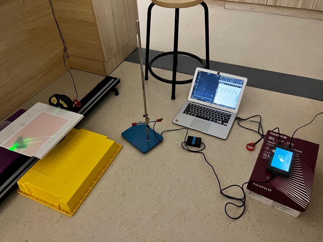
Figure 4. Labeled image of apparatus setup for the experiment (Image taken by the author of the paper)
4. Results and analysis
Table 1 is a collection of processed data that includes the directly experimentally measured illuminance of reflected light and the theoretically calculated reflected illuminance using Equation \( (15) \) at each \( {θ_{i}} \) . The rest of this paper analyzed and evaluated this set of data to lead to a meaningful conclusion. Figure 6 is a plot of \( {E_{{v_{r}}}} \) vs. \( {θ_{i}} \) data in Table 1. In Figure 5, the two curves share very similar shapes: as the angle of incidence increases from 0 to \( \frac{π}{2} \) , the reflected illuminance increases, and its rate of change also increases. However, the curve of experimental data points has a slightly higher growth rate with respect to the angle of incidence than the curve of theoretical data points, being more and more obvious after \( {θ_{i}} \) > 1.0. For the curve fit of experimental data points, most data points’ box of uncertainty intersects with the curve, which indicates a high precision. However, the two curves have a certain vertical distance between them, and this shows the deviation of experimental results from the theoretical. With these inspections, it is important to evaluate the difference between \( {E_{{v_{0}}}} \) for each set of data, given that the two sets of data are similar in shape but different in “height”.
Table 1. Processed data table of experimental and calculated reflected illuminance \( {E_{{v_{r}}}} \) / \( lx \) vs. angle of incidence \( {θ_{i}} \) .
\( {\bar{θ}_{i}} \) / rad | \( {σ_{{\bar{θ}_{i}}}} \) / rad | Experimentally Determined | Theoretically Calculated | ||
\( {\bar{{E_{v}}}_{r}} \) / \( lx \) | \( {σ_{{\bar{{E_{v}}}_{r}}}} \) / \( lx \) | \( {\bar{{E_{v}}}_{r}} \) / \( lx \) | \( {σ_{{\bar{{E_{v}}}_{r}}}} \) / \( lx \) | ||
0.13 | 0.04 | 911.8 | 251.3 | 2341.0 | 46.6 |
0.23 | 0.04 | 1020.2 | 199.9 | 2404.4 | 71.8 |
0.38 | 0.04 | 1138.8 | 177.2 | 2588.9 | 119.7 |
0.49 | 0.04 | 1191.6 | 180.5 | 2808.5 | 161.4 |
0.63 | 0.04 | 1500.6 | 251.7 | 3256.3 | 225.1 |
0.77 | 0.03 | 1941.0 | 78.5 | 3942.2 | 294.6 |
0.92 | 0.03 | 2817.1 | 184.0 | 5157.8 | 374.6 |
1.03 | 0.02 | 4226.5 | 93.0 | 6681.9 | 434.2 |
1.16 | 0.02 | 6736.5 | 376.1 | 9268.9 | 534.2 |
1.33 | 0.03 | 13181.0 | 211.6 | 15589.8 | 1632.0 |
Figure 5. Graph of experimental and calculated illuminance of reflected light \( {E_{{v_{r}}}} \) / lx versus angle of incidence \( {θ_{i}} \) .
The equation of the curve fit of experimental data points on Figure 5 with the formula \( {{E_{v}}_{r}}({θ_{i}}) \) from Equation \( (15) \) analyzed with Logger Pro is given by
\( {{E_{v}}_{r}}({θ_{i}})=a(\frac{{sin^{2}}{(arcsin{(csin{{θ_{i}}})}-{θ_{i}})}}{{sin^{2}}{(arcsin{(csin{{θ_{i}}})}+{θ_{i}})}})+b(\frac{{tan^{2}}{(arcsin{(csin{{θ_{i}}})}-{θ_{i}})}}{{tan^{2}}{(arcsin{(csin{{θ_{i}}})}+{θ_{i}})}})+d\ \ \ (16) \)
where \( a=3.5×{10^{5}}±18.3 \) , \( b=1.194×{10^{6}}±18.3 \) , \( c=-8.701×{10^{-4}}±7.088×{10^{-6}} \) , and \( d=-1.548×{10^{6}}±18.3 \) , all of which are constants from controlled variables. Since \( {E_{{v_{r}}}}({θ_{i}}=0) \) is undefined, \( {E_{{v_{0}}}} \) is approached as below.
\( \underset{{θ_{i}}→{0^{+}}}{lim}{{{E_{v}}_{r}}({θ_{i}})}=2310.471±48.941 lx\ \ \ (17) \)
\( \underset{{θ_{i}}→{0^{+}}}{lim}{{{E_{v}}_{r}}({θ_{i}})}=1383.101±98.958 lx\ \ \ (18) \)
Percentage uncertainty of \( {E_{{v_{0}}}} \) :
\( \%uncertainty=\frac{σ}{central value}=\frac{98.958}{1383.101}≈7.15\%\ \ \ (19) \)
Percentage error of \( {E_{{v_{0}}}} \) :
\( \%error=\frac{(2310.471±48.941)-(1383.101±98.958)}{(2310.471±48.941)}≈40.14\%±7.25\%\ \ \ (20) \)
Obviously, as seen in Equations \( (19) \) and \( (20) \) , the percentage error is much larger. Moreover, the difference in the two \( {E_{{v_{0}}}} \) is also much larger than each of their own errors. This suggests that significant systematic errors must be present in the conducted experiment that contributed to the large deviation from the theoretical values besides from the potential random errors. From the inspections on the shape of the curves in Figure 5, the systematic errors should have caused an overestimation of calculated \( {E_{{v_{r}}}} \) or an underestimation of experimental \( {E_{{v_{r}}}} \) .
Figure 6 shows that the derivative of the experimental curve is close but lower than the derivative of the theoretical curve initially and is then boosted rapidly after around \( {θ_{i}}= \) 1.24. This unusual trend in the rate of change of the illuminance of reflected light with respect to the angle of incidence indicates that there must be random or systematic errors or both that cause the illuminance of reflected light to be unexpectedly much higher after some \( {θ_{i}} \) get larger than 1.2 or unexpectedly much lower after some \( {θ_{i}} \) get lower than 1.25.
Figure 6. Graph of derivatives of the experimental curve and theoretical curve.
The predominating random errors in this experiment should be the fluctuations of light intensity from the laser as well as inaccuracies in the angle of incidence. The former is almost inevitable and can be minimized with more trials of experiments conducted while the latter can be prevented with improved experimental design.
Considering the discrepancy between the calculated and experimental curves in Figure 6, there could be systematic errors in the direct measurement of illuminance. The sensor chip of the light sensor used in the experiment is of squared shape, while the beam of the laser is circular. It is also observed that the beam did not completely cover the chip. This incomplete coverage can cause fluctuations in the illuminance measured. Besides, the beam of laser probably did not touch the light sensor chip perpendicularly since the position and orientation of the sensor are adjusted manually, which can cause lower experimental illuminance measurements for larger angles. Lastly, the polarizer used is not an ideal polarizer. Since the distances between the transmission axis of the polarizer are never short enough, there are always small amplitudes of EM waves passing through at an angle with the axis. This slightly increases the illuminance of light measured and overestimates the theoretical curve.
A potential improvement in the experimental design is to set up the laser and light sensor on a circular track so that their distance to the glass block is identical, making the measurement of \( {θ_{i}} \) and \( {θ_{r}} \) simpler and more accurate. With this improvement made, the problem of incomplete coverage of the sensor with a light beam can be resolved because the results can still be accurate and precise to make valid conclusions as long as the ratio of coverage is consistent for all illuminance measurements. This means that a new controlled variable, the area on the sensor chip of the light sensor being hit by the reflected light beam, can be used to help obtain more accurate results.
5. Conclusion
In this paper, the author explores how the angle of light incidence on a glass block affects the illuminance (lx) of the reflected light. As seen from the collected and analyzed data above, it is found that as the angle of the light incidence on a glass block increases, both the illuminance (lx) of the reflected light and the rate of change of the illuminance (lx) of the reflected light increase. This conclusion agrees with the hypothesis as well.
The methodologies and results for the conducted experiment are, to a large extent, reliable for a valid conclusion to be made. Furthermore, while the experimental results are highly precise, they are not highly accurate due to the presence of random and systematic errors within the conducted experiment.
This investigation is significant in that its results can be extended by generalizing the relationship between the intensity of reflected light and the angle of incidence between media of different refractive indices. Moreover, the controlled variables in this experiment are all measured and determined experimentally. This allowed more rigorous and accurate experimental results while the theory was tested because it ensured that all the data came from one context or one experimental environment.
One limitation of this paper is that Equation \( (15) \) derived by the author is too complicated to be differentiated, so the derivatives of the equation and the curves in Figure 5 are not calculated but only shown graphically in Figure 6. This means that instead of any quantified comparisons, only rough comparisons can be made for deeper analysis. In addition, the experiment was designed in such a way that the light sensor needs to be manually set up and orientated towards the reflected light beam (refer to Figure 4). This process not only takes a longer time and might cause human errors, but also it can result in systematic errors, where the sensor is orientated in such a way that the reflected light beam does not cast on the light sensing chip of the sensor exactly perpendicularly. This can affect the light intensity measured and the precision of data collected.
The results and conclusions in this paper about the illuminance of reflected light can be used and tested with a variety of materials using the general formula from Equation \( (13) \) . While it is successfully verified that there is a positive relationship between the reflected illuminance and the angle of incidence, the rate of change of this relationship is yet to be determined, and there are still many controlled variables fixed in this experiment that can be investigated and integrated to help gain a comprehensive understanding of the reflectance of light.
Acknowledgement
I would like to show my appreciation to Mr. Baldeep Sawhney, who instructed and assisted me in the conduction of the experiments for this investigation and the completion of this paper. I would also like to thank Keystone Academy for providing me the opportunity to compose this paper.
References
[1]. How to convert lux to watts (n.d.). Retrieved August 5, 2022, from https://www.rapidtables.com/calc/light/how-lux-to-watt.html#:~:text=Lux%20and%20watt% 20units%20represent,t%20convert%20lux%20to%20watts.
[2]. Peatross, J. and Ware, M. (2019). Physics of light and Optics. Brigham Young University, Department of Physics.
[3]. Zaporozhchenko-Zymaková, A., Kutnyakhov, D., Medjanik, K., Tusche, C., Fedchenko, O., Chernov, S., Ellguth, M., Nepijko, S. A., Elmers, H. J. and Schönhense, G. (2017). Momentum-resolved photoelectron absorption in Surface Barrier Scattering on Ir(111) and Graphene/IR(111). Physical Review B, 96(15). doi:10.1103/physrevb.96.155108.
[4]. Paschotta, D. R. (2012). Conflicting definitions of s and P Polarization. The Photonics Spotlight. Retrieved October 5, 2022, from https://www.rp-photonics.com/spotlight_ 2012_03_03.html#:~:text=Usually%2C%20p%2Dpolarized%20light%20is,perpendicular%2C%20p%20%3D%20parallel.
[5]. Bhattacharjee, P. R. (2005). The generalized vectorial laws of reflection and refraction. European Journal of Physics, 26(5), 901–911. doi:10.1088/0143-0807/26/5/022.
[6]. Hung, K.-Y., Wu, P.-H., Tsai, T.-W., Shye, D.-C. and Wu, H.-chien. (2009). Application of fresnel equations to improve interface reflection of inclined exposure and develop micro-mirrors for blu-ray dvds. 2009 IEEE International Conference on Industrial Technology. doi:10.1109/icit.2009.4939491.
[7]. Sen, A. (2021). Fresnel equations for Reflection & transmission | elaborate lesson | ready notes for exam. | YouTube. Retrieved September 16, 2022, from https://www. youtube.com/watch?v=AbD--ZGql8Q.
Cite this article
Chen,Z. (2024). Investigation on angle of incidence and light reflectance. Theoretical and Natural Science,34,33-41.
Data availability
The datasets used and/or analyzed during the current study will be available from the authors upon reasonable request.
Disclaimer/Publisher's Note
The statements, opinions and data contained in all publications are solely those of the individual author(s) and contributor(s) and not of EWA Publishing and/or the editor(s). EWA Publishing and/or the editor(s) disclaim responsibility for any injury to people or property resulting from any ideas, methods, instructions or products referred to in the content.
About volume
Volume title: Proceedings of the 3rd International Conference on Computing Innovation and Applied Physics
© 2024 by the author(s). Licensee EWA Publishing, Oxford, UK. This article is an open access article distributed under the terms and
conditions of the Creative Commons Attribution (CC BY) license. Authors who
publish this series agree to the following terms:
1. Authors retain copyright and grant the series right of first publication with the work simultaneously licensed under a Creative Commons
Attribution License that allows others to share the work with an acknowledgment of the work's authorship and initial publication in this
series.
2. Authors are able to enter into separate, additional contractual arrangements for the non-exclusive distribution of the series's published
version of the work (e.g., post it to an institutional repository or publish it in a book), with an acknowledgment of its initial
publication in this series.
3. Authors are permitted and encouraged to post their work online (e.g., in institutional repositories or on their website) prior to and
during the submission process, as it can lead to productive exchanges, as well as earlier and greater citation of published work (See
Open access policy for details).
References
[1]. How to convert lux to watts (n.d.). Retrieved August 5, 2022, from https://www.rapidtables.com/calc/light/how-lux-to-watt.html#:~:text=Lux%20and%20watt% 20units%20represent,t%20convert%20lux%20to%20watts.
[2]. Peatross, J. and Ware, M. (2019). Physics of light and Optics. Brigham Young University, Department of Physics.
[3]. Zaporozhchenko-Zymaková, A., Kutnyakhov, D., Medjanik, K., Tusche, C., Fedchenko, O., Chernov, S., Ellguth, M., Nepijko, S. A., Elmers, H. J. and Schönhense, G. (2017). Momentum-resolved photoelectron absorption in Surface Barrier Scattering on Ir(111) and Graphene/IR(111). Physical Review B, 96(15). doi:10.1103/physrevb.96.155108.
[4]. Paschotta, D. R. (2012). Conflicting definitions of s and P Polarization. The Photonics Spotlight. Retrieved October 5, 2022, from https://www.rp-photonics.com/spotlight_ 2012_03_03.html#:~:text=Usually%2C%20p%2Dpolarized%20light%20is,perpendicular%2C%20p%20%3D%20parallel.
[5]. Bhattacharjee, P. R. (2005). The generalized vectorial laws of reflection and refraction. European Journal of Physics, 26(5), 901–911. doi:10.1088/0143-0807/26/5/022.
[6]. Hung, K.-Y., Wu, P.-H., Tsai, T.-W., Shye, D.-C. and Wu, H.-chien. (2009). Application of fresnel equations to improve interface reflection of inclined exposure and develop micro-mirrors for blu-ray dvds. 2009 IEEE International Conference on Industrial Technology. doi:10.1109/icit.2009.4939491.
[7]. Sen, A. (2021). Fresnel equations for Reflection & transmission | elaborate lesson | ready notes for exam. | YouTube. Retrieved September 16, 2022, from https://www. youtube.com/watch?v=AbD--ZGql8Q.