


1. Introduction
Flexible stretch sensors are used in a wide range of application scenarios, such as human movement recognition, machine sensing, etc [1, 2]. At present, flexible stretch sensors are mainly divided into two categories: resistive flexible stretch sensors and capacitive flexible stretch sensors [3, 4]. The GF value of resistive flexible stretch sensors is difficult to obtain effective improvement, generally around one point several, and the sensitivity is limited. In contrast, capacitive stretch sensors possess fewer limitations and higher GF values.
The traditional methods of increasing GF value for resistive flexible stretch sensors are coating the sensor surface with conductive materials, stacking the sensors, using highly sensitive materials and using piezoresistors, which are more limited [5]. Capacitive tensile sensors are relatively more malleable and there are many ways to increase the GF value. For example, Zhou Guopeng et al. fabricated a flexible joint curvature sensor [6], which proposed a multi-stage conductive fabric sensor, i.e., a silicone material that does not pass the Young’s modulus was used to increase the GF value of the capacitive sensor. Another strategy is based on the application of metamaterial design - i.e., negative Poisson’s ratio structures [7, 8]. It has the property of stretching and expanding, so it has also been attempted to be used in the design of sensors. For example, X. Chen, M. S. Kim. and W. Yan have designed resistive tensile sensors with negative Poisson’s ratio structure and experimentally proved their superiority over the tensile sensors with conventional structure [2, 9, 10]. However, the defect of poor linearity of resistive sensors is still not well solved.
In order to improve the sensitivity and linearity of the sensor, this paper proposes a capacitive stretching sensor based on a negative Poisson’s ratio structure. The sensor designed in this paper utilizes a concave hexagonal negative Poisson’s ratio structure to improve the sensor and uses liquid metal as the electrode material. In the paper, the negative Poisson’s ratio structure is first modeled and finite element analysis is carried out using Comsol Multiphysics software; then the molds required to fabricate the sensor are designed using solidworks; finally a sensor is prepared and tested. The detailed modeling and experimental details are given below.
2. Method
2.1. Sensor Design
In this paper, capacitive sensors have been used for the fabrication and experimental work of flexible tensile sensors. In the design session, the capacitance formula was analyzed to derive that the capacitance capacity is inversely proportional to the capacitance cross-sectional area. If there is a need to maximize the magnitude of change in capacitance capacity, a structure that is not affected by the radial shrinkage effect of the material needs to be used.
In the paper [11], a concave hexagonal negative Poisson’s ratio structure is mentioned, in which the absolute value of Poisson’s ratio is highest for the concave hexagonal negative Poisson’s ratio structure with an initial angle of 60 degrees. However, in order to maintain the engineering feasibility, this paper finally chooses the concave hexagonal negative Poisson’s ratio structure with an initial angle of 45 degrees, which is not much different from the absolute value of Poisson’s ratio.
The structure of the negative Poisson’s ratio sensor designed in this paper is shown in Fig. 1, where the dielectric layer of capacitance and the negative Poisson’s ratio structure are combined together, and the sensor consists of the negative Poisson’s ratio structure, the dielectric layer, and the electrode layer. Due to the stretch-expansion property of the negative Poisson’s ratio structure, its strain in the width direction increases when it is stretched along the length direction, so it can compensate for the decrease in the area of the capacitive sensor due to the necking phenomenon, thus achieving the purpose of improving the performance of the sensor.
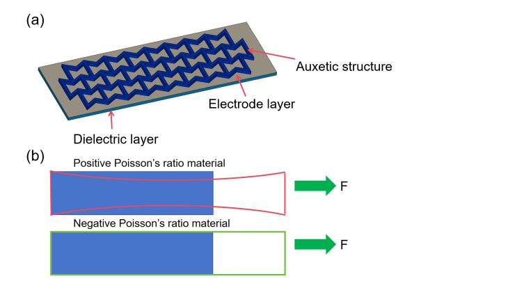
Figure 1. Structure and working principle of negative Poisson’s ratio sensor
As shown in Figure 2, a concave hexagonal negative waveform ratio structure is designed using Solidworks. In this design, we have used a three-column arrangement of cells to ensure that most of the cells are able to be subjected to lateral stretching.
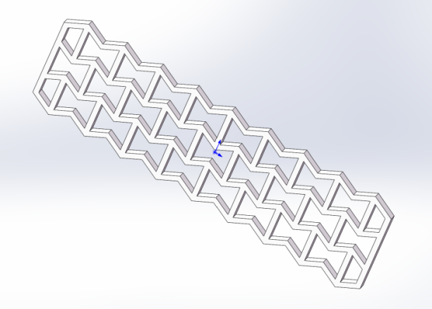
Figure 2. The 3D design drawing of Negative Poisson’s ratio structure in Solidworks
2.2. Materials and Preparation
In this paper, it was decided to use pouring to complete the main structure in terms of sensor fabrication. Firstly, A silica gel with a Shore hardness of 30duro and B silica gel were mixed in the ratio of 1:1, stirred for 3min to make the mixture homogeneous, and poured into the mold to ensure that no air bubbles appeared. The mold was made by 3D printing of red wax material, with a size of 2.4cm × 5.9cm, divided into two layers: the first layer is a negative Poisson’s ratio structure, and the second layer is a dielectric layer. First, the configured five-degree silica gel was poured into the first layer of the mold, put it into the heating table, set the temperature to 60 degrees, and wait for 20 min without demolding. Then in the middle of the mold coated with liquid metal, to ensure that the negative Poisson’s ratio structure of the upper layer of the liquid metal and full contact and evenly coated, and then connected to the wire, to ensure that the wire and the liquid metal in good contact with the wire, continue to the Shore hardness of 35duro A silicone and B silicone in accordance with the ratio of 1:1 mixing, stirring for 3min to make the mixture homogeneous, and then poured into the second layer of the mold into a heating table, set the temperature at 60 degrees Celsius, wait for 20min, take out and demold. Figure 3 shows the fabrication process of the sensor.
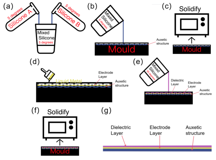
Figure 3. Preparation process
Figure 4 shows the 3D design and physical drawing of the mold. We designed the mold with a negative Poisson’s ratio structure using Solidworks 3D design software. We designed and manufactured the molds using a high-precision 3D printer with a precision of 50 microns, and the mold material is light-cured red wax.
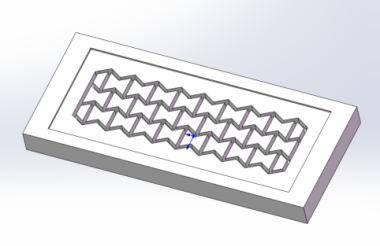
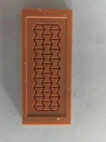
Figure 4. Negative Poisson’s ratio structural molds and physical drawings
The prepared sensor is shown in Fig. 5 with dimensions of 1.6 cm X 5 cm and its upper and lower electrodes are connected with metal wires in order to realize the measurement of the capacitance value.
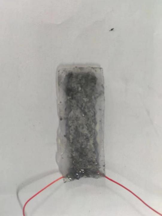
Figure 5. The sensor
3. Model
In this paper, a strain-aware model and a negative Poisson’s ratio structure model are established. By constructing the strain-aware model, the role of the capacitance change rate is analyzed by analyzing the change of the effective area of the negative Poisson’s ratio structure after the force is applied. By constructing the negative Poisson’s ratio structural model, the Young’s modulus of the sensor made of mixed materials is found out by using the average law, and the reliability of the sensor is finally analyzed.
3.1. Sensor Equivalent Mechanical Modeling
Figure 6 below illustrates one cell of the inner concave hexagonal negative Poisson’s ratio structure.
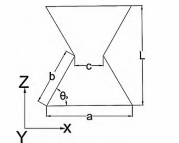
Figure 6. Negative Poisson’s ratio meta-cellular structure
As shown in Fig. 6, a, b, and c are constants representing the length of the bottom edge, the length of the hypotenuse, and the width of the cell ribs of the inner concave hexagonal negative Poisson’s ratio structure, respectively, and θ0 is the degree of the angle between the bottom edge and the hypotenuse of the inner concave hexagonal negative Poisson’s ratio structure. According to the literature [2], the Poisson’s ratio of the inner concave hexagonal negative Poisson’s ratio structure is obtained as follows:
\( {υ_{a}}=\frac{bsin{{θ_{0}}}(sin{{θ_{0}}}-cos{θ})}{(a-bcos{{θ_{0}}})(sin{{θ_{0}}}-sin{θ})}\ \ \ (1) \)
It is mentioned in the literature [9] that the equivalent Young’s modulus of a two-dimensional negative Poisson’s ratio structure satisfies the following relationship:
\( {E_{a}}/{E_{s}}=ρ/{ρ_{s}}\ \ \ (2) \)
Where \( {E_{a}} \) refers to the Young’s modulus of the negative Poisson’s ratio material, ρ refers to the structural density, and \( {ρ_{s}} \) refers to the material density. The negative Poisson’s ratio model constructed in this paper is in two-dimensional form without considering the thickness (regarded as equal thickness), then the density ratio can be equated to the area ratio, that is:
\( ρ/{ρ_{s}}=A/{A_{s}}\ \ \ (3) \)
Therefore, under the negative Poisson’s ratio model constructed in this paper, the negative Poisson’s ratio structure is satisfied:
\( E/{E_{s}}=A/{A_{s}}\ \ \ (4) \)
Rewriting the equation, the Young’s modulus of the negative Poisson’s ratio structure is as follows:
\( {E_{a}}=\frac{{A_{a}}}{{A_{s}}}{E_{s}}\ \ \ (5) \)
It is known that the Young’s modulus and Poisson’s ratio of the dielectric layer material are Eb,vb, respectively. Here, we use the averaging law to solve for the equivalent Young’s modulus, Ee, and Poisson’s ratio, ve, of the composite material with the following expressions:
\( {E_{e}}=\frac{{V_{a}}}{V}{E_{a}}+\frac{{V_{b}}}{V}{E_{b}}\ \ \ (6) \)
\( {υ_{e}}=\frac{{V_{a}}}{V}{υ_{a}}+\frac{{V_{b}}}{V}{υ_{b}}\ \ \ (7) \)
Where Va and Vb are the volumes of the negative Poisson’s ratio structure and the dielectric layer material, respectively, and V is the total volume of the composite.
According to Hooke’s law, S is the area over which the boundary load acts, and assuming that the tension in the z-axis direction is ∂z, the strain in the z-axis direction is ℇz, and Ee is a constant, the strain in the z-direction can be expressed as:
\( {ε_{z}}=\frac{{σ_{z}}}{{E_{e}}} \ \ \ (8) \)
According to the defining equation of Poisson’s ratio, there are:
\( {ν_{e}}=-\frac{{ε_{x}}}{{ε_{z}}}\ \ \ (9) \)
Rewriting Eq. (9), the strain of the sensor along the x-axis can be expressed as:
\( {ε_{x}}=-{ε_{z}}{υ_{e}}\ \ \ (10) \)
3.2. Capacitive sensing model
Assuming that the length and width of the liquid metal capacitance part of the flexible tensile sensor are L0 and W0 respectively, the Poisson’s ratio is ve, the initial thickness of the dielectric layer is d0, and the elastic silica gel is regarded as isotropic and incompressible. The capacitance part of the dielectric constant and dielectric elastomer volume is unchanged, L0 is the initial length of the liquid metal capacitance, W0 is the initial width of the liquid metal capacitance, d0 is the initial thickness of the dielectric layer, then there are:
\( {L_{0}}{W_{0}}{d_{0}}=LWd\ \ \ (11) \)
Where the constant L0 is the initial length of the liquid metal capacitor, ε is the strain of the sensor, and νe is the Poisson’s ratio of the liquid metal capacitor (unchanged during stretching); then L0(1+νe) is the length of the sensor after stretching. According to the tangential strain of the liquid metal capacitance is calculated as the width of the liquid metal capacitance after stretching is W0(1-νeε), because this paper uses the negative Poisson’s ratio structure as the main structure of the flexible tensile sensor, the tangential strain is opposite to the strain generated in the direction of the stretching, and the width of the liquid metal capacitance after being subjected to the stretching is W0(1+νeε). So its thickness after being subjected to stretching becomes:
\( d=\frac{{d_{0}}}{(1+{ε_{z}})(1+{ε_{x}})}\ \ \ (12) \)
Initially, the capacitance value is:
\( C={ε_{0}}{ε_{r}}\frac{{L_{0}}(1+{ε_{z}}){W_{0}}(1+{ε_{x}})}{d}\ \ \ (13) \)
Substituting Eq. (2) gives the value of capacitance after stretching as:
\( C=\frac{{ε_{0}}{ε_{r}}{W_{0}}(1-{v_{e}}{ε_{z}}{)^{2}}{L_{0}}(1+{ε_{z}}{)^{2}}}{{d_{0}}}\ \ \ (14) \)
The rate of change of capacitance is known to be ∆C/C0, which is obtained by substituting it into the substitution equation (14):
\( \frac{ΔC}{{C_{0}}}=\frac{C-{C_{0}}}{{C_{0}}}=(1+{ε_{z}}{)^{2}}(1+{ε_{x}}{)^{2}}-1\ \ \ (15) \)
The expansion of Eq. 15 into a 4th order polynomial can be simplified by omitting the 3rd and 4th order terms:
\( \frac{ΔC}{{C_{0}}}=\frac{C-{C_{0}}}{{C_{0}}}=(1+{ε_{z}}{)^{2}}(1+{ε_{x}}{)^{2}}-1\ \ \ (16) \)
The sensitivity coefficient s and the GF value of the capacitive sensor are defined as follows, respectively:
\( s=\frac{ΔC}{ΔL}\ \ \ (17) \)
\( GF=\frac{ΔC{L_{0}}}{{C_{0}}ΔL}\ \ \ (18) \)
4. Footnotes Numerical and finite element analysis
4.1. Numerical Analysis
Using the mathematical model in Chapter 3, we can calculate the capacitance change results of the improved sensor numerically. In this paper, we used matlab software for programming (see attached for the program) to simulate and compare the rate of change of capacitance of the improved sensor and the conventional sensor after being stretched by force. As shown in Fig. 7, the improved sensor has a higher rate of change of capacitance for the same stretching length, implying that the sensor proposed in this paper is more sensitive.
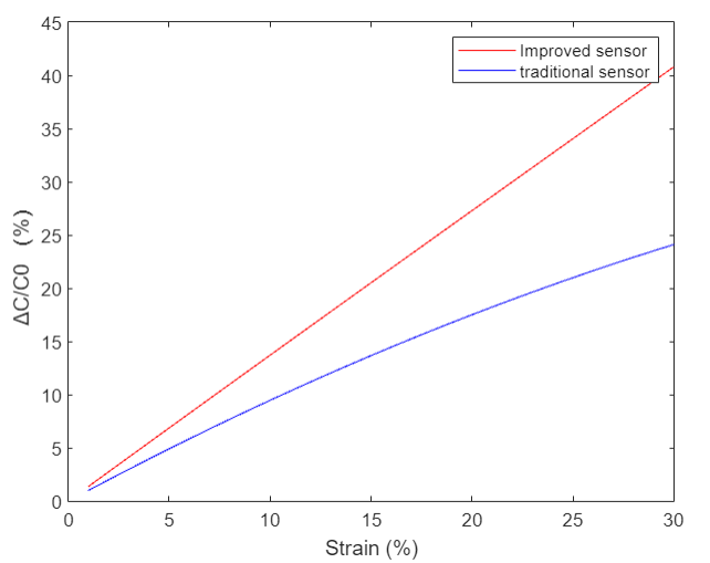
Figure 7. Comparison of numerical calculations of the rate of change of capacitance of the improved sensor with that of the conventional sensor
Figure 8 shows the effect of the initial angle of the negative Poisson structural ratio cell on the Poisson’s ratio. Assuming that a and b in Figure 5 are kept constant and only the angles of the two edges are changed. Another initial angles of 30, 45 and 60 degrees, respectively, the change in negative Poisson’s ratio can be calculated and its absolute value increases with the increase of the angle.
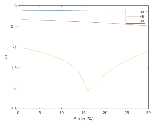
Figure 8. Poisson’s ratio of the negative Poisson’s ratio structure for different initial angles and different strains va
1.1. Finite Element (FEM)Analysis
The following simulation results were obtained by importing the stl file of the negative Poisson’s ratio structure in COMSOL, adding the Silicone material property and applying a boundary load of 100N/m2 at one of the ends. Visual inspection found that the negative Poisson’s ratio structure did not occur radial shrinkage effect, with the characteristics of negative Poisson’s ratio structure.
The simulation parameters of the model include: the Young’s modulus of the negative Poisson’s ratio material is 450 kPa; the Young’s modulus of the dielectric layer material is 250k Pa; the boundary load is 1N; and in order to perfectly simulate the tensile behaviour of the silica gel material, we adopt the intrinsic model of the superelastic material. In this simulation, we use the second-order M-R model, and its model parameters C0, C1 are 1.1X10⁵ and 0.12X10⁵, respectively.
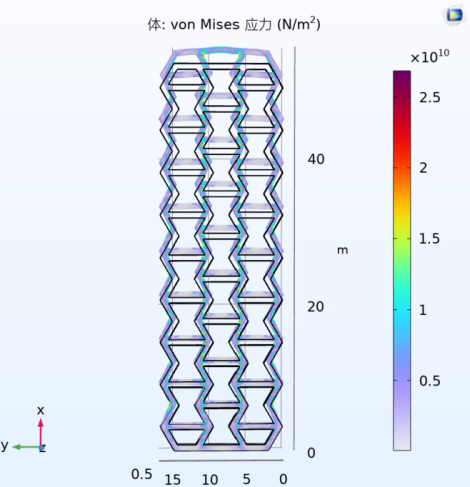
Figure 9. Tensile simulation of negative Poisson’s ratio structure
We simulated the tensile effect of the negative Poisson’s ratio sensor architecture and obtained the tensile displacement output of each part of the sensor by setting the displacement of the tensile surface to 10 mm. As can be observed from Fig. 10, the necking phenomenon of the sensor in the y-axis direction is effectively suppressed after the improvement using the negative Poisson’s ratio architecture.
|
|
(a) Advanced Structure | (b) Conventional Structure |
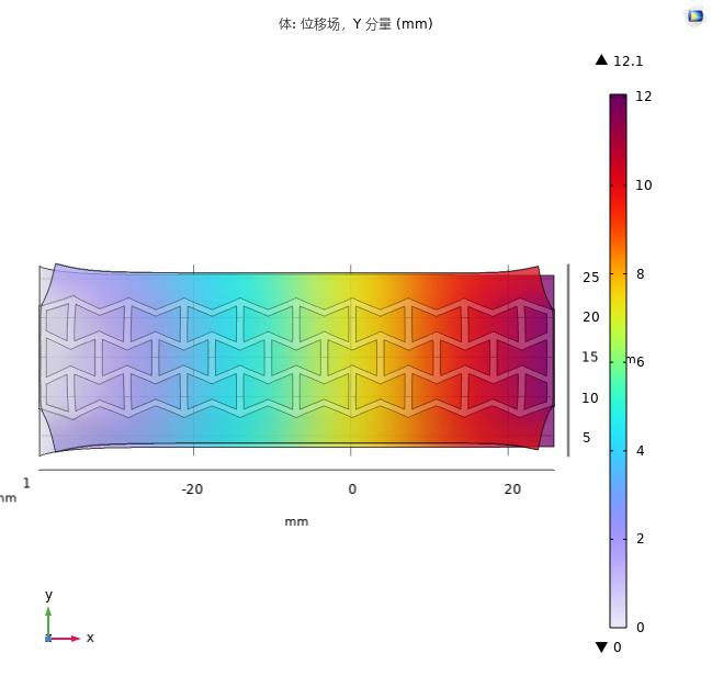
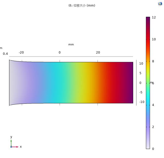
Figure 10. Comparison of negative Poisson’s ratio structure with conventional sensor tensile simulation
5. Experimental Results and Discussion
In this chapter, a series of experiments were designed to complete the testing in order to verify the excellent performance of the negative Poisson’s ratio structured capacitance sensor. The experimental equipment used include a tensile test bench, a tensiometer, a high-precision capacitance meter, a millimeter-precision straightedge, and a real-time module for commercial tiny capacitance measurements (including demo software).
As shown in Figure 11, the negative Poisson’s ratio structure was stretched as expected without the radial shrinkage effect of the conventional structure.
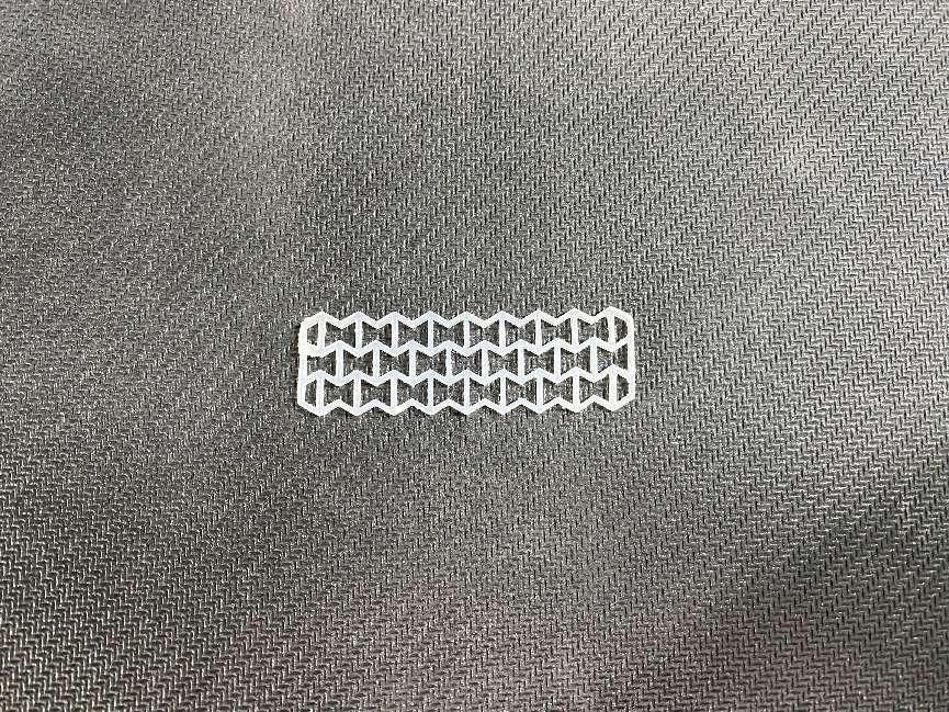
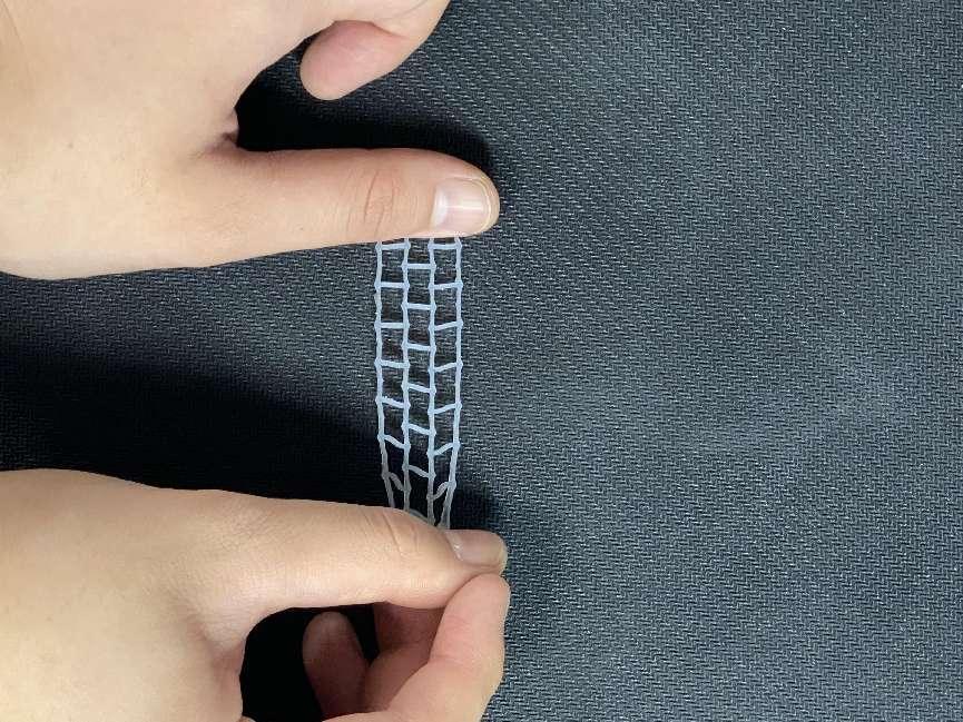
Figure 11. Tensile test of negative Poisson’s ratio structure
Figure 12 shows the tensile stress test rig used, which we utilized to test the basic tensile properties of the prepared capacitors. The tensile force test rig consists of a motorized tensile stage, fixtures (to hold the tensile transducer) and a tensile force tester. The initial value of the capacitor, C0, was measured to be 48.3 pF and the initial length of the capacitor, L0, was 53 mm.
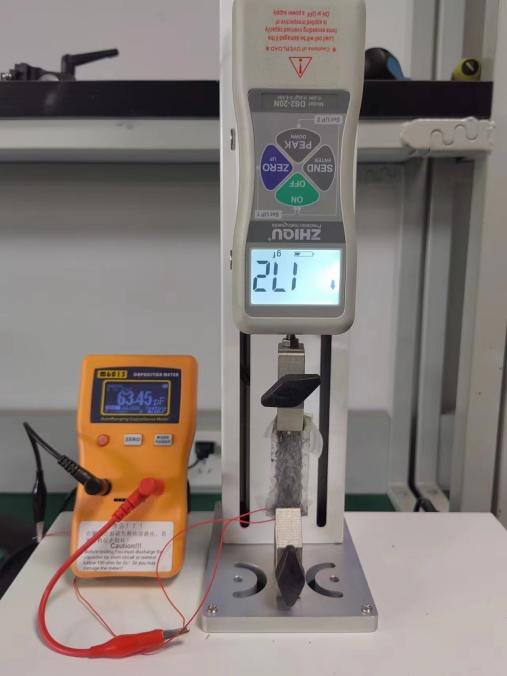
Figure 12. Basic tensile test setup
We used a high-precision capacitance tester to measure the capacitance change value under different stretch length variations. The data are shown in Figure 12, and the capacitance change value reaches 35 pf at a length change of 1.75 cm. According to equations (17) and (18), using the data in Fig. 13, we can calculate the sensitivity s of the sensor to be 2 pf/mm, and the GF value is 2.19.
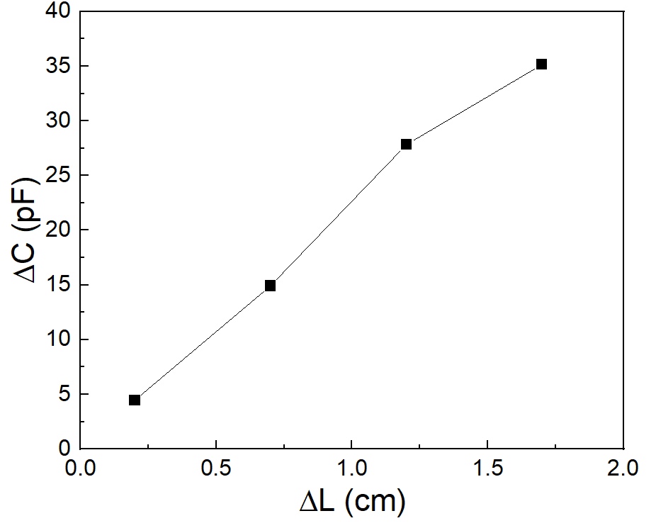
Figure 13. Basic stretching data
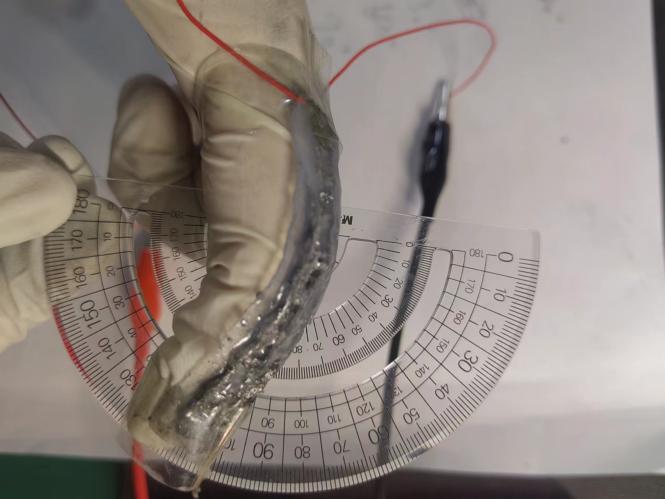
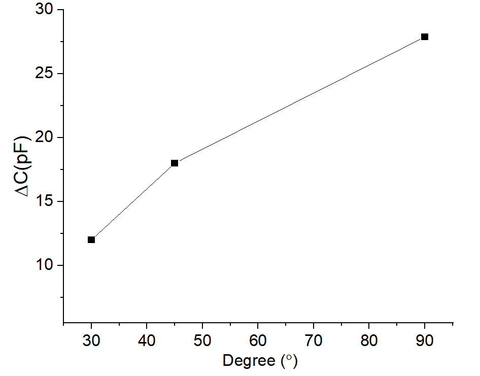
Figure 14. Tension sensor applied to finger flexion joint measurement
We used a tiny capacitance measurement module to monitor the real-time changes in the finger joints, and Figure 14 shows the real-time bending angle data of the middle joint of the index finger using its host computer software, which we measured for 30, 45 and 90 degrees of finger flexion, respectively.
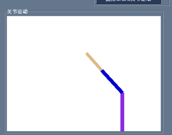
Figure 15. Dynamic display of joint movements.
Figure 15 shows an animation of the joint movement demonstration obtained using the real-time monitoring software provided with the commercial measurement module. Using the improved capacitance pull sensor and measurement system, we can monitor finger flexion changes in real time. In the future, this feature is expected to be used for somatosensory measurements and robot control.
6. Conclusion
This paper first analyses other articles and concludes that the use of capacitive sensors and the use of a negative Poisson’s ratio structure with an initial angle of 45 degrees are able to improve the GF value of the sensor while taking into account the engineering difficulty. In this paper, the structure of the sensor is first designed. The capacitance includes three layers: two polar plates and a dielectric layer, which is in the middlemost layer of the whole sensor, so the negative Poisson’s ratio structure is included in the dielectric layer. The two outermost layers are protective layers. In this paper, the simulation of Comsol and Matlab is carried out for capacitive flexible tensile sensors. The sensors were also fabricated and tensile tests were performed. The main contributions of this paper include:
1.In this paper, the negative Poisson’s ratio structure is introduced into the sensor, which improves the GF value of the capacitive sensor.
2. an analytical model of capacitive sensors with negative Poisson’s ratio structure is established, which provides a basis for sensor design.
This paper is still not the best in engineering, after theoretical analysis, the initial angle of 60 degrees of negative Poisson’s ratio structure is the best. However, for the consideration of engineering difficulty, the negative Poisson’s ratio structure with an initial angle of 45 degrees was finally selected. In future work, this paper will overcome the engineering problems and continue to improve the GF value of the sensor.
References
[1]. Y. Cai, W. Huang, X. Dong.Wearable and flexible electronic strain sensor. Chinese Science Bulletin,2017,62(7):635-649.
[2]. X. Chen.Auxetic Mechanical Metamaterials to Enhance Sensitivity of Stretchable Strain Sensors.Adv. Mater. 2018, 30:1706589.
[3]. H. Liu, Qianming Li, Shuaidi Zhang, Rui Yin, Xianhu Liu.Electrically conductive polymer composites for smart flexible strain sensors: a critical review. Journal of Materials Chemistry C,2018,6:12121.
[4]. G. Zhou, R. Zhao, H. Dai. A Low-Cost Conductive-Textile Based Multifunctional Flexible Capacitive Sensor for Human Motion Tracking.IEEE International Conference on Robotics and Biomimetics, 2021, 317-321.
[5]. Y. Cai, W. Huang, X. Dong.Wearable and flexible electronic strain sensor. Chinese Science Bulletin,2017,62(7):635-649.
[6]. G. Zhou, R. Zhao, T.Liu, H.Dai. Bending Angle Mesurement for Finger Joint Based on Conductive Fabric.Chinese Journal of sensors and actuators, 2022,35(4):440-446.
[7]. Z. Wang, C. Luan, G. Liaom, J. Liu, J. Fu.Progress in Auxetic Mechanical Metamaterials: Structures, Characteristics, Manufacturing Methods, and Applications.Adv. Eng. Mater. 2020, 22, 2000312.
[8]. Surjadi Ju,L Gao,H Du,L Xiang,Xiang Xiong,Nicholas Xuanlai Fang, L Yang.Mechanical Metamaterials and Their Engineering Applications. Adv. Eng. Mater. 2019, 21, 1800864.
[9]. M. S.Kim, Y. Lee, J. Ahn, S. Kim, K. Kang, H. Lim, B. Bae, I.Park.Skin-like Omnidirectional Stretchable Platform with Negative Poisson’s Ratio for Wearable Strain–Pressure Simultaneous Sensor.Adv. Funct. Mater. 2023, 33:2208792.
[10]. W. Yan, X. Tian, D. Zhang, Y. Zhou, Q. Wang.3D Printing of Stretchable Strain Sensor Based on Continuous Fiber Reinforced Auxetic Structure.Chinese Journal of Mechanical Engineering: Additive Manufacturing Frontiers, 2023, 2, 100073.
[11]. X. Kang, J. Liu, G. Xia, Q. Xu. Design of Concave Hexagonal Auxetic Metamaterial Using Cell Topology Optimization Approach. Journal of Anhui Jianzhu University,2022,30(1):22-26.
Cite this article
Jiang,Q. (2024). Word high gauge factor flexible capacitive strain sensor based on auxetic structure. Theoretical and Natural Science,38,78-88.
Data availability
The datasets used and/or analyzed during the current study will be available from the authors upon reasonable request.
Disclaimer/Publisher's Note
The statements, opinions and data contained in all publications are solely those of the individual author(s) and contributor(s) and not of EWA Publishing and/or the editor(s). EWA Publishing and/or the editor(s) disclaim responsibility for any injury to people or property resulting from any ideas, methods, instructions or products referred to in the content.
About volume
Volume title: Proceedings of the 2nd International Conference on Mathematical Physics and Computational Simulation
© 2024 by the author(s). Licensee EWA Publishing, Oxford, UK. This article is an open access article distributed under the terms and
conditions of the Creative Commons Attribution (CC BY) license. Authors who
publish this series agree to the following terms:
1. Authors retain copyright and grant the series right of first publication with the work simultaneously licensed under a Creative Commons
Attribution License that allows others to share the work with an acknowledgment of the work's authorship and initial publication in this
series.
2. Authors are able to enter into separate, additional contractual arrangements for the non-exclusive distribution of the series's published
version of the work (e.g., post it to an institutional repository or publish it in a book), with an acknowledgment of its initial
publication in this series.
3. Authors are permitted and encouraged to post their work online (e.g., in institutional repositories or on their website) prior to and
during the submission process, as it can lead to productive exchanges, as well as earlier and greater citation of published work (See
Open access policy for details).
References
[1]. Y. Cai, W. Huang, X. Dong.Wearable and flexible electronic strain sensor. Chinese Science Bulletin,2017,62(7):635-649.
[2]. X. Chen.Auxetic Mechanical Metamaterials to Enhance Sensitivity of Stretchable Strain Sensors.Adv. Mater. 2018, 30:1706589.
[3]. H. Liu, Qianming Li, Shuaidi Zhang, Rui Yin, Xianhu Liu.Electrically conductive polymer composites for smart flexible strain sensors: a critical review. Journal of Materials Chemistry C,2018,6:12121.
[4]. G. Zhou, R. Zhao, H. Dai. A Low-Cost Conductive-Textile Based Multifunctional Flexible Capacitive Sensor for Human Motion Tracking.IEEE International Conference on Robotics and Biomimetics, 2021, 317-321.
[5]. Y. Cai, W. Huang, X. Dong.Wearable and flexible electronic strain sensor. Chinese Science Bulletin,2017,62(7):635-649.
[6]. G. Zhou, R. Zhao, T.Liu, H.Dai. Bending Angle Mesurement for Finger Joint Based on Conductive Fabric.Chinese Journal of sensors and actuators, 2022,35(4):440-446.
[7]. Z. Wang, C. Luan, G. Liaom, J. Liu, J. Fu.Progress in Auxetic Mechanical Metamaterials: Structures, Characteristics, Manufacturing Methods, and Applications.Adv. Eng. Mater. 2020, 22, 2000312.
[8]. Surjadi Ju,L Gao,H Du,L Xiang,Xiang Xiong,Nicholas Xuanlai Fang, L Yang.Mechanical Metamaterials and Their Engineering Applications. Adv. Eng. Mater. 2019, 21, 1800864.
[9]. M. S.Kim, Y. Lee, J. Ahn, S. Kim, K. Kang, H. Lim, B. Bae, I.Park.Skin-like Omnidirectional Stretchable Platform with Negative Poisson’s Ratio for Wearable Strain–Pressure Simultaneous Sensor.Adv. Funct. Mater. 2023, 33:2208792.
[10]. W. Yan, X. Tian, D. Zhang, Y. Zhou, Q. Wang.3D Printing of Stretchable Strain Sensor Based on Continuous Fiber Reinforced Auxetic Structure.Chinese Journal of Mechanical Engineering: Additive Manufacturing Frontiers, 2023, 2, 100073.
[11]. X. Kang, J. Liu, G. Xia, Q. Xu. Design of Concave Hexagonal Auxetic Metamaterial Using Cell Topology Optimization Approach. Journal of Anhui Jianzhu University,2022,30(1):22-26.