


1. Introduction
With the enhancement of environmental protection awareness and the transformation of energy structure, electric vehicles (EVs) have become the development trend of the automotive industry. Electric vehicles have the advantages of high energy efficiency, low emission and low noise, and are an important way to achieve green transportation. The power transmission system of electric vehicle is one of the key factors affecting its performance, in which the reducer, as an important part connecting the motor and the drive wheel, plays a crucial role in the speed, torque and power distribution of the vehicle. Although the single-stage reducer has a simple structure, it has limitations in meeting the requirements of high torque and wide speed ratio, especially in improving the acceleration performance and climbing ability of electric vehicles.
At present, domestic and foreign scholars have also carried out relevant research on the two-stage retarder of electric vehicles. Liu Xiaosong [1] et al. designed a two-stage reducer structure for a pure electric vehicle, adopting a parallel shaft gear structure, and conducted simulation and test research on gear parameters, bearings and reducer performance during the design process. The results show that the designed reducer meets the needs of electric vehicles and the design is reasonable. Wang Shushan [2] et al. designed the reducer of an electric vehicle with fine and high teeth, completed the design and analyzed the reducer from the aspects of structural scheme, parameter checking calculation and experimental verification. The results show that the designed reducer meets the design requirements and the noise value meets the standard. Zhang Kaixuan [3]et al carried out optimization analysis on the performance of the reducer of electric vehicles, calculated the optimal transmission ratio of electric vehicles with AVL Cruise software, and carried out strength analysis on the optimized reducer structure with ABAQUS software, and obtained corresponding conclusions. Li Jie[4] et al. proposed a method for compiling the load spectrum of the retarder of hybrid electric vehicles. Typical working conditions were selected for real vehicle data collection, and the load data under each typical working conditions were divided into 5 categories according to the power source state, and the data were pre-processed. The fatigue life prediction simulation of the gearbox gear of a hybrid electric vehicle is carried out using the compiled load spectrum and the extracted sample load as load input. Zhu Bo[5] et al established a thermal network simulation model for the gear reducer of electric vehicles, and analyzed the heat and efficiency of the gear reducer by considering the heat production and heat transfer process of each component of the gear reducer. On this basis, the secondary development sub-model is developed to realize the real-time calculation of convection coefficient based on different lubricating oil temperatures and working conditions, and the proposed method provides a good guide for the design and optimization of electric vehicle retarder.
In summary, there are more researches on electric vehicle retarders at home and abroad, but there are relatively few researches on steering retarders. Based on the working principle of electric vehicles, this paper designs a two-stage steering gear reducer suitable for electric vehicles, adopts planetary gear transmission system, and carries out relevant theoretical analysis and simulation calculation to determine the design of the steering gear reducer structure is reasonable.
2. Two-stage reducer overall scheme design
2.1. Formulation of basic parameters of two-stage reducer
There are many different types of retarders on electric vehicles, respectively acting on different positions on electric vehicles. The design parameters of the two-stage steering retarder designed in this paper are shown in Table 1.
Table 1. Design parameters of electric vehicle steering retarder
Motor power value | 600W |
Rated torque | 105N·m |
Rated speed | 3000rpm |
Rated output speed | 85rpm |
Axial load is allowed | 180N |
Allowable radial load | 900N |
Noise level | ≤65 |
Service life | For 2 years, follow 12-16 hours a day |
In electric vehicles, the steering reducer is mainly used to convert the steering operation of the vehicle driver into the steering movement of the wheel, so that the vehicle changes direction. When the driver conducts steering operations through the steering wheel, the steering wheel will transmit steering instructions to the steering reducer. The steering reducer usually contains a gear drive system, which reduces the rotation speed of the steering wheel input and increases the torque of the output through a combination of gears of different sizes. The steering motion signal after deceleration will be transmitted to the steering system of the vehicle, and finally converted into the steering movement of the wheels. In this way, the vehicle can correctly change the direction of travel according to the steering command of the driver[6].
2.2. Transmission scheme drawing
As shown in Figure 1, in the two-stage planetary gear drive reducer, the primary and secondary structure composition is basically the same. The first stage is driven by the motor, the motor shaft drives the solar wheel, the solar wheel drives the primary planetary wheel, the primary planetary wheel drives the secondary solar wheel through the planetary frame, and the secondary solar wheel drives the secondary planetary wheel. The two-stage planetary wheel rotates by the output shaft driven by the two-stage planetary frame. In this process, the primary planetary wheel and the secondary planetary wheel share an inner tooth ring.
In the electric vehicle, the input shaft drives the sun gear, the sun gear drives the planet gear to rotate, and through the meshing relationship between the planet gear and the ring gear, the speed is gradually reduced and the torque is correspondingly amplified. Finally, the reducer converts the high-speed, low-torque output of the driving motor into the low-speed, high-torque output required for steering, providing sufficient torque support for the steering system [7].

Figure 1. Planetary gear transmission scheme of two-stage reducer
3. Calculation of transmission parameters of two-stage reducer
3.1. Reduction ratio allocation
In the two-stage planetary drive reducer, the reduction ratio allocation is achieved by selecting the appropriate gear ratio. The reduction ratio is the ratio between the speed of the input shaft and the speed of the output shaft, which is used to determine the degree of speed reduction.
In general, the first stage reduction ratio determines the main reduction ratio of the overall reducer. The first stage reduction ratio will be larger to provide a larger speed reduction effect. The selection of reduction ratio can be realized by reasonably designing the number of teeth of sun gear, planet gear and ring gear. The second stage deceleration ratio is based on the first stage deceleration ratio for further deceleration. The deceleration of the second stage is generally smaller, the purpose is to further reduce the speed on the basis of the first stage, and increase the torque.
The formula for calculating the total transmission ratio of the reducer is [8].
\( i=\frac{{n_{input}}}{{n_{output}}}=\frac{3000}{85}≈35\ \ \ (1) \)
Considering the force conditions in the steering process of electric vehicles, the first-stage deceleration ratio is assigned as i1=10, and the second-stage deceleration ratio is assigned as i2=3.5.
3.2. Calculation of transmission gear number
The calculation of transmission gear number is mainly to calculate the number of solar wheels, planetary wheels and epicyclic gear trains. The calculation of the gear number of the two-stage planetary gear transmission needs to be determined according to the transmission ratio, the input and output speed and the number of planetary wheels, and the number of teeth of the planetary wheel and the sun wheel directly affects the reduction ratio of the reducer. Under normal circumstances, the number of teeth of the planetary wheel is more than that of the solar wheel to achieve the deceleration effect.
First, determine the number of teeth of the primary solar wheel and the inner gear ring, and select the number of teeth according to the requirements of non-displacement transmission. By consulting the "Mechanical Design Manual", the number of teeth of the primary gear train can be matched into Za=8, Zb=19, Zc=46.
Second stage gear distribution:
\( i_{ax}^{b}=\frac{50}{{i_{1}}}=\frac{50}{10}=5\ \ \ (2) \)
According to the requirements of non-displacement transmission, the number of teeth can be selected. By consulting the Mechanical Design Manual, it can be matched into Za=8, Zb=19, Zc=46. The actual transmission ratio is calculated as:
\( {i_{2}}=1+i_{ax}^{b}=1+\frac{{Z_{c}}}{{Z_{a}}}=1+\frac{46}{8}=6.75 \ \ \ (3) \)
The total transmission ratio is calculated as:
\( i={i_{1}}{i_{2}}=5×6.75≈33.75\ \ \ (4) \)
Overall consideration, the two-stage planetary wheel is selected with the same number of teeth, in order to achieve accurate matching of the two-stage transmission ratio. Transmission ratio accuracy is very important for some applications, and by using planetary wheels with the same number of teeth, transmission errors and imbalances can be reduced, and transmission accuracy and stability can be improved.
4. Structure design and 3D modeling of two-stage steering reducer
The 3D model of the reducer is drawn in Solid works software, and the overall schematic diagram of the 3D model is shown in Figure 2.
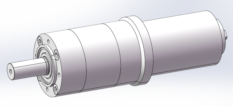
Figure 2. Schematic diagram of three-dimensional model of two-stage steering reducer
As shown in Figure 2, a three-dimensional model of the electric vehicle steering reducer structure designed in this paper, in this structure, the motor input shaft usually needs to be supported in the transmission housing to ensure its correct position and input to the gear assembly. Therefore, it is necessary to consider the fit between the input shaft and the drive housing, as well as the appropriate bearings and seals to support the input shaft and ensure its normal operation and lubrication. The fit and connection between the input shaft and the motor should also be considered. It is usually connected to the motor output shaft by means of a keyway, gear or cone connection to ensure the transmission of torque and rotational motion.
The planetary frame is a key component responsible for supporting the planetary gear and enabling it to rotate around the solar gear and move along the inner ring of the ring gear. The assembly of the output shaft of the planetary frame needs to ensure accurate fit and alignment of the axis. During the assembly process, necessary corrections and adjustments need to be made to ensure the correct operation of the planetary gear and transmission efficiency. The two-stage planetary drive drives the two-stage planetary frame output shaft to output, and the output shaft usually needs to be supported in the drive reducer to maintain its correct position and output to the gear assembly.
In this paper, the electric vehicle steering gear reducer is designed to share an inner gear ring. By sharing an inner gear ring, the total number of parts of the gear reducer can be reduced, the design and manufacturing process can be simplified, the cost can be reduced, and the coordination and rotation gap between the parts can be reduced. The sharing of internal gear rings can reduce transmission losses between gear pairs, and the overall efficiency of the reducer may be improved because there are fewer transmission interfaces.
The inner gear ring is designed with fastening screws connected to the box, and is connected to the box of the reducer through bolt fixing. Usually, the bottom of the inner gear ring is provided with mounting holes, and the inner gear ring is fixed on the box through bolts. This method is simple and effective, and can provide good connection strength and stability.
The housing design of the steering gear reducer is a key part to ensure the safe operation and good working of the internal parts of the gear reducer. First of all, it is necessary to determine the structural layout of the housing according to the internal parts layout and functional requirements of the reducer, including the shape of the housing, wall thickness, and the location of the inlet and outlet. After consulting the relevant literature, cylindrical shell is selected as the research object. The structure of the housing, including the internal and external geometry, support structure, connection holes, etc., ensure that the internal components can be well supported and fixed, and meet the needs of assembly and maintenance.
In addition, it is necessary to take into account the heat that may be generated during the working process of the reducer, and design a suitable heat dissipation structure to improve the heat dissipation efficiency, prevent parts from overheating, and affect the performance and life of the reducer. The housing is assembled to ensure that the housing is well matched with the internal parts, and the necessary debugging and inspection are carried out to ensure the performance and reliability of the reducer.
5. Reducer ROMAX simulation analysis
5.1. Pre-processing of ROMAX simulation
Using ROMAX software for reducer simulation analysis, the pre-processing work is mainly divided into the following steps:
(1) Model establishment: First of all, the reducer gear transmission system model needs to be imported into the ROMAX software. Under normal circumstances, there are two methods, one is to directly import the two-dimensional CAD drawing of the reducer, but the model needs to be repaired after the import is completed, which is more troublesome; The other is to model the reducer directly in the ROMAX software according to the three-dimensional diagram, and the project design is carried out in this way.
As shown in Figure 3, the three-dimensional model diagram of ROMAX, a two-stage planetary transmission steering reducer for electric vehicles established in ROMAX.
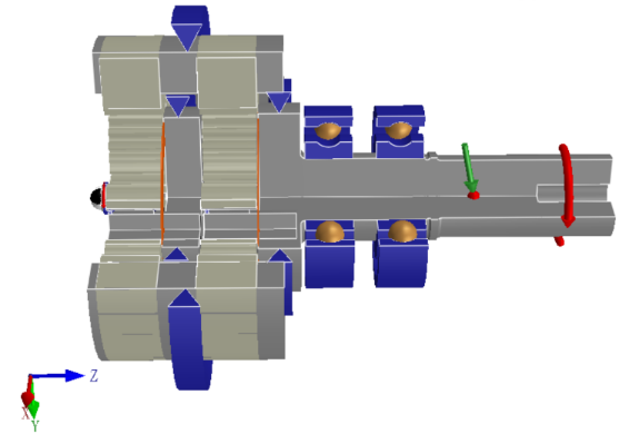
Figure 3. Three-dimensional model of ROMAX two-stage planetary transmission steering reducer
As shown in Figure 3, the model is based on the 3D model of the reducer drawn in Solidworks software in accordance with 1:1 scale modeling, the model mainly includes motor input shaft, primary gear train, secondary gear train, planetary frame output shaft and other parts.
(2) Define gear and detail: ROMAX requires detailed processing of each gear parameter, which needs to input parameters such as modulus, pressure Angle, tip circle diameter, root circle diameter, span tooth number and tooth width. This part can be entered according to the design size.
(3) Defining materials:
According to the above design content, the solar wheel material of the reducer is 20CrMnTi, the heat treatment process is carburizing, quenching and tempering, the hardening layer depth is 0.35~0.6mm, and the hardness is HRC55-60. It can be seen from the table that the contact fatigue limit is 1500MPa and the bending fatigue strength is 850MPa. Assuming that the design life (number of stress cycles) of the gear is 107, the minimum safety factor SH =1.0 and SF =1.25 under general reliability are selected to calculate the allowable contact stress of 1950MPa and the allowable bending stress of 664MPa[9].
The material of the planetary wheel is 20CrMnTi, the heat treatment process is carburizing, quenching and tempering, the depth of the hardened layer is 0.35~0.6mm, and the hardness is HRC55-60. It can be seen from the table that the contact fatigue limit is 1500MPa and the bending fatigue strength is 850MPa. Assuming that the design life (stress cycles) of the gear is 107, the minimum safety factor SH =1.0 and SF =1.25 under general reliability are selected, and the allowable contact stress is 1950MPa and the allowable bending stress is 664MPa.
The inner gear ring material is 42CrMo4, the heat treatment process is nitriding after tempering, the hardening layer depth is 0.09~0.2mm, the nitriding layer depth is 0.05-0.1mm, and the hardness is HRC45-50. It can be seen from the table that the contact fatigue limit is 1103MPa and the bending fatigue strength is 303.44MPa. The design life (number of stress cycles) of the gear is set to 107, and the minimum safety factor SH =1.0 and SF =1.25 under general reliability are selected to calculate the allowable contact stress of 1433.9MPa and the allowable bending stress of 478.85MPa.
(4) Define model boundary conditions and add bearings:
The definition of model boundary conditions should be combined with the characteristics of electric vehicles in the actual working process. The steering reducer should consider the effect of speed and torque during the actual movement, so 3000rpm speed and corresponding torque value are applied to the input shaft of the motor.
Two bearings are mainly applied on the reducer model, which act on the output shaft of the two-stage planetary frame. The type of bearings is defined as deep groove ball bearings by referring to the Mechanical Design Manual.
5.2. Pretreatment of ROMAX simulation
After the definition of the model is completed, the simulation begins. After the simulation is completed, the strength and deformation diagram of the main parts of the reducer are derived, as shown in Figure4.
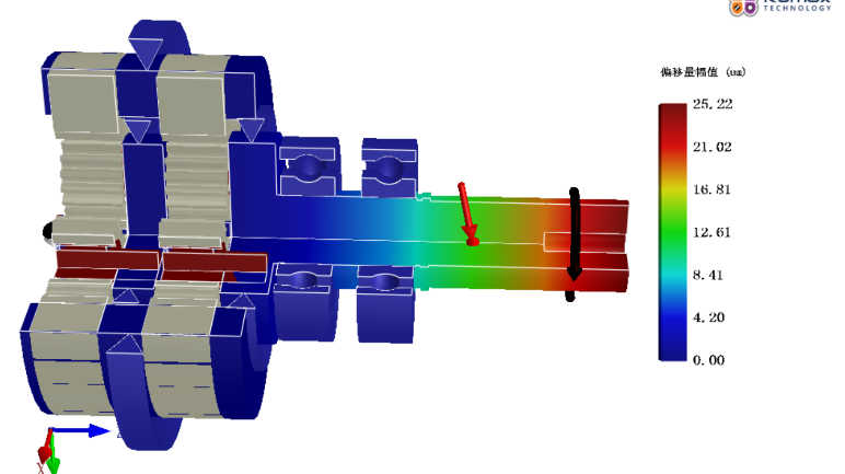
Figure 4. Overall deformation cloud image of two-stage reducer
As can be seen from Figure 4, the overall deformation value of the reducer under this working condition is 25.22um, and the deformation value is mainly at the input shaft end of the motor, and the deformation amount is small, which will not have a great impact on the overall structure of the reducer.
|
|
(a) Stress distribution on the solar gear tooth surface (left) and tooth root (right) of the primary gear train | |
|
|
(b) Stress distribution of planetary gear tooth surface (left) and tooth root (right) of first-stage gear train | |
|
|
(c) Stress distribution on the tooth surface (left) and root (right) of the inner gear ring of the first stage gear train | |
Figure 5. Stress distribution cloud map of first-order gear train | |
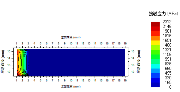
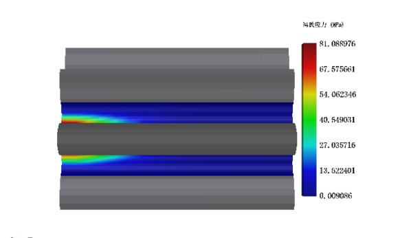
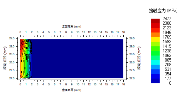
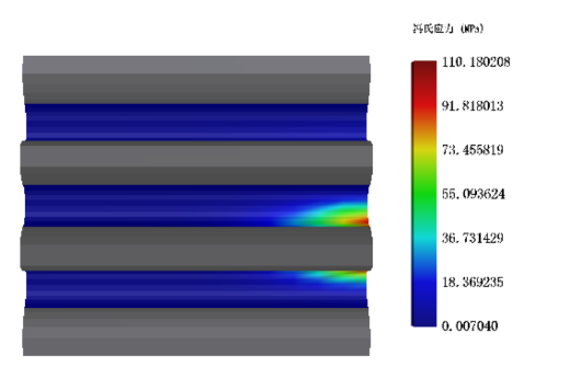
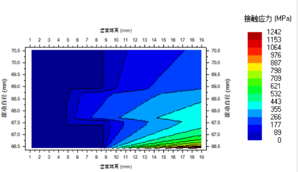
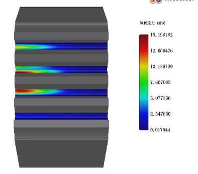
As shown in FIG. 5, under this working condition, the solar wheel, planetary wheel and inner gear ring of the first-stage gear train are subjected to stress distribution of different degrees, and the solar gear tooth surface stress value is 2312MPa and the tooth root stress value is 81.08MPa. The surface stress of the planetary gear tooth is 2477MPa and the root stress is 110.18MPa. The surface stress of the inner gear ring is 1242MPa, and the root stress is 15.196MPa. Compared with the whole structure of the reducer, the stress value of the first stage gear train is within a reasonable range, and the strength value under this working condition will not cause damage to the whole structure in a short time. The structural design meets the requirements[10].
|
|
(a) Stress distribution on the solar gear tooth surface (left) and tooth root (right) of the secondary gear train | |
|
|
(b) Secondary gear train planetary gear tooth surface (left) and tooth root (right) stress distribution | |
|
|
(c) Stress distribution on the tooth surface (left) and root (right) of the inner gear ring of the secondary gear train | |
Figure 6. Cloud map of stress distribution of the second stage gear train | |
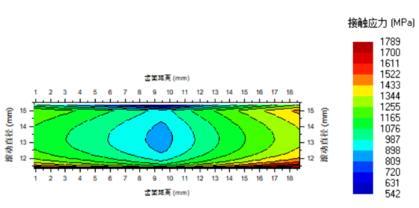
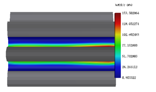
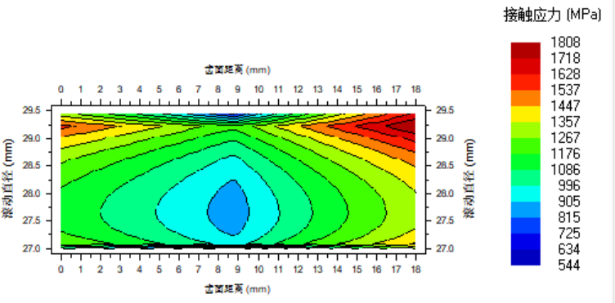
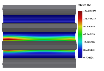
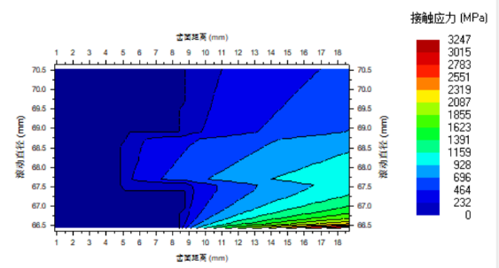
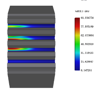
As shown in FIG. 6, under this working condition, the solar wheel, planetary wheel and inner gear ring of the secondary gear train are subjected to stress distribution of different degrees, and the solar gear tooth surface stress value is 1789MPa and the tooth root stress value is 153.50MPa. The surface stress of the planetary gear tooth is 1808MPa and the root stress is 130.24MPa. The surface stress of the inner gear ring is 3247MPa, and the root stress is 93.04MPa. The stress value of the sun wheel and the planet wheel of the secondary gear train is less than that of the primary gear train, but the stress value of the secondary inner gear ring is greater than that of the primary inner gear ring, because the secondary inner gear ring is connected with the secondary gear train, the secondary planetary frame needs to drive the output shaft to rotate, and there is a bearing fixed support on it. On the whole, the stress value of the secondary gear train is also within a reasonable range, and the overall structure of the reducer will not be damaged in a short time.
6. Summary
This paper mainly designs the steering gear reducer on the electric vehicle. Through the comprehensive analysis of the steering principle of the electric vehicle, the design of the reducer adopts the two-stage planetary gear transmission mode, and the gear is spur gear. The basic parameters of the design of the two-stage steering reducer are given by referring to the literature. At the same time, the paper calculates the transmission ratio and the number of gears of the reducer, and draws the corresponding three-dimensional model by using the three-dimensional software Solidworks. Finally, the strength and deformation of the two-stage planetary transmission gear reducer are checked and analyzed by using the finite element software ROMAX. The simulation results show that the design strength of the two-stage reducer meets the requirements, the overall structure deformation is small, the movement process will not affect the overall electric vehicle, and the structural design meets the requirements.
References
[1]. LIU Xiaosong, CHAO Yaqin. Research on Gear Design of Two-Stage Reducer for Pure Electric Vehicle [J]. Special Purpose Vehicle,2023(07):28-30.
[2]. Wang Shushan, Liu Hongguo, Yang Baocai. Research on Electric Vehicle Reducer Design Based on Fine and High Teeth [J]. Automotive Parts,2021(06):78-80.
[3]. Zhang Kaixuan, Zhou Zhikang, Hu Chenwei et al. Performance Optimization and Structure Design of Electric Vehicle Reducer [J]. Engineering & Test,2020,60(02):24-27+75.
[4]. Jie L ,Chongyang H ,Weibin W, et al.Load Spectrum Compilation Method of Hybrid Electric Vehicle Reducers Based on Multi-Criteria Decision Making [J]. Journal of Energies, 2022, (9) : 3293-3293.
[5]. Bo Z ,Wang X ,Liang L, et al.Influence of Lubricant Supply on Thermal and Efficient Performances of a Gear Reducer for Electric Vehicles[J].J. Tribol, 2021, 1-22.
[6]. Tian Junnan, Huang Rifan, Wang Yao et al. Research on Steering Stability of Steer-by-wire System of Electric Vehicle [J]. Times Automobile,2023(20):103-105.
[7]. Zhang Lingyan, Qiu Shuicai. Study on Modification Optimization of NGW Planetary Gear Transmission System [J]. Coal Mine Machinery,2023,44(08):123-127.
[8]. Rhoden Peak. A New Method for Transmission Ratio Distribution of Cylindrical Gear Reducer [J]. Journal of Mechanical Transmission,2013,37(05):108-109+122.
[9]. Feng Wei, Qiao Jinggan. Effect of Carburizing Temperature on Carburizing Layer of 20CrMnTi Gear Ring [J]. Hot Working Technology,2022,51(14):153-157.
[10]. Xie Zhongbing. Finite Element Analysis of Strength and Fatigue of Solar Wheel of Planetary Reducer [J]. Equipment Machinery,2023(02):74-77.
Cite this article
Man,X. (2024). Dynamic analysis of two-stage steering reducer for electric vehicle based on ROMAX. Theoretical and Natural Science,53,106-114.
Data availability
The datasets used and/or analyzed during the current study will be available from the authors upon reasonable request.
Disclaimer/Publisher's Note
The statements, opinions and data contained in all publications are solely those of the individual author(s) and contributor(s) and not of EWA Publishing and/or the editor(s). EWA Publishing and/or the editor(s) disclaim responsibility for any injury to people or property resulting from any ideas, methods, instructions or products referred to in the content.
About volume
Volume title: Proceedings of the 2nd International Conference on Applied Physics and Mathematical Modeling
© 2024 by the author(s). Licensee EWA Publishing, Oxford, UK. This article is an open access article distributed under the terms and
conditions of the Creative Commons Attribution (CC BY) license. Authors who
publish this series agree to the following terms:
1. Authors retain copyright and grant the series right of first publication with the work simultaneously licensed under a Creative Commons
Attribution License that allows others to share the work with an acknowledgment of the work's authorship and initial publication in this
series.
2. Authors are able to enter into separate, additional contractual arrangements for the non-exclusive distribution of the series's published
version of the work (e.g., post it to an institutional repository or publish it in a book), with an acknowledgment of its initial
publication in this series.
3. Authors are permitted and encouraged to post their work online (e.g., in institutional repositories or on their website) prior to and
during the submission process, as it can lead to productive exchanges, as well as earlier and greater citation of published work (See
Open access policy for details).
References
[1]. LIU Xiaosong, CHAO Yaqin. Research on Gear Design of Two-Stage Reducer for Pure Electric Vehicle [J]. Special Purpose Vehicle,2023(07):28-30.
[2]. Wang Shushan, Liu Hongguo, Yang Baocai. Research on Electric Vehicle Reducer Design Based on Fine and High Teeth [J]. Automotive Parts,2021(06):78-80.
[3]. Zhang Kaixuan, Zhou Zhikang, Hu Chenwei et al. Performance Optimization and Structure Design of Electric Vehicle Reducer [J]. Engineering & Test,2020,60(02):24-27+75.
[4]. Jie L ,Chongyang H ,Weibin W, et al.Load Spectrum Compilation Method of Hybrid Electric Vehicle Reducers Based on Multi-Criteria Decision Making [J]. Journal of Energies, 2022, (9) : 3293-3293.
[5]. Bo Z ,Wang X ,Liang L, et al.Influence of Lubricant Supply on Thermal and Efficient Performances of a Gear Reducer for Electric Vehicles[J].J. Tribol, 2021, 1-22.
[6]. Tian Junnan, Huang Rifan, Wang Yao et al. Research on Steering Stability of Steer-by-wire System of Electric Vehicle [J]. Times Automobile,2023(20):103-105.
[7]. Zhang Lingyan, Qiu Shuicai. Study on Modification Optimization of NGW Planetary Gear Transmission System [J]. Coal Mine Machinery,2023,44(08):123-127.
[8]. Rhoden Peak. A New Method for Transmission Ratio Distribution of Cylindrical Gear Reducer [J]. Journal of Mechanical Transmission,2013,37(05):108-109+122.
[9]. Feng Wei, Qiao Jinggan. Effect of Carburizing Temperature on Carburizing Layer of 20CrMnTi Gear Ring [J]. Hot Working Technology,2022,51(14):153-157.
[10]. Xie Zhongbing. Finite Element Analysis of Strength and Fatigue of Solar Wheel of Planetary Reducer [J]. Equipment Machinery,2023(02):74-77.