1. Introduction
WPT stands for wireless power transfer technology. WPT has numerous benefits over conventional power transfer techniques [1]: it eliminates the usage of wire, simply place and charge; it offers a wireless, all-brands charging solution for portable devices; it allows users to completely seal their electronic devices by removing the power port; it extends product life by preventing physical impacts with the power port; and it provides a broad charging power range
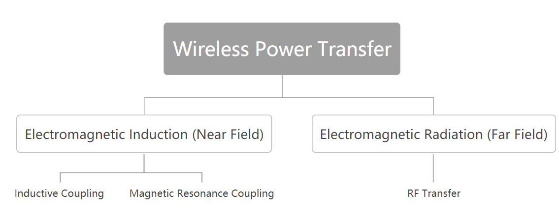
Based on their transmission distance, WPT technologies can be divided into two main groups: electromagnetic induction acting in the near field and electromagnetic radiation functioning in the far field [2]. An illustration of the categorization is provided. While far-field power transmission uses an effective transmission distance of several meters to several kilometers, far-field power transfer has a range of only a few milliliters to a few centimeters.
Following a brief introduction to WPT in part I, section II expands on the mechanisms of the most common WPT technologies before concluding the section with a comparison of the characteristics of various technologies. The three WPT applications are introduced in section III.
2. Wpt technologies
2.1. Magnetic Inductive Coupling
|
Figure 1. Classification of wireless power transfer technologies. |
Joseph Henry successfully constructed a telegraph of his own design in 1831 at a distance of 2.4 kilometers using the electromagnetic induction theories of British physicist Michael Faraday [3]. In 1888, German physicist Heinrich Hertz discovered the method of transmitting electricity without using wires across a very tiny air gap.
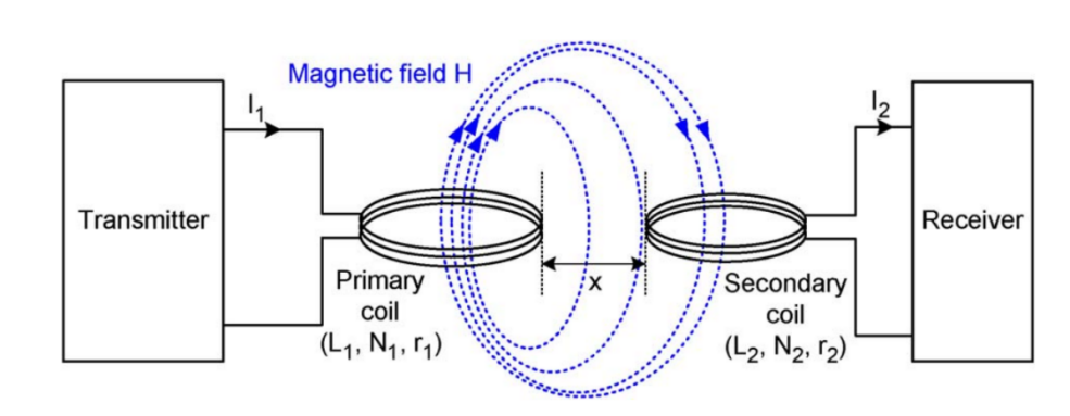
Through the use of electromagnetic induction, inductive coupling transmits electrical energy between two coils [4]. It uses a transmitter attached to a primary coil and a receiver coupled to a secondary coil, which shares the same principle as transformers. An alternating current is applied to the primary coil. In accordance with Faraday’s law of electromagnetic induction [5], the alternating current generates alternating magnetic flux which then transfers onto the secondary coil through an air gap. Magnetic flux linkage is defined as the product of the number of turns in a coil and the flux of the coil. However, the air gap is unable to function as a medium with high power transfer efficiency. As a result, the magnetic flux's intensity decreases quite quickly. Equation (1) provides corresponding magnetic flux density at x [6], where x is the separation between the primary coil and the secondary coil.
|
Figure 2. Magnetic inductive coupling [6]. |
\( Η(x)=\frac{{ΙΝr^{2}}}{2\sqrt[]{{({r^{2}}+{x^{2}})^{3}}}}\ \ \ (1) \)
The magnetic field intensity attenuates according to the cube of the reciprocal of the charging distance x. It is obvious that by improving the alternating current's amplitude I, the transmitting coil's number of turns N, and the coil's radius r will considerably increase the magnetic field's strength. Nevertheless, the coil's number of turns cannot be increased at will due to the size constraints of its implementation on portable devices. Equation (1) enables us to determine the ideal coil radius for the corresponding transmission range [7]. The effective charging distance of inductive coupling is typically within a few millimeters since the charging power attenuates quickly. The application of inductive coupling in the realm of RFID will be covered in part III. Passive RFID can operate up to 30 feet away, albeit at the cost of low power transmission efficiency. The power transfer efficiency and effective transfer distance should be balanced appropriately.
2.2. Magnetic Resonance Coupling
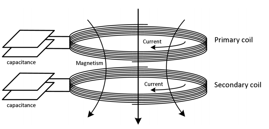
While both the transmitter and the receiver are adjusted to function at the resonant frequency, the mechanism of magnetic resonance coupling is quite similar to that of inductive coupling. Due to the strong coupling between the two coils, a greater effective distance can be achieved while maintaining a higher power transfer efficiency. This is accomplished by connecting capacitors in series with both coils. As depicted in Fig. 3, this is accomplished by connecting capacitors in series with both coils.
|
Figure 3. Magnetic resonance coupling. |
\( f=\frac{1}{2π\sqrt[]{LC}}\ \ \ (2) \)
The resonance frequency at which both coils are running is determined by equation (2). The power transfer is less likely to be impacted by the environment and other factors (eg. coil alignment) due to its resonance feature. Additionally, it has the ability to simultaneously charge several devices, which enables it to be used between a single transmitting resonator and numerous tuned receiving resonators that function at resonant frequency. If this is not calibrated appropriately, it could have certain negative effects. For instance, conflicts between various charging pathways.
|
Figure 4. Electromagnetic induction simplified circuit. |
Fig. 4 depicts the simplified circuit for electromagnetic induction power transfer, also known as near-field power transmission. The circuit is composed of an AC/DC rectifier, a DC/DC converter, a DC/AC inverter, a second AC/DC rectifier, and a third DC/DC converter [7]. Starting with an AC voltage, converted into a DC voltage through rectification. To ensure a decent transfer efficiency during air propagation, the DC source's voltage is raised using a DC/DC converter. After the energy is received by the secondary coil, it is re-rectified into DC voltage and tuned to the voltage required by the load.
Magnetic resonance coupling and magnetic inductive coupling operate at the same kilo-hertz rage frequency. In comparison to inductive coupling, the resonance feature also permits a greater effective power transmission distance. However, if an advanced LC circuit is used, more space will be needed since the charging of portable devices would be cumbersome.
2.3. RF Transfer
Radio-frequency transfer technology is categorized into far-field transfer. It is based on radio waves, a type of radiation that uses an entirely different medium. High frequency radio waves like X-rays and infrared rays are not commonly used because of safety concerns with electromagnetic wave exposure. Electromagnetic waves with frequencies between 300MHz and 300GHz are used in RF transmission [8].
\( {P_{R}}={P_{T}}\frac{{G_{T}}{G_{R}}{λ^{2}}}{{(4πd)^{2}}L}\ \ \ (3) \)
Formula (3) is known as the Harris transmission formula [9]. Where PR, PT, GT, GR, λ2, d and L represent the receiving power, the transmitted power, the gain of the receiver, the gain of the transmitter, the radio wavelength, the charging distance and the path loss factor respectively. The power received by the receiver attenuates according to the square of the reciprocal of the charging distance d, demonstrating that RF transfer loses power at a rate significantly slower than that of electromagnetic induction. Therefore, RF transfer that ranges from a few meters to a few kilometers has a greater effective power transfer distance. Keep in mind that in 1896, Nikola Tesla conducted an experiment in which he sent microwave signals over a distance of 48 kilometers [10]. The project provided Buffalo with AC voltage.
|
Figure 5. Radio-frequency transfer. |
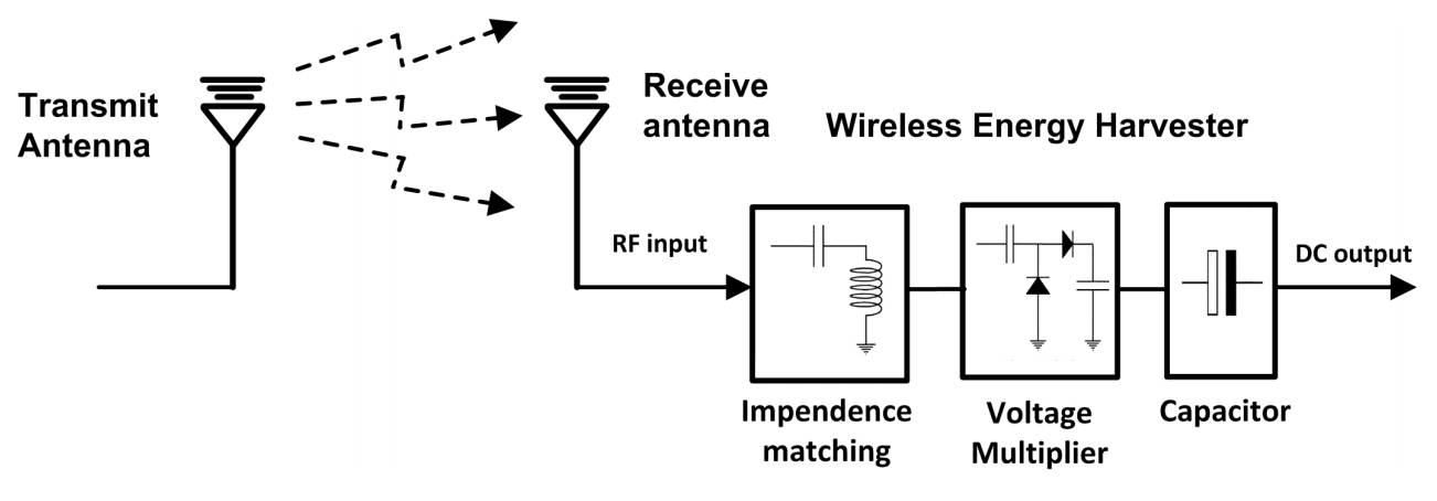
Fig. 5 displays the RF transfer circuit's structural layout. A rectifier is used to convert an AC power source into a DC power source, which is then converted to RF power at the end of the transmission. The radio wave is rectified into DC before being linked to the load after being transferred to the receiving antenna through the transmission antenna. The receiving antenna, impedance matching, and voltage multiplier are the four components that make up the RF energy harvesting method, which is heavily dependent on transfer efficiency. The impedance matching acts as a resonant circuit tuned at resonance frequency to increase the power transfer rate. To seamlessly convert RF signals to DC voltage, a capacitor and a voltage multiplier are connected in series. These two elements are crucial for both the effectiveness of the receiving antenna and RF transfer.
2.4. Summary on WPT technologies
We have outlined three WPT technologies in the three preceding subsections. This section will be devoted to comparing and summarizing these technologies. The pros and disadvantages of each WPT technology are outlined in Table I. In light of what has already been said, inductive and resonance coupling act in the near-field at kilohertz range, transferring from a few millimeters to a few meters distance. RF transmission uses radio waves as its medium and operates at megahertz to gigahertz frequencies in the far field. It has an effective charging range between a few meters and several kilometers.
Table 1. Comparison of different WPT technologies.
Field region | Propagation | Effective distance | Frequency | Advantage | Disadvantage | |
Inductive coupling | Near field | Electro- magnetic induction | From few milliliters To few centimeters | Kilo-Hertz range | ·Ease of implementation ·Safe for human | ·Short charging distance ·Heating effect ·Tight alignment required |
Magnetic resonance coupling | Near field | Electro- magnetic induction | From few Centimeters to Few meters | Kilo-Hertz range | ·High charging efficiency ·Loose alignment ·Multiple devices charging | ·Complex implementation ·Limited charging distance ·Heating effect |
RF transfer | Far field | Radio wave | From several Meters to several kilometers | 300MHz To 300GHz | ·Long effective charging distance | ·Unsafe high RF exposure ·Line-of-sight charging |
Inductive coupling is simple to use and convenient, but it has a short charging distance. Tight alignment is also necessary for high power transmission efficiency. Resonance coupling, however, permits a slack alignment between two coils. The heating effect is a serious drawback shared by both coupling techniques. Faraday's law of induction states that an induced electromotive force is generated in the coil when the magnetic flux is changing. When a conductor is placed between the two coils, a powerful current known as an eddy current is generated inside the conductor, creating a heating effect. As some energy diffuses away as thermal energy, the efficiency of power transfer is reduced. RF transfer has a long transmission range, but unsafe due to high RF exposure. Additionally, line-of-sight charging is required for RF transfer [11], which means the path between the transmitter and receiver cannot be obstructed.
3. Wpt applications
3.1. Wireless charging
The primary use of WPT, which focuses on charging gadgets like mobile phones and electric vehicles (EVs), might be considered wireless charging. Linking to what we have already discussed, wireless charging offers a convenient charging method and has the potential to increase the product's life span. As technology advances, more phones on the market are equipped with a wireless charging function at high efficiency. The application of WPT to EVs will also play an important role in the future. The pursuit of an environmentally friendly lifestyle by countries prompts the implementation of EV wireless charging technologies. More parking lots built specially for EVs will be seen, and more brands and companies will invest in EVs in the future. Yet, a number of issues must be resolved. such as a vehicle and transmitter misalignment that affects the effectiveness of the transmission.
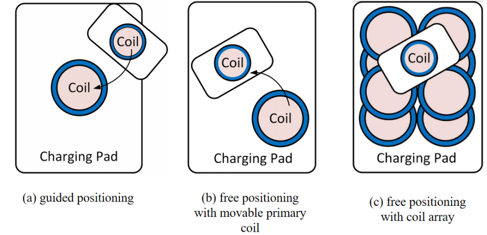
Organizations around the globe have been trying to unify the global wireless charging standardization. Few mainstream charging standards have been proposed and widely implemented. For instance, the Qi standard, A4WP standard, and PMA standard [12]. The following passage will focus on the Qi standard. The Qi standard (pronounced ‘Tchi’), created by Wireless Power Consortium (WPC) in 2008, is now regarded as the international wireless charging standard [13]. The Qi standard certified brands include Apple, Sony, LG, etc. Compatibility charging are guaranteed between these devices. The Qi standard adopts magnetic inductive coupling technology operating at frequencies from 105kHz to 205kHz with a maximum voltage of 200 volts. The guided positioning, free positioning with a single coil, and free positioning with a coil array are three wireless charging methodologies suggested.
|
Figure 6. Qi standard wireless charging approaches. |
Guided positioning (Fig. 6(a)) is a one-to-one fixed charging without any movable components. Inductive coupling between two coils is activated by simply placing the charging device on top of the gadget being charged. The smartphone and the charging pad's primary coil need to be in exact alignment for high efficiency charging to occur. By harnessing magnetic attraction, the Qi procedures ensure that the equipment is in a fixed position. Both the load and the charging pad contain a piece of magnet. Since the magnet is a conductor, eddy current will causes the magnetic field to be damped during air propagation, which will reduce the charging efficiency [14]. However, it is simple and practical to utilize this technique.
Free positioning using a locomotive primary coil (Fig.6(b)) is also one-to-one charging method but with a movable primary coil built underneath the charging pad, composed of a search device to locate the device and motors capavle of moving the primary coil on the x and y axis. The installation of the circuit underneath the charging pad does not require a large space. Both inductive and capacitive coupling methods can be used underneath the charging pad. The chassis structure and motors can be quite sophisticated and costly.
Free placement with a coil array (Fig. 6(c)) provides a mechanism for charging numerous devices at once. No matter where the charging device is placed or how it is positioned, many coils are built beneath the charging surface to provide free-positioning wireless charging. In comparison to previous alignment methods, this approach is more user-friendly, but at the cost of extremely difficult winding and tuning.
3.2. Passive/Active RFID
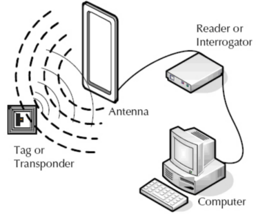
For decades, supply networks have used Radio Frequency Identification (RFID) to track and identify items. Combining time savings with automation, the ability to track assets, and inventory management results in better profits for businesses while still keeping low production costs. A simple RFID system is composed of a reader that connects to the computer and an RFID tag, or transponder. The information emitted by the transponders is received by specialized reader devices.
RFID can be classified into passive and active. Active RFID tags may be accessible from a greater distance since they have their own power source, whereas passive RFID tags must be powered by an external reader. The on-board battery of active RFID tags allows for a stronger signal to be emitted. It operates at a much higher frequency than passive RFID due to its characteristics, typically between 455MHz and 5.8GHz [15]. They are frequently used on large items and are also more expensive and larger in size. Only when the active tag is within a distance of 20 to 100 meters from the transponder can they engage with it.
|
Figure 7. Passive RFID [15]. |
Passive tags however, are more exquisite, cheap and small in size, and are commonly used on small items. The mechanism of passive RFID is illustrated in Fig. 7. The process is carried out as per below:
1. Tags come within the reader’s range
2. The reader emits an electromagnetic signal which the passive tags then receive through its antenna
3. Passive tags store the energy in an on-board capacitor
4. The on-board capacitor releases the energy to the tag’s coil through the process of inductive coupling
5. Passive tags release the encoded radio wave which the reader then demodulates
Passive RFID tags operate at a lower frequency, ranging from 128KHz to 915MHz and a relatively limited communication range from few inches to 30 feet.
Security and privacy are the two key issues with RFID technology. RFID tags can track and identify movement, which allows for the disclosure of user information. As customers enter the readers' detection range in shops, tags implanted in their clothing will be read to determine the moment of purchase or price information. The function of a "kill switch," which can be used to disable the tags, can be employed to solve the issue [16].
It is indisputable that RFID is a promising technology and we should not undervalue its potential in the areas of supply chain management and item tracking, despite a few concerns arising during the installation of the technology.
3.3. Medical implants
Medical implants are auxiliary devices inserted into the body or applied to its surface that act as prosthese to treat organ and tissue malfunctions [17]. If used intermittently, implants can be surgically removed. For those who use them permanently, installation is done through operations. Batteries are used in low-power devices like pacemakers and heart pumps; these batteries must be replaced and recharged surgically. The installation or removal of medical implants during surgical operations might be fatal. Additionally, surgical operations could have a severe impact on patients in the form of trauma, bleeding, infections, and anaesthetic issues. Therefore, it would be in their best interests to have surgery as minimally as possible.
As far as WPT technology is concerned, it can be applied to the wireless charging of medical implants, eliminating the need of surgical replacements. Near-field electromagnetic charging is commonly used. Due to the existence of transmission coils, devices can be bulky and costly. Scientists are currently looking for ways to decrease the cost and size of the coil while increasing the charging distance and efficiency.
|
Figure 8. Cochlear implants [18]. |
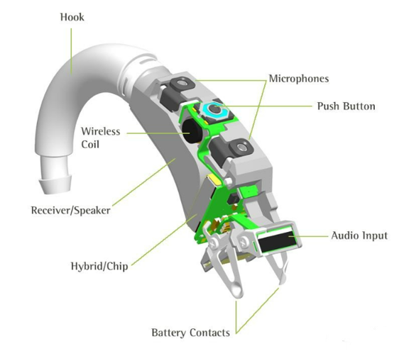
The cochlear implant [18], shown in Fig. 8. is a typical illustration of how WPT is used on medical implants. The external microphone and transmission system, as well as the receiver implanted in the inner ear, comprise the two primary parts of the cochlear implant. Through inductive connection, the external signal processing unit delivers energy to the implant [19]. Battery replacement for the external transmitting system is also possible using WPT. Unless the internal receiver is damaged, the implant operates as intended. At present, the global cochlea implants market has reached 1.5 billion dollars, yet it has improved the living standard of millions of people.
4. Conclusion
To conclude these transfer methodologies, inductive coupling and magnetic resonance coupling operating on the near field using electromagnetic induction possess a limited transfer range but are implemented widely on portable devices due to their simplicity, whilst RF transfer operating in the far field has a long effective power transmission range and can be implemented in large scale charging. WPT has considerably enhanced our technology over the last few decades and has introduced a number of innovative applications. We have provided a thorough analysis of wireless power transfer technologies in this paper. It begins with three prevailing transfer methods, and is followed by its applications.
While implementing this technology, there are still some challenges. Take gadget miniaturisation as an example. WPT circuits require a lot of room for their coils, transistors, resistors, and capacitors, especially when used in portable electronic devices. Additionally, the propagation duration may be impacted by the surroundings of the device, including the materials. As a result, technology ought to develop in the direction of a highly effective, inexpensive, and compact solution. These problems might be seen as goals and directions for future research and studies.
References
[1]. Admin. (2022). Wireless Power Transfer Circuit working, advantages and disadvantages. WatElectronics.com. Retrieved September 19, 2022, from https://www.watelectronics.com/wireless-power-transfer/
[2]. Ching, T. W., & Wong, Y. S. (2013). Review of wireless charging technologies for electric vehicles. In 2013 5th International Conference on Power Electronics Systems and Applications (PESA) (pp. 1-4). IEEE.
[3]. Williams, L. P. (1999). Michael Faraday. Encyclopædia Britannica. Retrieved September 19, 2022, from https://www.britannica.com/biography/Michael-Faraday
[4]. Ho, S. L., Wang, J., Fu, W. N., & Sun, M. (2011). A comparative study between novel witricity and traditional inductive magnetic coupling in wireless charging. IEEE Transactions on Magnetics, 47(5), 1522-1525.
[5]. Electrical4U. (2021). Faraday's laws of electromagnetic induction: First & second law. Electrical4U. Retrieved September 19, 2022, from https://www.electrical4u.com/faraday-law-of-electromagnetic-induction/
[6]. Mayordomo, I., Dräger, T., Spies, P., Bernhard, J., & Pflaum, A. (2013). An overview of technical challenges and advances of inductive wireless power transmission. Proceedings of the IEEE, 101(6), 1302-1311.
[7]. Finkenzeller, K. (2008). Fundamentals and applications in contactless smart cards, radio frequency identification and near-field communication. wiley.
[8]. Lu, X., Wang, P., Niyato, D., Kim, D. I., & Han, Z. (2014). Wireless networks with RF energy harvesting: A contemporary survey. IEEE Communications Surveys & Tutorials, 17(2), 757-789.
[9]. Balanis, C. A. (2015). Antenna theory: analysis and design. John wiley & sons.
[10]. Hunt, I. W. (1999). Nikola Tesla. Encyclopædia Britannica. Retrieved September 19, 2022, from https://www.britannica.com/biography/Nikola-Tesla
[11]. Krikidis, I., Timotheou, S., & Sasaki, S. (2012). RF energy transfer for cooperative networks: Data relaying or energy harvesting?. IEEE Communications letters, 16(11), 1772-1775.
[12]. Powermatters.org ▷ powermatters. HypeStat. (n.d.). Retrieved September 19, 2022, from https://hypestat.com/info/powermatters.org
[13]. Hui, S. Y. (2013). Planar wireless charging technology for portable electronic products and Qi. Proceedings of the IEEE, 101(6), 1290-1301.
[14]. Zhong, W. X., Liu, X., & Hui, S. R. (2010). A novel single-layer winding array and receiver coil structure for contactless battery charging systems with free-positioning and localized charging features. IEEE Transactions on Industrial Electronics, 58(9), 4136-4144.
[15]. Weinstein, R. (2005). RFID: a technical overview and its application to the enterprise. IT professional, 7(3), 27-33.
[16]. Juels, A. (2006). RFID security and privacy: A research survey. IEEE journal on selected areas in communications, 24(2), 381-394.
[17]. Fan, X., Shangguan, L., Howard, R., Zhang, Y., Peng, Y., Xiong, J., ... & Li, X. Y. (2020). Towards flexible wireless charging for medical implants using distributed antenna system. In Proceedings of the 26th annual international conference on mobile computing and networking (pp. 1-15).
[18]. U.S. Department of Health and Human Services. (2021). Cochlear implants. National Institute of Deafness and Other Communication Disorders. Retrieved September 19, 2022, from https://www.nidcd.nih.gov/health/cochlear-implants
[19]. Lu, X., Wang, P., Niyato, D., Kim, D. I., & Han, Z. (2015). Wireless charging technologies: Fundamentals, standards, and network applications. IEEE communications surveys & tutorials, 18(2), 1413-1452.
Cite this article
Song,Y. (2023). An Overview of Technologies and Applications of Wireless Power Transfer. Theoretical and Natural Science,5,315-323.
Data availability
The datasets used and/or analyzed during the current study will be available from the authors upon reasonable request.
Disclaimer/Publisher's Note
The statements, opinions and data contained in all publications are solely those of the individual author(s) and contributor(s) and not of EWA Publishing and/or the editor(s). EWA Publishing and/or the editor(s) disclaim responsibility for any injury to people or property resulting from any ideas, methods, instructions or products referred to in the content.
About volume
Volume title: Proceedings of the 2nd International Conference on Computing Innovation and Applied Physics (CONF-CIAP 2023)
© 2024 by the author(s). Licensee EWA Publishing, Oxford, UK. This article is an open access article distributed under the terms and
conditions of the Creative Commons Attribution (CC BY) license. Authors who
publish this series agree to the following terms:
1. Authors retain copyright and grant the series right of first publication with the work simultaneously licensed under a Creative Commons
Attribution License that allows others to share the work with an acknowledgment of the work's authorship and initial publication in this
series.
2. Authors are able to enter into separate, additional contractual arrangements for the non-exclusive distribution of the series's published
version of the work (e.g., post it to an institutional repository or publish it in a book), with an acknowledgment of its initial
publication in this series.
3. Authors are permitted and encouraged to post their work online (e.g., in institutional repositories or on their website) prior to and
during the submission process, as it can lead to productive exchanges, as well as earlier and greater citation of published work (See
Open access policy for details).
References
[1]. Admin. (2022). Wireless Power Transfer Circuit working, advantages and disadvantages. WatElectronics.com. Retrieved September 19, 2022, from https://www.watelectronics.com/wireless-power-transfer/
[2]. Ching, T. W., & Wong, Y. S. (2013). Review of wireless charging technologies for electric vehicles. In 2013 5th International Conference on Power Electronics Systems and Applications (PESA) (pp. 1-4). IEEE.
[3]. Williams, L. P. (1999). Michael Faraday. Encyclopædia Britannica. Retrieved September 19, 2022, from https://www.britannica.com/biography/Michael-Faraday
[4]. Ho, S. L., Wang, J., Fu, W. N., & Sun, M. (2011). A comparative study between novel witricity and traditional inductive magnetic coupling in wireless charging. IEEE Transactions on Magnetics, 47(5), 1522-1525.
[5]. Electrical4U. (2021). Faraday's laws of electromagnetic induction: First & second law. Electrical4U. Retrieved September 19, 2022, from https://www.electrical4u.com/faraday-law-of-electromagnetic-induction/
[6]. Mayordomo, I., Dräger, T., Spies, P., Bernhard, J., & Pflaum, A. (2013). An overview of technical challenges and advances of inductive wireless power transmission. Proceedings of the IEEE, 101(6), 1302-1311.
[7]. Finkenzeller, K. (2008). Fundamentals and applications in contactless smart cards, radio frequency identification and near-field communication. wiley.
[8]. Lu, X., Wang, P., Niyato, D., Kim, D. I., & Han, Z. (2014). Wireless networks with RF energy harvesting: A contemporary survey. IEEE Communications Surveys & Tutorials, 17(2), 757-789.
[9]. Balanis, C. A. (2015). Antenna theory: analysis and design. John wiley & sons.
[10]. Hunt, I. W. (1999). Nikola Tesla. Encyclopædia Britannica. Retrieved September 19, 2022, from https://www.britannica.com/biography/Nikola-Tesla
[11]. Krikidis, I., Timotheou, S., & Sasaki, S. (2012). RF energy transfer for cooperative networks: Data relaying or energy harvesting?. IEEE Communications letters, 16(11), 1772-1775.
[12]. Powermatters.org ▷ powermatters. HypeStat. (n.d.). Retrieved September 19, 2022, from https://hypestat.com/info/powermatters.org
[13]. Hui, S. Y. (2013). Planar wireless charging technology for portable electronic products and Qi. Proceedings of the IEEE, 101(6), 1290-1301.
[14]. Zhong, W. X., Liu, X., & Hui, S. R. (2010). A novel single-layer winding array and receiver coil structure for contactless battery charging systems with free-positioning and localized charging features. IEEE Transactions on Industrial Electronics, 58(9), 4136-4144.
[15]. Weinstein, R. (2005). RFID: a technical overview and its application to the enterprise. IT professional, 7(3), 27-33.
[16]. Juels, A. (2006). RFID security and privacy: A research survey. IEEE journal on selected areas in communications, 24(2), 381-394.
[17]. Fan, X., Shangguan, L., Howard, R., Zhang, Y., Peng, Y., Xiong, J., ... & Li, X. Y. (2020). Towards flexible wireless charging for medical implants using distributed antenna system. In Proceedings of the 26th annual international conference on mobile computing and networking (pp. 1-15).
[18]. U.S. Department of Health and Human Services. (2021). Cochlear implants. National Institute of Deafness and Other Communication Disorders. Retrieved September 19, 2022, from https://www.nidcd.nih.gov/health/cochlear-implants
[19]. Lu, X., Wang, P., Niyato, D., Kim, D. I., & Han, Z. (2015). Wireless charging technologies: Fundamentals, standards, and network applications. IEEE communications surveys & tutorials, 18(2), 1413-1452.


