


Electromagnetic Railgun (EMRG), Synchronous Induction Coilgun (SiCG), Electromagnetic force, Biot-Savart Law, Hall switch.
1. Introduction
The electromagnetic railgun represents a major advancement in projectile acceleration technology. It uses electromagnetic principles to launch projectiles at very high speeds. Unlike traditional cannons and artillery that rely on chemical propellants, the railgun uses electromagnetic forces to achieve superior speed, range, and impact performance.
The idea of using electromagnetic forces for propulsion dates back to the early 20th century. In the 1920s, French inventor Louis Octave Fauchon-Villeplee's pioneering work laid the foundation for modern railgun technology. [5]His experiments proved the feasibility of accelerating projectiles with electromagnetic force, though practical application was limited by the technology of the time.
Significant progress was made in the latter half of the 20th century, especially during the 1980s and 1990s, driven by military research programs in the United States and other countries. Advances in power electronics, materials science, and computational modeling made the development of more efficient and powerful railgun systems possible. Today, research and development efforts continue to focus on overcoming technical challenges and enhancing the operational capabilities of electromagnetic railguns.
Key advantages of electromagnetic railguns include theoretically unlimited initial velocities, low operational costs, and safe storage and usage, making them crucial in military applications. As a cutting-edge weapon, electromagnetic railguns offer numerous advantages. Unlike traditional artillery that relies on chemical propellants, railguns use strong electrical pulses to generate Lorentz force, accelerating the projectile to extremely high speeds and reducing overall costs. Additionally, the high initial velocity of the projectile, railguns can achieve a maximum range of up to 100 kilometers, penetrating 80mm thick steel plates and three layers of concrete walls.
The internal structure of railguns is stable, and the projectile experiences a high and constant acceleration, leading to precise targeting. During the process of generating magnetic fields through strong electrical pulses, railguns are extremely quiet, making them difficult for enemies to detect and providing high levels of stealth and counter-reconnaissance capability.
Railgun technology has also been applied in other fields. For example, Chinese researchers have used railgun technology for forest firefighting, turning it into a long-range firefighting tool. By deploying unpowered fire extinguishing bombs over long distances, it effectively controls fires in forests and grasslands, thereby enhancing firefighter safety.
2. Theoretical basis
Figure 1: Principles and Construction of an Electromagnetic Railgun(picture from [14]website )
Figure 2: The design circuit of an electromagnetic railgun.
Figure 3: The design circuit of an electromagnetic railgun.
The theoretical bases of railgun are based on Ampere force, which is illustrated in Figure 1, Figure 2 and Figure 3. It mainly consists of a pair of parallel rails with a movable armature and components like a power source and a switch in between. When the switch is closed, a strong current is introduced into one rail[11]. Flows through the armature, and returns along the other rail. The current in the rails generates a magnetic field, which exerts a Lorentz force on the current-carrying armature, accelerating it and ejecting the projectile.
Before proceeding to the theoretical derivation, we need to understand what the inductance gradient is. Inductance gradient is an important concept in electromagnetism, which is used to describe the rate of change of inductance[11]. In simple terms, it is the ratio of the change in inductance to the change distance. To be specific is Derivative of inductance with respect to length. Inductance gradient is widely used in electromagnetics. It can be used to analyze inductance changes in circuits, predict current changes, and even be used to design various electronic devices. It's represented by the letter i.
From the above analysis, the author draws several conclusions. Firstly, the electromagnetic force depends on the inductance gradient, as well as the current strength. Proportional to the inductance gradient, proportional to the square of the current. Secondly, there are no two inductance gradients, and the inductance gradient used to calculate the electromagnetic force is the increase rate of inductance.
First you need to find the size of the magnetic field, which uses Biot Savart's law:
Figure 4: An analysis of magnetic field on one point
\( B=\int dB=\int \frac{{μ_{0}}I}{4π}\frac{dl}{{a^{2}}}sin{θ} \) (1)
So we can get:
\( B=\frac{{μ_{0}}I}{4πa}(cos{{θ_{1}}}-cos{{θ_{2}}}) \) (2)
If \( {θ_{1}}=0 \) \( {θ_{2}}=∞ \)
\( B=\frac{{μ_{0}}I}{2πa} \) (3)
Because there's a joint magnetic field between the two wires, so the Magnetic flux is:
\( {∅_{B}}=\iint B∙dA \) (4)
\( {∅_{B}}=\frac{x{μ_{0}}I}{π}ln{(\frac{R+L}{R})} \) (5)
X is part length of rail (m)
Self-induced-e.m.f:
\( E=L\frac{dI}{dt} \) (6)
\( E=\frac{x{μ_{0}}dI}{πdt}ln{(\frac{R+L}{R})} \) (7)
Induce gradient:
\( \frac{L}{x}=\frac{{μ_{0}}}{π}ln{(\frac{R+L}{R})} \) (8)
Ampere-force:
\( F=BIL=\frac{{μ_{0}}{I^{2}}}{4π}\int _{R}^{R+L}\frac{da}{a}=\frac{{μ_{0}}{I^{2}}}{2π}ln{(\frac{R+L}{R})} \) (9)
This means that all we need to do is calculate the inductance gradient, the current, and we can get the force on the railgun bullet
Therefore, the force on the armature can also be expressed as:
\( F=\frac{i{I^{2}}}{2} \) (10)
where F is the Lorentz force (N), i is the inductance gradient of the rails (H/m), and I is the current intensity (A). B is Magnetic field size(T), \( μ \) is the vacuum permeability R is radius of rail(m). L is distance between two rails
(suppose we do not consider L \( ≫R \) )
The acceleration of the projectile is:
\( a=\frac{F}{m}=\frac{i{I^{2}}}{2m} \) (11)
where m is the mass (kg). From equation (2), it is evident that the greater the current intensity in the rails, the greater the acceleration of the projectile and the faster its velocity.
Railguns can have various structural forms such as single, series, parallel, and multi-layer configurations. Depending on the rail structure, the muzzle cross-section can be square, circular, or elliptical. Armatures can be made of solid metal, plasma, or ahybrid type. Power sources providing pulsed power include capacitor banks, high-performance batteries, various types of homopolar generators, pulse transformers, compulsators, and explosive generators, as well as planned superconducting energy storage systems.
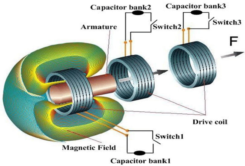
Figure 5: Principles and Construction of an Electromagnetic Coilgun (picture from [15]website)
The theoretic bases of a coilgun is based on the Lorentz force ,which is illustrated in Figure 4&5. It mainly consists of a fixed coil, a metal or magnet, an energy storage device, and a switch. The fixed coil acts as the barrel, and the movable coil acts as the projectile. When the fixed coil is connected to a power source, the magnetic field generated interacts with the induced current in the movable coil, producing a Lorentz force that accelerates the projectile coil and ejects it. The force on the projectile can be expressed as:
\( F={I_{f}}∙{I_{p}}∙\frac{dM}{dx} \) (12)
where F is the Lorentz force (N), f is the current intensity in the fixed coil (A), p is the current intensity in the projectile coil (A), M is the mutual inductance between the fixed and movable coils (H), and d is the mutual inductance gradient (H/m). From equation (3), it can be seen that the greater the current intensity in the fixed coil, the greater the induced current intensity in the projectile coil, and the greater the electromagnetic force on the projectile[13]
However, for our coil fabrication and research, we did not use a mutual inductance type of coil gun, so we used the force of a permanent magnet on each electromagnetic field of the coil. So the formulas and principles are going to be different.
The magnitude of the magnetic field in the ampere-ring can be obtained as:
\( \oint B∙dl=N∙{μ_{0}}∙I \) (13)
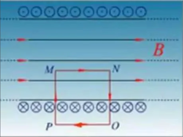
Figure 6: A Internal structure of solenoid
According to the picture, the external PO section of the magnetic field is zero due to its far distance, and the vector Angle between the magnetic field and the length of the NO and MP sections is 90 degrees, so the magnetic field is also zero. You can know it through the internal PO section:
\( \oint B∙dl=\int _{M}^{N}B∙dl+\int _{N}^{O}B∙dl+\int _{O}^{P}B∙dl+\int _{P}^{M}B∙dl \)
\( =\int _{M}^{N}B∙dl=B∙MN={μ_{0}}∙MN∙nI \)
\( B={μ_{0}}∙nI \) (14)
Therefore, the magnetic field of the permanent magnet inside the solenoid is constant
Where B is the magnetic field size (T), n is the number of coils, n is the number of coils per unit length (N/m), and I is the current size (A).
The force exerted on magnet:
\( {F_{B}}=m∙x∙v∙B∙\frac{dB}{dl} \) (15)
Where F is magnetic force(N),m is the mass of magnet(kg), v is the volume of magnet( \( {m^{3}}) \) , \( \frac{dB}{dx} \) is the magnetic gradient (T/m),x is the Specific magnetization coefficient of magnet( \( \frac{k}{ρ} \) , where k is the volume susceptibility)
However, the use of this formula is too troublesome and not easy to understand, so an alternative method is given. It is solved by conservation of energy:
\( {F_{B}}∙l=\frac{1C{U^{2}}}{2} \) (16)
Where C is value of capacitance(F) and V is the potential difference after the capacitor is fully charged(V)
3. Method
The author Plans the basic circuit and draw initial schematics. The track is modeled in 3D as shown in figure 8 and 9.( We choose to use FreeCAD to make a 3D model)

Figure 7: 3D modeling software on the track connecting part of the model

Figure 8: Track model on 3D modeling software
Secondly, obtain procure materials Including DC Power system, Wire, Pipe , Magnet, Switch, and Capacitor. The brass rial is customized for printing. Thirdly, decide to wrap up all the coil on the pipe. And then Simulation and commissioning: Conduct initial tests with low power to simulate the system and ensure all components are functioning correctly.
The following process is optimization: Analyze collected data to identify inefficiencies and failure points. Finally, adjustment: (Adjust rail alignment, projectile design, and power settings as needed to optimize performance)
However, the switch is the biggest problem and most need to be improved in this coil processing, Because the Hall switch is not considered, but through a simple fuse to achieve the purpose of emission, the final magnet emission speed is always less than the ideal speed. Because simple manual fusing can not accurately control the discharge time of the capacitor, that is, there is an energy error caused by too much or too little discharge.
If the Hall switch is used, then the situation is different.
1. Principle of Hall switch: When a sheet of metal or semiconductor with an electric current is placed vertically in a magnetic field, the two ends of the sheet produce a potential difference, which is called the Hall effect.
The input of Hall switch is characterized by the magnetic induction intensity B. When the value of B reaches a certain degree (such as B1), the trigger inside Hall switch flips, and the output level state of Hall switch flips accordingly.
Based on this theory, if the Hall switch is placed next to the solenoid, according to the Lenz law in the inductance, the Hall switch will clearly detect the change in the magnetic field during the discharge of the capacitor. Therefore, the Hall switch can achieve a more accurate fuse timing than the manual fuse
4. Challenges in practical application:
4.1. Volume and Weight Disparities
Currently, the muzzle energy of tank guns and self-propelled artillery can reach 4-10 MJ, with the artillery's volume being between 1-3 cubic meters and weighing 2-4 tons. In contrast, an electromagnetic gun with similar firing capabilities has a pulse power source volume of 15-30 cubic meters and weighs 15-20 tons, which is 5-10 times more than conventional artillery. Tanks and self-propelled artillery do not have the space or load capacity to accommodate this. For example, a submachine gun only requires 2-5 kg.[4]An electromagnetic gun with the same capability weighs at least 20 kg, making it impractical for a soldier to carry over long distances. While warships have enough space, missiles have already taken precedence, rendering artillery largely obsolete on ships.
4.2. Cost Inefficiency and Structural Limitations
Coilguns and heavy artillery have barrel lengths that are too long to be mounted on tanks or vehicles, and even warships cannot accommodate them.
Even if electromagnetic guns were mass-produced, their cost would be over five times higher than that of conventional artillery with similar capabilities, making electromagnetic guns uncompetitive.
Structural Limitations
Coilguns and heavy artillery have barrel lengths that are too long to be mounted on tanks or vehicles, and even warships cannot accommodate them.
4.3. Durability and Longevity
The only electromagnetic gun with significant firing capabilities is the railgun. However, due to high-speed shaving and ablation issues, the lifespan of the rails is difficult to exceed 100 rounds, whereas the lifespan of conventional artillery is 1000-3000 rounds, and ordinary gun barrels can even reach up to 100,000 rounds. On the battlefield, a near-miss can cause the rails to bend slightly, rendering them unable to conduct electricity and therefore unable to fire, necessitating replacement.
4.4. Accuracy Issues
Conventional artillery can have rifling engraved inside the barrel, causing the projectile to spin during flight, which significantly enhances accuracy. Railguns, however, cannot have rifling engraved, resulting in poorer accuracy. Even if projectiles use tail fins to reduce dispersion, they still fall short of the accuracy of spinning projectiles and have higher wind resistance. Other electromagnetic guns also find it challenging to engrave rifling, and their muzzle energy is much lower.
4.5. Vulnerability to Damage
The main components of electromagnetic guns are almost entirely precision electronic parts, which are easily incapacitated by attacks, offering almost no resistance to damage. For instance, conventional artillery is made of high-strength steel, and if an enemy shell lands 10 meters away, it might only damage a few small parts, which can be replaced quickly to continue fighting. Electromagnetic guns, however, consist of delicate capacitors and other electronic equipment, with capacitor layers as thin as 0.01 mm, which can be easily pierced by shockwaves from shells. A 100 kg capacitor can be rendered useless if even a small piece of shrapnel pierces it. If a shell lands within 10 meters of an electromagnetic gun, it is likely to be entirely destroyed, eliminating the need for repair.[4]
4.6. Energy Efficiency and Power Requirements
Conventional artillery can fire continuously at a rate of 5-10 rounds per minute. Electromagnetic guns typically have an overall energy efficiency of less than 30%, necessitating a power generation capacity of 2000-4000 kW for an electromagnetic gun with similar capabilities. This is equivalent to the power of 2-4 tanks or 0.5-1.5 locomotives. Therefore, a self-propelled artillery equipped with an electromagnetic gun would require an additional high-power generator vehicle, significantly increasing the burden on personnel and equipment, and making it easier to destroy.
4.7. Diminished Role of Artillery
In modern warfare, missiles dominate, and the role of artillery is diminishing. Compared to missiles, artillery shells have several critical disadvantages. First, because artillery shells need to withstand tens of thousands of Gs of acceleration during firing, their structural strength must be very high, making the shells almost entirely steel with a charge ratio generally below 8%, resulting in minimal explosive power[8] Research and design of simulated electromagnetic crankshot device. Marine Electronics Engineering ). Second, missiles can be equipped with various guidance devices to adapt to different targets, making them highly versatile and accurate. In contrast, even guided artillery shells have limited use and adaptability, and unguided shells are akin to blindly throwing stones in modern warfare. Third, a missile with equivalent destructive power would weigh about 10 tons, whereas artillery shells, due to their low hit rate, would require over 100 tons, and the artillery to launch these shells would weigh over 500 tons. If using electromagnetic guns, this would increase to over 3000 tons. The heavy artillery shells and launch equipment make them highly visible and easy targets for the enemy.
Given these points, the role of conventional artillery is already diminishing, making electromagnetic guns even less valuable.
4.8. Air Resistance and Range Limitations
Air resistance is proportional to the square of the speed, so range does not increase proportionally with the square of the initial velocity, but rather with the 1.3-1.5 power of the initial velocity. Thus, while the muzzle velocity of electromagnetic guns could potentially be much higher than that of conventional artillery, the increased air resistance due to high initial velocity results in only a modest increase in range. Conversely, the cost of increasing the initial velocity for electromagnetic guns is proportional to the square of the velocity. In contrast, missiles can be equipped with glide wings, allowing them to glide for hundreds of kilometers, a range unattainable by any artillery shell.
In summary, electromagnetic guns are highly inefficient in terms of personnel and equipment on the battlefield. Given the same cost, combat weight, and personnel allocation, the capability of electromagnetic guns to fire projectiles is less than one-fifth that of conventional artillery, with survivability less than one-tenth. Electromagnetic guns may find limited use in some niche combat scenarios but cannot be widely deployed and certainly cannot replace aircraft and missiles to become the mainstay of future battlefields.
Finally, although the moment of practical application of the electromagnetic gun has not yet arrived, but with various technical obstacles have been overcome, I believe that one day, we will see its style on the battlefield.
5. Conclusion
The production and theoretical research of electromagnetic guns are divided into coil guns and rail guns, and the derivation of the two types is essentially based on the Biot-Savat law. For the railgun, the magnetic field force acting on the electromagnet is obtained by deducing the inductance gradient of the electromagnetic track. At the same time, 3D modeling and printing were used to obtain a physical model of the railgun. For the coil gun, the Ampere circulation theorem can also be obtained from the Biot-Savat law, so as to obtain a constant magnetic field size and find the force of the permanent magnet. At the technical level, the production cost of the coil gun is much lower than that of the rail gun, the main component of the coil gun is copper wire, the price is far lower than 3D printing, and the production time and operation safety are better than the rail gun. A critical limitation of this study was the absence of motion sensors, which could have provided valuable data on projectile speed. This article hopes to bring readers the properties of the orbital electromagnetic gun and the coil electromagnetic gun to provide a quantitative theoretical basis.
References
[1]. Ranabhat, K., Patrikeev, L., Antal'evna, R. A., Andrianov, K., Lapshinsky, V., & Sofronova, E. (2016). An introduction to solar cell technology. Journal of Applied Engineering Science, 14(4), 481-491.
[2]. Blakers, A., Zin, N., McIntosh, K. R. & Fong, K. (2013). High efficiency silicon solar cells. Energy Procedia, 33, 1-10.
[3]. Liang Wei Shan Xie Youhui & Wang Yibo.(2023). Research and design of small analog electromagnetic gun. Technology and innovation (08), 4.14-16. Doi: 10.15913 / j.carol carroll nki kjycx. 2023.08.004.
[4]. Zhou Zhuangqi Zheng Shangchao Yu Jun (2012) Analysis of electromagnetic gun technology
[5]. Guo Yanxi Han Tao Zeng Zhipeng Ma Yingnan, Jiang Chunzhi & Tang Zhenghua.(2023). Working principle and finite element simulation analysis of electromagnetic gun. Laboratory research and exploration (02) 120-122 + 164. The doi: 10.19927 / j.carol carroll nki syyt. 2023.02.025.
[6]. Liu Wenhao Gao Chuanzhi & Xie Wei.(2021). Design and implementation of electromagnetic curving gun experimental device. Computer measurement and control (09), 137-141 + 146. Doi: 10.16526 / j.carol carroll nki. 11-4762 / tp. 2021.09.026.
[7]. You Liping.(2021). Design of simulated electromagnetic curving gun. Electronic test (12), 5-7 + 71. Doi: 10.16520 / j.carol carroll nki. 1000-8519.2021.12.001.
[8]. Chen Xin-Xi Wei Li-Jun & ZHANG Wen-Chu.(2020). Research and design of simulated electromagnetic crankshot device. Marine Electronics Engineering (08),173-177.
[9]. Ma Yan-E Cheng Ze-Lin & Zheng Yang-Fan.(2021). System design for simulating electromagnetic curving gun. Changjiang Information and Communication (09),47-48+51.
[10]. Huang Jianlin CAI Zhiyuan & Yin Jinshan.(2021). Design of intelligent simulation electromagnetic gun control system. Electronic world (05), 182-183. The doi: 10.19353 / j.carol carroll nki DZSJ. 2021.05.077
[11]. Liu yan peng Yang li-jia Ou Yangjianming(2009).Two representations and equivalence of the force on coil projectile1000—0712(2009)09-0019—03
[12]. Peng Zhiran Wang Guangsen Zhai Xiaofei Zhang Xiao(2019) time-varying inductance gradient modeling and analysis of electromagnetic orbital launcher
[13]. Zhang Chao-wei, LI Zhi-Yuan, Chen Huo-yu 2005 armature force analysis of induction coil gun.
[14]. Blue Ocean Evergreen Think Tank (2019)The development of electromagnetic Rail guns in the United States https://www.163.com/dy/article/ESJH12880511DV4H.html
[15]. The Frozen Dragon (Bilibili users) (2021)The development and difficulties of electromagnetic drive projectile weapon https://www.bilibili.com/read/cv9108227/
Cite this article
Ma,M. (2025). Electromagnetic Railguns and Coil Guns: Comprehensive Analysis of Physical Principles and Applications and Experimental Improvements. Theoretical and Natural Science,87,15-25.
Data availability
The datasets used and/or analyzed during the current study will be available from the authors upon reasonable request.
Disclaimer/Publisher's Note
The statements, opinions and data contained in all publications are solely those of the individual author(s) and contributor(s) and not of EWA Publishing and/or the editor(s). EWA Publishing and/or the editor(s) disclaim responsibility for any injury to people or property resulting from any ideas, methods, instructions or products referred to in the content.
About volume
Volume title: Proceedings of the 4th International Conference on Computing Innovation and Applied Physics
© 2024 by the author(s). Licensee EWA Publishing, Oxford, UK. This article is an open access article distributed under the terms and
conditions of the Creative Commons Attribution (CC BY) license. Authors who
publish this series agree to the following terms:
1. Authors retain copyright and grant the series right of first publication with the work simultaneously licensed under a Creative Commons
Attribution License that allows others to share the work with an acknowledgment of the work's authorship and initial publication in this
series.
2. Authors are able to enter into separate, additional contractual arrangements for the non-exclusive distribution of the series's published
version of the work (e.g., post it to an institutional repository or publish it in a book), with an acknowledgment of its initial
publication in this series.
3. Authors are permitted and encouraged to post their work online (e.g., in institutional repositories or on their website) prior to and
during the submission process, as it can lead to productive exchanges, as well as earlier and greater citation of published work (See
Open access policy for details).
References
[1]. Ranabhat, K., Patrikeev, L., Antal'evna, R. A., Andrianov, K., Lapshinsky, V., & Sofronova, E. (2016). An introduction to solar cell technology. Journal of Applied Engineering Science, 14(4), 481-491.
[2]. Blakers, A., Zin, N., McIntosh, K. R. & Fong, K. (2013). High efficiency silicon solar cells. Energy Procedia, 33, 1-10.
[3]. Liang Wei Shan Xie Youhui & Wang Yibo.(2023). Research and design of small analog electromagnetic gun. Technology and innovation (08), 4.14-16. Doi: 10.15913 / j.carol carroll nki kjycx. 2023.08.004.
[4]. Zhou Zhuangqi Zheng Shangchao Yu Jun (2012) Analysis of electromagnetic gun technology
[5]. Guo Yanxi Han Tao Zeng Zhipeng Ma Yingnan, Jiang Chunzhi & Tang Zhenghua.(2023). Working principle and finite element simulation analysis of electromagnetic gun. Laboratory research and exploration (02) 120-122 + 164. The doi: 10.19927 / j.carol carroll nki syyt. 2023.02.025.
[6]. Liu Wenhao Gao Chuanzhi & Xie Wei.(2021). Design and implementation of electromagnetic curving gun experimental device. Computer measurement and control (09), 137-141 + 146. Doi: 10.16526 / j.carol carroll nki. 11-4762 / tp. 2021.09.026.
[7]. You Liping.(2021). Design of simulated electromagnetic curving gun. Electronic test (12), 5-7 + 71. Doi: 10.16520 / j.carol carroll nki. 1000-8519.2021.12.001.
[8]. Chen Xin-Xi Wei Li-Jun & ZHANG Wen-Chu.(2020). Research and design of simulated electromagnetic crankshot device. Marine Electronics Engineering (08),173-177.
[9]. Ma Yan-E Cheng Ze-Lin & Zheng Yang-Fan.(2021). System design for simulating electromagnetic curving gun. Changjiang Information and Communication (09),47-48+51.
[10]. Huang Jianlin CAI Zhiyuan & Yin Jinshan.(2021). Design of intelligent simulation electromagnetic gun control system. Electronic world (05), 182-183. The doi: 10.19353 / j.carol carroll nki DZSJ. 2021.05.077
[11]. Liu yan peng Yang li-jia Ou Yangjianming(2009).Two representations and equivalence of the force on coil projectile1000—0712(2009)09-0019—03
[12]. Peng Zhiran Wang Guangsen Zhai Xiaofei Zhang Xiao(2019) time-varying inductance gradient modeling and analysis of electromagnetic orbital launcher
[13]. Zhang Chao-wei, LI Zhi-Yuan, Chen Huo-yu 2005 armature force analysis of induction coil gun.
[14]. Blue Ocean Evergreen Think Tank (2019)The development of electromagnetic Rail guns in the United States https://www.163.com/dy/article/ESJH12880511DV4H.html
[15]. The Frozen Dragon (Bilibili users) (2021)The development and difficulties of electromagnetic drive projectile weapon https://www.bilibili.com/read/cv9108227/