


1. Introduction
Because of the ability to operate using a variety of sustainable energy sources and the ability to attain high theoretical efficiency, Stirling engines have caught more and more attention. As the regenerator is an important part of heat storage and exchange in a Stirling engine, its performance has a huge effect on the overall performance of a Stirling engine. To be specific, a regenerator stores heat when the working fluid passes from the hot side to the cold side and releases it when the fluid is transferred back to the hot side, thus saving heat. There will be heat loss due to the irreversibility of finite-rate heat transfer in this process, which gives rise to a reduction in the maximum power efficiency of Stirling engine [1]. Normally a regenerator should have an efficiency higher than 90% to not lower the performance of the Stirling engine by much [2]. Owing to this, there has been a great amount of research on the optimization of regenerator design.
The aim of this paper is to argue the features and similarities of different methods of modelling the Stirling engine regenerator and summarize the analyses on factors affecting Stirling engine efficiency, thus giving ideas for designing and indicating directions for further study. The influence of porosity and length-diameter ratios on pressure drop and heat transfer will be explained in this paper.
2. Numerical Modelling
2.1. Multi-dimensional Analysis
To better analyze the factors resulting in power loss and efficiency decrease, several ways of modelling have been invented. Most recent studies mainly focus on multi-dimensional analysis. Cleveland State University [3] worked on CFD in their efforts to create a multi-dimensional computer model of a section of the wire matrix. Conrad et al. [4] determined the hydrodynamic parameters of wire mesh stacks using a 2-D CFD assisted methodology. Brayden et al. [5] validate a 3-dimensional CFD model against previous empirical results, and use it to determine the effect of wire mesh misalignment on the pressure drop through a regenerator. “Second-order” type 5 control volumes model, together with three-dimensional computational fluid dynamics modelling is utilized for analyzing reasons for low operational characteristics of a prototype of a biomass Stirling engine. It is illustrated that the 3D CFD can be used to provide in-depth information on gas dynamic and heat transfer processes that occur inside a Stirling engine and improve the engine’s design [6].
2.2. The Stirling Engine Regenerator is Modeled as a Porous Media
In most of research, the Stirling engine regenerator is modeled as a porous media as it enables the reproduction of the overall flow behavior and reduces the overall computational cost (It does not need to employ the actual regenerator geometry). Based on this premise, different numerical approaches can be used. For instance, Maria et al. [7] use a novel numerical approach in which wires are represented as fully solid zone, whereas the rest of the domain are represented as fully fluid to characterize the local flow behavior other than the macroscopic parameters with the help of OpenFOAM libraries. For numerical modelling study of a Stirling engine regenerator, pressure drop and heat transfer are the two main phenomena. Like in Costa et al.’s study [8], a stepwise numerical modelling approach is presented. The first step is the pressure drop characterization study, and the second step is the heat transfer characterization study. These two phenomena will be analyzed in detail in later parts of the paper.
2.3. Computational domain
Fig. 1. illustrates the 2D domain of the flow of interest including a porous zone which is equivalent to the complex wire mesh other researchers use to model.
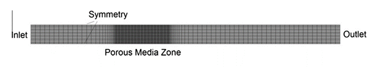
Fig. 1. Computational domain for equivalent porous media model [8]
Fig. 2. shows the 3D image of the small portion of the regenerator modelled and the periodic boundaries which are used to simulate the larger regenerator space. The use of porous formulation allows to employ a mesh system containing hexahedral grid cells. A mesh independence analysis is done before choosing the grid for all the simulations, in which pressure drop and the relative difference between the computed values are evaluated [7]. Boundary conditions are considered when porous media model simulations are carried out, like inflow boundary, outflow boundary and side boundary.
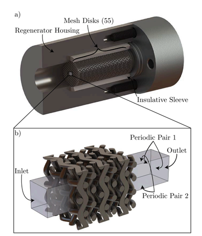
Fig. 2. a) Schematic of the full regenerator space with 55 wire mesh disks, b) modeled fluid domain and 6 wire meshes, with a velocity inlet, pressure outlet, and 2 pairs of periodic boundaries [5]
3. Results of Simulation
3.1. Pressure drop in the regenerator
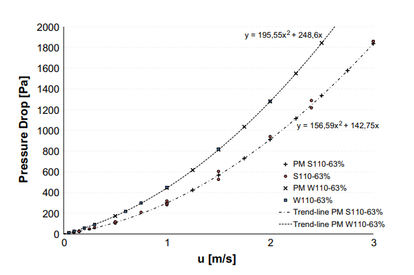
It is well known that pressure drop loss in the regenerator causes the net output power of the engine to fall [9]. With the help of modelling and simulation, we can analyze the factors affecting pressure drop. As a result, inlet velocity, which alters flow rate, has a significant influence on pressure drop, shown in Fig. 3.
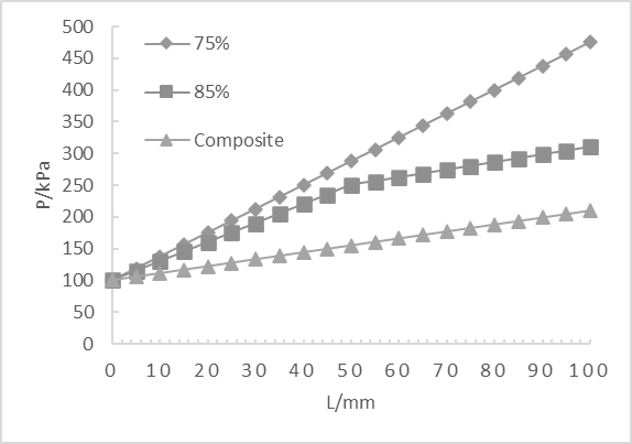
For constant flow rate, the pressure drop is mostly related to porosity and length-diameter ratio. It can be seen from Fig. 4. that the pressure drop is highest for 75% porosity and lowest for 85% porosity, the pressure drop for composite one is in the middle. To conclude, the higher the porosity, the lower the pressure drop.
As length-diameter ratio increases, the channel becomes longer, so the pressure drop at hot and cold side increases. This means resistance to flow increases, and thus more loss to flow resistance.
3.2. Heat transfer in the regenerator
In this part, a study by Mai Z. et al. [10] is introduced to better analyze the influence of materials, porosity and length-diameter ratio on heat transfer in the regenerator. Table 1 shows the parameters and scheme. 75%, 85% and composite refer to rates of porosity. Composite porosity means that 85% porosity is used near the hot chamber and 75% porosity is used near the cold chamber. 3:1 refers to the length-diameter ratio. All the scheme with the length-diameter ratio unlabeled has length diameter ratio 2:1. Fig. 5., Fig. 6. and Fig. 7. illustrate these three factors’ influences on heat transfer. Fig. 5. shows that the stainless steel regenerator has more heat flow than copper foam regenerator, but it takes more time for endothermic and exothermic lines to converge, which means that it starts out slowly. Fig. 6. shows that heat transfer in regenerator is inversely related to rates of porosity. Fig. 7. shows that an increase in length-diameter ratio has some effect on C3, like in the graph, there is an approximate 10kJ increase for heat transfer in C3 because of longer channel and corresponding large area for heat exchange. However, it has little effect on S3 for which heat has been fully exchanged.
When the flow rate increases, the heat increment first increases, but after a point, it starts to decrease. The flow rate at turning point can be considered as working flow rate when designing regenerators for better stability and efficiency.
Table 1. The structure parameters of the Sterling engine regenerators and schemes
Material | Rates of porosity and length-diameter ratio | |||
75% | 85% | composite | 3:1 | |
Copper foam | C75 | N/A | N/A | C3 |
Stainless Steel | S75 | S85 | SF | S3 |
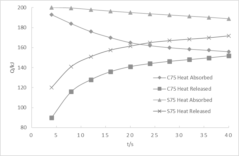
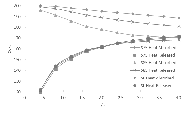
Fig. 5. Heat transfer in different materials Fig. 6. Heat transfer in different rates of porosity [10]
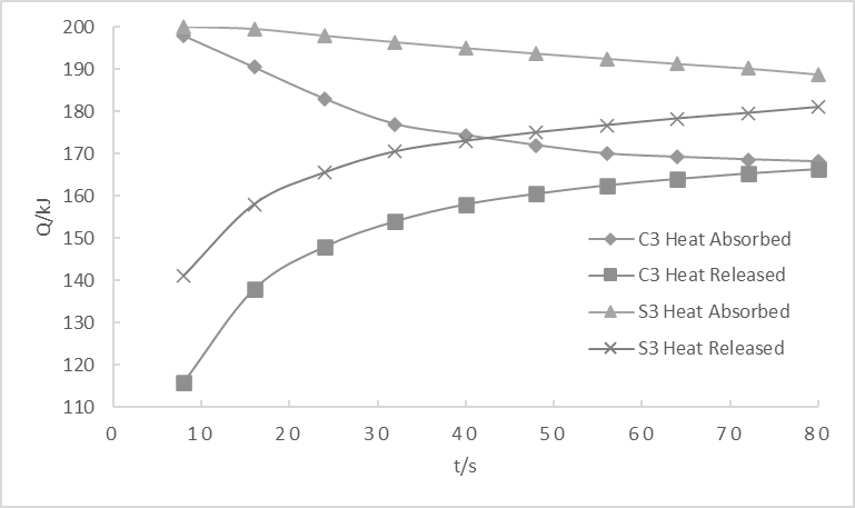
Fig. 7. Heat transfer in different length-diameter ratios
3.3. Effectiveness of regenerator
Different definitions of the effectiveness of the Stirling engine regenerator are applied when different researchers analyze Stirling engine in different ways using different models. Xu X. et al. [11] define effectiveness of regenerator as \( ε=TE-TC/TE-TC. \) By using this definition, they find out the relationship between effectiveness of regenerator and efficiency of Stirling engine- as effectiveness increases, efficiency also increases, and the percentage increase is not small, so that increasing the effectiveness of a Stirling engine regenerator is an effective way of improving the overall efficiency.
Huang H. et al. [12] introduce another way to calculate effectiveness \( η=T1g-T2g/T1g-T3g. \) T1g stands for the temperature of the working fluid when it flows to hot side. T2g stands for the temperature of the working fluid when it flows out from cold side. T3g stands for the temperature of the working fluid when it flows into cold side. As a result, they find the inverse relation between effectiveness of regenerator and rates of porosity as well as the positive correlation between effectiveness of regenerator and length-diameter ratio, and thus give some ideas for optimization.
4. Efficiency reductions resulting from other factors
4.1. Sinusoidal motion
The sinusoidal motion inside Stirling engines results in a huge decrease in the overall efficiency. This is because the deviation of the sinusoidal cycle from the ideal cycle reduces the attainable work [13]. Many studies have been down to analyze the work output from a Stirling engine operated using sinusoidal motion and effects of varying phase angle.
4.2. Dead volume
Fig. 8. illustrates the relation between efficiency of Stirling engine and dead volume ratio. As dead volume ratio increases, efficiency decreases. Nevertheless, in practical, a small dead volume ratio leads to small area for heat transfer, thus decreasing thermal efficiency of regenerator. A reasonable dead volume ratio should be selected to optimize the Stirling engine.
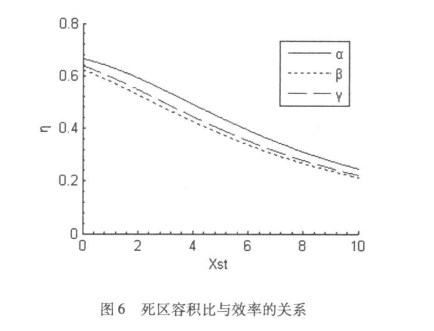
Fig. 8. Efficiency vs. dead volume ratio [11]
5. Conclusion
In this paper, theories related to modelling and factors affecting the efficiency of Stirling engine are introduced and explained in detail by summarizing and arranging different studies on Stirling engine regenerator. After a great amount of analysis, several points on optimizing regenerators can be concluded. In general, all the factors including porosity, pressure drop, heat transfer, dead volume, sinusoidal performance…should be considered when designing Stirling engine. More specifically, we want small pressure drop, small died volume ratio, quick start and good heat exchange performance. Apparently, it is not possible to satisfy all these at the same time, for example, on the one hand, we want high rates of porosity to decrease pressure drop, on the other hand, we want low rates of porosity to absorb and store more heat. Consequently, we need to come up with a compromise plan, like adopting a modest rate of porosity or utilizing composite porosity in which materials with high and low rates of porosity are combined to maximize both ones’ advantages for above case.
The final part is some suggestions for further studies on Stirling engine regenerator in the future. Firstly, information technology is developing very fast nowadays, so new methods of simulation and data calculation become available. It is a good idea to explore the prospects of novel models and numerical approaches, especially multi-dimensional ones. By using new models and algorithms, it is possible to gain more accurate data and hence better analyze the influence of those factors we discussed above on the effectiveness of regenerator and efficiency of the Stirling engine.
Another aspect is materials. Thanks to rapid advances in material science, stronger materials are available now, like ceramics and some large polymers. These materials can be used in the Stirling engine because they can withstand high temperature. A study focusing on how much can we increase the temperature and how will efficiency of Stirling engine change correspondingly can be carried on.
Last but not least, there have been many studies on heat loss due to friction, but few of them proposed possible ways to reduce heat loss. We need to work out what is the most efficient and economical way of lubricating. Furthermore, there are any materials available to form good lubricating layers. These are all of the suggestions and directions for future studies.
References
[1]. Chen J. The effect of regenerative losses on the efficiency of a Stirling heat engine at maximum power output [J] International Journal of Ambient Energy, 1997, 18:2: 107-112.
[2]. Jia M., et al. Numerical Simulation of Void Fractions Influencing Regenerator of Stirling Engine [J] Industrial Heating, 2009, 38(3): 37-39.
[3]. Ibrahim M., et al. Improving performance of the Stirling converter: redesign of the regenerator with experiments, computation and moder fabrication techniques. Cleveland State University, 2001.
[4]. Conrad T.J., et al. Anisotropic hydrodynamic parameters of regenerator materials suitable for miniature cryocoolers [C] International cryocooler conference, 2009.
[5]. Brayden T., et al. Influence of misalignment and spacing on the pressure drop through wire mesh Stirling engine regenerators [J]. Energy Conversion and Management, 2021.
[6]. Mahkamov K. Design Improvements to a Biomass Stirling Engine Using Mathematical Analysis and 3D CFD Modeling [J] Journal of Energy Resources Technology, 2006, 128: 203-215.
[7]. Maria F., et al. A Porous Media Numerical Approach for the Simulation of Stirling Engine Regenerators [J] TECNICA ITALIANA-Italian Journal of Engineering Science, 2019, 63(2-4): 291-296.
[8]. Costa S.C. et al. The thermal non-equilibrium porous media modelling for CFD study of woven wire matrix of a Stirling regenerator [J] Energy Conversion and Management, 2015, 89: 473-483.
[9]. Tanaka M., et al. Flow and Heat Transfer Characteristics of the Stirling Engine Regenerator in an Oscillating Flow [J] JSME International Journal, 1990, 33(2): 283-289.
[10]. Mai Z., et al. Performance Study of Heat Regenerators of Stirling Engines [J], Journal of Guangdong University of Technology, 2014, 31(1): 121-125.
[11]. Xu X., et al. Isothermal Model Analysis of Stirling Engine [J] Applied Energy Technology, 2011, (5): 29-34.
[12]. Huang H., et al. Performance of Regenerator of Stirling Engine [J] Journal of Nanjing University of Aeronautics & Astronautics, 2014, 46(2): 265-271.
[13]. Ranieri S., et al. Efficiency Reduction in Stirling Engines Resulting from Sinusoidal Motion [J] Energies, 2018, 11: 1-14.
Cite this article
Bo,E. (2023). Review of research on performance of stirling engine regenerators. Theoretical and Natural Science,5,922-928.
Data availability
The datasets used and/or analyzed during the current study will be available from the authors upon reasonable request.
Disclaimer/Publisher's Note
The statements, opinions and data contained in all publications are solely those of the individual author(s) and contributor(s) and not of EWA Publishing and/or the editor(s). EWA Publishing and/or the editor(s) disclaim responsibility for any injury to people or property resulting from any ideas, methods, instructions or products referred to in the content.
About volume
Volume title: Proceedings of the 2nd International Conference on Computing Innovation and Applied Physics (CONF-CIAP 2023)
© 2024 by the author(s). Licensee EWA Publishing, Oxford, UK. This article is an open access article distributed under the terms and
conditions of the Creative Commons Attribution (CC BY) license. Authors who
publish this series agree to the following terms:
1. Authors retain copyright and grant the series right of first publication with the work simultaneously licensed under a Creative Commons
Attribution License that allows others to share the work with an acknowledgment of the work's authorship and initial publication in this
series.
2. Authors are able to enter into separate, additional contractual arrangements for the non-exclusive distribution of the series's published
version of the work (e.g., post it to an institutional repository or publish it in a book), with an acknowledgment of its initial
publication in this series.
3. Authors are permitted and encouraged to post their work online (e.g., in institutional repositories or on their website) prior to and
during the submission process, as it can lead to productive exchanges, as well as earlier and greater citation of published work (See
Open access policy for details).
References
[1]. Chen J. The effect of regenerative losses on the efficiency of a Stirling heat engine at maximum power output [J] International Journal of Ambient Energy, 1997, 18:2: 107-112.
[2]. Jia M., et al. Numerical Simulation of Void Fractions Influencing Regenerator of Stirling Engine [J] Industrial Heating, 2009, 38(3): 37-39.
[3]. Ibrahim M., et al. Improving performance of the Stirling converter: redesign of the regenerator with experiments, computation and moder fabrication techniques. Cleveland State University, 2001.
[4]. Conrad T.J., et al. Anisotropic hydrodynamic parameters of regenerator materials suitable for miniature cryocoolers [C] International cryocooler conference, 2009.
[5]. Brayden T., et al. Influence of misalignment and spacing on the pressure drop through wire mesh Stirling engine regenerators [J]. Energy Conversion and Management, 2021.
[6]. Mahkamov K. Design Improvements to a Biomass Stirling Engine Using Mathematical Analysis and 3D CFD Modeling [J] Journal of Energy Resources Technology, 2006, 128: 203-215.
[7]. Maria F., et al. A Porous Media Numerical Approach for the Simulation of Stirling Engine Regenerators [J] TECNICA ITALIANA-Italian Journal of Engineering Science, 2019, 63(2-4): 291-296.
[8]. Costa S.C. et al. The thermal non-equilibrium porous media modelling for CFD study of woven wire matrix of a Stirling regenerator [J] Energy Conversion and Management, 2015, 89: 473-483.
[9]. Tanaka M., et al. Flow and Heat Transfer Characteristics of the Stirling Engine Regenerator in an Oscillating Flow [J] JSME International Journal, 1990, 33(2): 283-289.
[10]. Mai Z., et al. Performance Study of Heat Regenerators of Stirling Engines [J], Journal of Guangdong University of Technology, 2014, 31(1): 121-125.
[11]. Xu X., et al. Isothermal Model Analysis of Stirling Engine [J] Applied Energy Technology, 2011, (5): 29-34.
[12]. Huang H., et al. Performance of Regenerator of Stirling Engine [J] Journal of Nanjing University of Aeronautics & Astronautics, 2014, 46(2): 265-271.
[13]. Ranieri S., et al. Efficiency Reduction in Stirling Engines Resulting from Sinusoidal Motion [J] Energies, 2018, 11: 1-14.