


1. Introduction
With the progress of science and technology and the development of the economy, people have higher and higher requirements for the performance of electric vehicles, and research and development of electric vehicles to obtain better performance has become a popular direction. The motor is the main power source of the electric vehicle. The motor is the equipment that converts electrical energy into mechanical energy, generates rotating electromagnetic through the stator transformer, and is used for the rotor to form magnetoelectric rotation torque [1]. The motor is generally composed of a stator and a rotor, and its basic principle is that the magnetic field acts on the current to make the motor rotate [2]. The rotor is the core component of the motor to realize energy conversion.
Therefore, this paper first introduces the composition and operation principle of electric vehicle drive. The most important part of an electric vehicle is its electric motor, which is divided into three categories: pure electric vehicles, hybrid electric vehicles, and fuel cell vehicles. Pure electric vehicles run only on electricity stored in batteries and have no internal combustion engine. They use electric motors to drive the vehicle and rely on an external power source to charge the battery. Hybrid cars combine an internal combustion engine with an electric motor and battery. The internal combustion engine charges the battery and provides additional power when needed, while the electric motor assists the internal combustion engine in acceleration and low-speed conditions, improving fuel efficiency. Fuel cell vehicles use hydrogen as fuel and generate electricity through the fuel cell to drive the vehicle [3]. These cells combine hydrogen with oxygen to produce electricity and emit only water vapor, giving them the advantage of zero emissions. Therefore, this paper mainly adjusts the speed of electric vehicles by pid based on the Falstad platform to realize the adjustment of their speed and then realizes the proportional amplifier circuit in series with the same performance to reduce the use of operational amplifiers and save motor costs. On this basis, a hysteresis compensator and feedback proportional amplifier circuit are used to improve the overall performance. It is the acceleration of electric vehicles to obtain better stability.
2. Theoretical Basis
2.1. The Composition of Electric Vehicle Drive System
The electric vehicle drivetrain system consists of several components, including the battery, electric motor, transmission, and clutch. The battery is responsible for storing and supplying energy to the electric vehicle. The electric motor converts electrical energy into mechanical energy to propel the vehicle. The transmission system adjusts the vehicle's speed by facilitating the conversion of mechanical energy. The clutch ensures smooth vehicle startup, seamless shifting, and effectively prevents transmission system overload [1]. The main parameters of an electric vehicle electric motor include rated power Pe, rated speed ne, peak power, overload capacity, and maximum overload torque. The composition of the electric vehicle drivetrain system is illustrated in Figure 1.
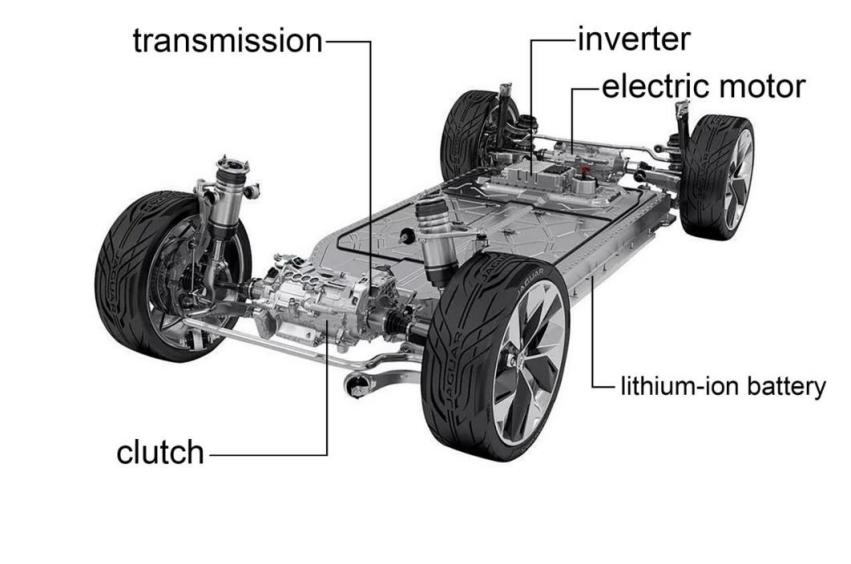
Figure 1. Composition of electric vehicle drive system (Photo/Picture credit: Original).
2.2. Operation Principle of Electric Vehicle Motor
There are three main types of electric vehicles: pure electric vehicles, hybrid electric vehicles, and fuel cell vehicles. This article focuses only on the electric motors used in pure electric vehicles. A pure electric vehicle is powered solely by a power battery, usually a lithium-ion battery, and relies on an external power source to replenish its electrical energy [4].
An electric motor is a device that converts electrical energy into mechanical energy. In addition to driving the vehicle, the electric motor in an electric vehicle also functions as a generator. Therefore, it is referred to as an electric motor. There are various types of electric motors, broadly categorized as Direct Current (DC) motors and AC motors. Due to their lower efficiency, DC motors are less commonly used [5]. This article primarily discusses AC motors, with a specific focus on AC induction motors, which are widely used in electric vehicles.
An AC induction motor consists of two main components: the rotor and the stator, which do not directly contact each other. The stator is an outer cylindrical structure with numerous windings wrapped around it. These windings are connected to the external AC power source. The entire stator is fixed to the motor housing and remains stationary. The rotor is a cylindrical or squirrel-cage structure that connects to the motor's output shaft and rotates at the same speed.
According to the characteristics of AC, when the windings on the stator are energized, a rotating magnetic field is generated. As the rotor windings are closed conductors, according to Faraday's law, when they cut through the magnetic lines of force produced by the rotating stator field, induced currents are generated in the conductors. This, in turn, generates an electromagnetic field. Therefore, there are two magnetic fields in the electric motor: the stator magnetic field and the rotor electromagnetic field. According to Lenz's law, the induced currents' magnetic field always tries to oppose the cutting of magnetic lines of force by the rotor conductors. Consequently, the rotor conductors strive to catch up with the rotating stator field, resulting in the synchronous rotation of the rotor and the stator, driving the motor's operation [6].
It is important to note that the rotor always lags slightly behind the speed of the rotating stator field to ensure the cutting of magnetic lines of force and the generation of induced currents. Therefore, the rotor's speed is always slightly lower than the speed of the stator electromagnetic field by 2% to 5%, resulting in asynchronous operation. This type of AC motor, which generates induced currents through the cutting of magnetic lines of force by the rotor conductors, is known as an "AC induction motor." The interaction between the rotating magnetic field generated by the stator windings and the induced currents produced by the rotor conductors is utilized by the AC motor to maintain its rotation. This working principle has made AC induction motors highly praised and widely used as the preferred power device in various fields. In the field of electric vehicles, AC motors are employed for motor manufacturing. Due to their simple structure, which eliminates the need for commutators and brushes, AC motors are lightweight, compact, cost-effective, and require minimal maintenance. Furthermore, their operating speeds can reach 12,000 to 15,000 rpm. The electric vehicle model is illustrated in Figure 2.
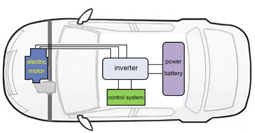
Figure 2. Electric vehicle model (Photo/Picture credit: Original).
2.3. PID Control Principle
PID control is a classic feedback control method used to regulate the system's output to a desired value. PID stands for Proportional, Integral, and Derivative, which represent the three control components. Proportional control generates the control output by multiplying the current error of the system by a proportional gain coefficient. The control output is directly proportional to the error, meaning that a larger error results in a larger output. Proportional control helps the system approach the desired value more quickly but can lead to overshoot and stability issues. Integral control generates the control output based on the accumulated error of the system by multiplying it by an integral gain coefficient. Integral control eliminates steady-state error, ensuring that the system eventually reaches the desired value. When there is persistent steady-state error, integral control gradually reduces the error until it disappears [7]. However, excessively high integral gain can cause system overshoot and instability. Derivative control generates the control output based on the rate of change of the system error by multiplying it by a derivative gain coefficient. Derivative control predicts the future response trend of the system and reduces its excessive response to changes. It improves system stability by dampening transient variations. However, derivative control is sensitive to noise, requiring appropriate filtering to smooth the input signal. The PID control principle is depicted in Figure 3.
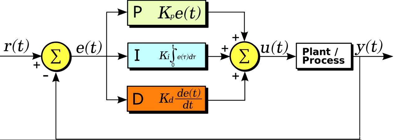
Figure 3. PID control schematic diagram [8].
The PID controller controls the controlled object by linearly combining proportional calculation, integral calculation, and derivative calculation to minimize the deviation. When tuning the parameters of the PID controller, reference can be made to the qualitative relationship between the controller parameters and the dynamic and steady-state performance of the system. To ensure safety, it is particularly important to use relatively conservative parameter settings at the beginning of debugging. Setting excessively large proportional coefficients and excessively small integral times is prohibited, as such operations may lead to instability or excessive overshoot in the control system. A step input signal can be provided to observe the output waveform of the controlled variable and obtain information about the system's performance, such as overshoot and settling time [8]. Adjust the PID parameters repeatedly based on the relationship between the PID coefficients and the system performance. If the step response exhibits excessive overshoot or oscillations, the proportional coefficient should be reduced and the integral time increased. If the step response has no overshoot but exhibits slow rise and excessively long settling time, the parameters should be adjusted in the opposite direction [9]. If the error cannot be eliminated within an ideal time frame, try reducing the integral time appropriately to enhance the integral effect. By repeatedly adjusting the parameters, if the overshoot is still significant, consider introducing derivative control and gradually increasing the derivative time. Adjust the parameters of each part of the controller repeatedly to achieve the desired control effect.
The PID control combines proportional, integral, and derivative control to consider the current error, accumulated error, and rate of change of error in order to generate the final control output. The output of the PID controller can be expressed by the following formula (1)
\( u(t)=Kp[e(t)+\frac{1}{Ti}\int _{0}^{t}〖e(t)dt+Td\frac{de(t)}{dt}]〗\ \ \ (1) \)
Where Kp is the proportional gain of the controller, Ti is the integral time or integral gain, and Td is the derivative time or derivative gain. These gain coefficients need to be adjusted based on specific applications to balance the system's response speed, stability, and disturbance rejection capability.
PID control is widely used in various industrial and automation systems, including temperature control, speed control, position control, and more [10]. It is a simple yet effective control method, but for complex systems or applications that require more advanced control strategies, a combination or improvement of other control methods may be needed.
3. Application of PID Control in Electric Vehicle Motor Speed Regulation
3.1. Integration
In electric vehicles, PID control is widely used in motor speed regulation to ensure that the motor operates at the desired speed and achieves precise control. The application of PID control in electric vehicle motor speed regulation is as follows:
(1) Torque Control: Torque control of electric vehicle motors is essential for achieving acceleration, deceleration, and stable vehicle operation. PID control can be used to measure the error between the actual torque and the desired torque of the motor, and calculate the corresponding control output to adjust the motor's torque [11]. Torque control is usually combined with speed control to enable the motor to provide the required power output according to the vehicle's demand.
(2) Anti-Lock Braking System (ABS): In the braking system of electric vehicles, PID control can also be applied to the Anti-Lock Braking System (ABS). The ABS system controls the braking force of the wheels to prevent wheel lock-up during braking, thereby improving the braking performance and stability of the vehicle. PID control can adjust the distribution of braking force based on the wheel's speed error to ensure optimal braking effect for each wheel [12].
(3) Speed Closed-Loop Control: The motor in an electric vehicle often needs to adjust its speed based on the driver's demand and the vehicle's power requirements. PID control can be used to achieve speed closed-loop control by measuring the error between the actual motor speed and the desired speed, and calculating an appropriate control output to adjust the motor's speed [13]. By tuning the proportional, integral, and derivative gains in the PID controller, accurate control of the motor speed can be achieved. Through PID control, the motor in an electric vehicle can be precisely regulated according to the actual needs, improving the vehicle's performance, safety, and energy efficiency. However, PID control also presents some challenges, such as the complexity of parameter tuning and reliance on system models. Therefore, in practical applications, it may be necessary to combine other advanced control algorithms and techniques to further optimize the speed regulation performance of electric vehicle motors [14].
This article focuses on the control of electric vehicle motor speed using PID control and aims to optimize it for improved stability.
3.2. Simulation Modeling
3.2.1. An Introduction to Falstad. Falstad is a software tool developed by Paul Falstad, primarily used for circuit simulation and visualization. It provides a user-friendly interface for designing, simulating, and analysing electronic circuits. It is known for its simplicity and versatility, making it widely popular.
In the Falstad interface, users can create circuit diagrams using various electronic components such as resistors, capacitors, transistors, and integrated circuits. It has an extensive library of components that can be easily dragged and dropped onto the circuit canvas, allowing users to construct the circuits they desire effortlessly.
One of the key features of Falstad is its circuit simulation capability. Once the circuit is designed, users can run simulations to observe the behaviour of the circuit under different conditions. These simulations provide insights into various electrical characteristics such as voltage, current, power, and frequency response, allowing users to experiment with different circuit configurations and parameters, aiding in understanding circuit theory and troubleshooting effectively. The visualization capabilities of Falstad also help users to intuitively understand circuit behaviour. It provides animated voltage and current waveforms, phasor diagrams, and frequency response plots, enabling users to visually observe circuit characteristics. Furthermore, Falstad supports educational purposes by providing built-in examples and tutorials that cover a wide range of electronic circuits, such as amplifiers, filters, oscillators, and digital logic circuits, among others. These resources are valuable for electronic circuit students and scholars exploring circuitry.
In summary, Falstad is a feature-rich and user-friendly circuit simulation tool. Its intuitive interface, real-time simulation capabilities, and visualizations make it an excellent choice for beginners and professionals in the field of electronics, widely used in educational and research exploration.
3.2.2. Proportional-Integral (PI) Closed-Loop Control Model of a DC Motor. The diagram below represents the proportional-integral (PI) closed-loop control model of a DC motor. The circuit is composed of three parts. The first part is the error computation section, where a proportional amplifier circuit is used to amplify the sum of the desired velocity and the negative value of the feedback velocity. The desired velocity is generated by a square wave module. The second part is the PI controller section, which is used to calibrate and adjust the motor system. The resistor in the PI controller provides the proportional component, while the capacitor provides the integral component. The third part is the motor model section, where a first-order inertia system is constructed using a feedback amplifier circuit to simulate the velocity variation of the motor. The time constant of the capacitor is related to the time constant of the inertia system.
The PI controller is an essential component in achieving closed-loop regulation. Its transfer function can be represented as follows:
\( \frac{{u_{o}}(s)}{{u_{i}}(s)}=\frac{\frac{1}{jwc}+{R_{f1}}}{{R_{i1}}}\frac{{R_{f2}}}{{R_{i2}}}=5+\frac{100}{s}\ \ \ (2) \)
The simulation graph is shown in Figure 4.
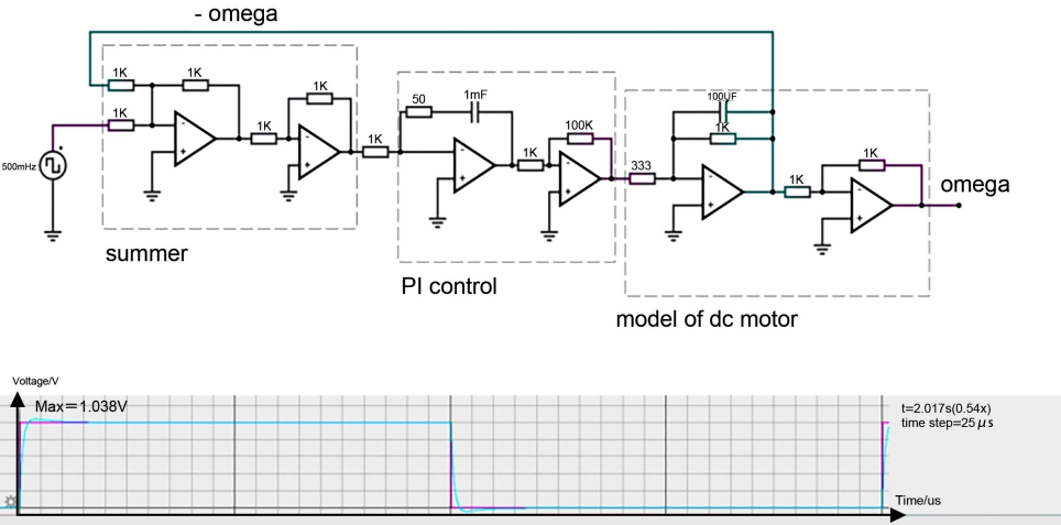
Figure 4. Proportional-Integral (PI) Closed-Loop Control Model of a DC Motor(Photo/Picture credit: Original).
As shown in the figure, the horizontal axis represents time, and the vertical axis represents voltage. The green line represents the input value and its variation, while the red line represents the output value and its variation. Due to the presence of overshoot and the influence of delay factors, the red line exhibits fluctuations. The steep drop in the middle line indicates the zeroing of the input value, leading to the zeroing of the output value, followed by a new control cycle.
3.2.3. Simplified Circuit Implementation for PI Control of a DC Motor. This part mainly simplifies some unnecessary components to reduce complexity and save design and manufacturing costs. The error computation section and the PI controller section are both composed of feedback proportional amplification circuits. The output voltage of the feedback proportional amplification circuit is opposite in polarity to the input voltage. Therefore, in the previous circuit, both the error computation section and the PI controller section used two-stage feedback proportional amplification circuits to achieve the desired functionality. The second-stage feedback proportional amplification circuit in the PI controller section is primarily used for voltage polarity adjustment. By directly connecting the two proportional amplification circuits in series, the original functionality can be achieved while reducing the number of operational amplifiers and simplifying the circuit. Before the simplification, the second-stage feedback proportional amplification circuit in the PI controller section not only adjusted the voltage polarity but also amplified the function. Therefore, after simplification, some modifications need to be made to the PI controller section. The corrected transfer function calculation process is as follows:
\( \frac{{u_{o}}(s)}{{u_{i}}(s)}=-\frac{\frac{1}{jwc}+{R_{f}}}{{R_{i}}}=5+\frac{100}{s}\ \ \ (3) \)
The simulation graph is shown in Figure 5.
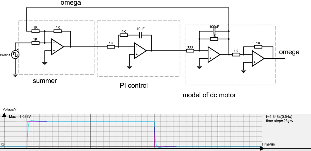
Figure 5. Simplified Circuit Implementation for PI Control of a DC Motor(Photo/Picture credit: Original).
In this diagram, we can see a graph depicting the relationship between time and voltage. The horizontal axis represents time, while the vertical axis represents voltage. The green line represents the input value and its changes, while the red line represents the output value and its changes. Due to the presence of overshoot and delay factors, the red line exhibits fluctuations. The sharp drop in the middle indicates the input value returning to zero, resulting in the output value also returning to zero, followed by the start of a new control cycle.
3.2.4. Enhanced Performance through Second-Order Motor Model and Lag Compensator Circuit. In order to design a more complex circuit and attempt to improve its performance, the error computation section remains the same as in the previous circuit. However, the motor model section needs to be changed from a first-order system to a second-order system. The controller section consists of two cascaded first-order inertial systems, forming a lag compensator that provides series compensation to the control system. Each first-order inertial system is implemented using a feedback proportional amplification circuit. In the feedback loop, a capacitor and a resistor are connected in parallel, and the values of the capacitor and resistor in the feedback proportional amplification circuit are adjusted to compensate for the phase variation of the open-loop system. This adjustment enhances the phase margin of the system and improves its stability. The simulation graph is shown in Figure 6.
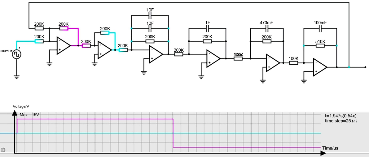
Figure 6. Second-order motor model and hysteresis compensation circuit(Photo/Picture credit: Original).
This graph illustrates the relationship between time and voltage. Time is represented on the horizontal axis, while voltage is represented on the vertical axis. The green line represents the input value and its variations, while the red line represents the output value and its fluctuations. Due to the influence of overshoot and delay, the red line exhibits a waveform pattern. The sharp drop in the middle signifies the input value returning to zero, resulting in the output value also reaching zero, followed by the initiation of a new control cycle.
4. Conclusion
This article discusses the application of PID control in electric vehicle motor control. PID control is a widely adopted control technique that allows for precise control of motor speed and overall performance based on feedback signals. By continuously monitoring and adjusting control parameters, PID control optimizes motor operation and improves performance. It has found extensive use in the automotive industry due to its effectiveness. The accuracy and reliability of PID control contribute to enhanced vehicle speed control and improved driving experience. As the demand for electric vehicles continues to rise, PID control plays a crucial role in ensuring motor performance.
Although PID control is widely applied and significantly enhances motor performance, it has certain limitations. PID control requires high precision in parameter tuning, which can be time-consuming and require expertise. Furthermore, it struggles to handle complex nonlinear systems due to the indirect relationship between inputs and outputs. To overcome these limitations, advanced control techniques such as fuzzy control and adaptive control algorithms need to be further explored to improve the control accuracy and adaptability of motion control systems. Additionally, combining artificial intelligence with PID control holds promise for overcoming its limitations and enabling self-improvement. The future of electric vehicle motor control lies in the development of hybrid control systems, which combine the strengths of PID control with intelligent algorithms to achieve precise and adaptive control even under challenging conditions.
References
[1]. Zhang Shucheng, Lu Lei, Liu Cheng. Optimized Design of Working Parameters for Electric Vehicle Motors. Journal of Huangshan University, 2022, 24(05):17-19.
[2]. Gao Peng. Design and Research of Permanent Magnet Hub Motor for Electric Vehicles. Tianjin University, 2015.
[3]. Zhou Tuo. Thermal Analysis and Optimization of Electric Air Compressor for Fuel Cell Applications. Shandong University, 2021.
[4]. Li Weishuo. Exploration of Range Improvement in Pure Electric Vehicles. Zhongguancun, 2023, No.238(03):102-103.
[5]. Li Wei. Research on Control Strategy for Integrated Drive System of Electric Motor and Transmission in Light Electric Vehicles. Wuhan University of Technology, 2011.
[6]. Xu Weihao. Design and Torque Ripple Suppression Research of Wound Rotor Brushless Doubly Fed Motor. Harbin University of Science and Technology, 2022.
[7]. Zheng Weijia. Research on Fractional Order Modeling and Control of Permanent Magnet Synchronous Motors. South China University of Technology, 2016.
[8]. Yu Boxuan. Exploration of Energy-saving Controller for Electric Vehicles Based on Energy-saving Concept. Technology and innovation, 2020, No.162(18):50-51+53.
[9]. Xia Jiakuan, Wang Dapeng. Research on Single-Parameter Fuzzy PID Excitation Controller for Synchronous Motors. Marine electric technology, 2007, No.147(02):69-71.
[10]. Zhao Zhicheng, Yang Yateng, Zhang Jinggang. Research on Fuzzy Fractional-Order Internal Model PID Control Method for AC Speed Control Systems. Control engineering:1-6[2023-07-02].
[11]. Liu Hui, Xu Haoxin, Zhang Xun. Fuzzy PID Direct Torque Control of Hybrid Vehicle's Flexible Transmission System. Mechanical Design and Manufacturing, 2022, No.378(08):173-180.
[12]. Zhang Dahai. Research on Fuzzy PID Control for Anti-lock Braking System in Automobiles. Shenyang University of Technology,2022.
[13]. Wang Youqing, Tian Yongtao, Wang Zhanhang et al. Implementation of Motor Speed Closed-Loop Control Using PLC. Machine Tools and Hydraulics,2002(03):28-29.
[14]. Zhao Pengfei, Yu Jianding, Wu Xin et al. Design of Closed-Loop Control System for Sensorless DC Motor. Journal of Ningbo University (Science and Engineering Edition),2014,27(02):59-63.
Cite this article
Zhu,Q. (2023). Speed regulation of electric vehicle motor based on PID control. Theoretical and Natural Science,9,91-99.
Data availability
The datasets used and/or analyzed during the current study will be available from the authors upon reasonable request.
Disclaimer/Publisher's Note
The statements, opinions and data contained in all publications are solely those of the individual author(s) and contributor(s) and not of EWA Publishing and/or the editor(s). EWA Publishing and/or the editor(s) disclaim responsibility for any injury to people or property resulting from any ideas, methods, instructions or products referred to in the content.
About volume
Volume title: Proceedings of the 3rd International Conference on Computing Innovation and Applied Physics
© 2024 by the author(s). Licensee EWA Publishing, Oxford, UK. This article is an open access article distributed under the terms and
conditions of the Creative Commons Attribution (CC BY) license. Authors who
publish this series agree to the following terms:
1. Authors retain copyright and grant the series right of first publication with the work simultaneously licensed under a Creative Commons
Attribution License that allows others to share the work with an acknowledgment of the work's authorship and initial publication in this
series.
2. Authors are able to enter into separate, additional contractual arrangements for the non-exclusive distribution of the series's published
version of the work (e.g., post it to an institutional repository or publish it in a book), with an acknowledgment of its initial
publication in this series.
3. Authors are permitted and encouraged to post their work online (e.g., in institutional repositories or on their website) prior to and
during the submission process, as it can lead to productive exchanges, as well as earlier and greater citation of published work (See
Open access policy for details).
References
[1]. Zhang Shucheng, Lu Lei, Liu Cheng. Optimized Design of Working Parameters for Electric Vehicle Motors. Journal of Huangshan University, 2022, 24(05):17-19.
[2]. Gao Peng. Design and Research of Permanent Magnet Hub Motor for Electric Vehicles. Tianjin University, 2015.
[3]. Zhou Tuo. Thermal Analysis and Optimization of Electric Air Compressor for Fuel Cell Applications. Shandong University, 2021.
[4]. Li Weishuo. Exploration of Range Improvement in Pure Electric Vehicles. Zhongguancun, 2023, No.238(03):102-103.
[5]. Li Wei. Research on Control Strategy for Integrated Drive System of Electric Motor and Transmission in Light Electric Vehicles. Wuhan University of Technology, 2011.
[6]. Xu Weihao. Design and Torque Ripple Suppression Research of Wound Rotor Brushless Doubly Fed Motor. Harbin University of Science and Technology, 2022.
[7]. Zheng Weijia. Research on Fractional Order Modeling and Control of Permanent Magnet Synchronous Motors. South China University of Technology, 2016.
[8]. Yu Boxuan. Exploration of Energy-saving Controller for Electric Vehicles Based on Energy-saving Concept. Technology and innovation, 2020, No.162(18):50-51+53.
[9]. Xia Jiakuan, Wang Dapeng. Research on Single-Parameter Fuzzy PID Excitation Controller for Synchronous Motors. Marine electric technology, 2007, No.147(02):69-71.
[10]. Zhao Zhicheng, Yang Yateng, Zhang Jinggang. Research on Fuzzy Fractional-Order Internal Model PID Control Method for AC Speed Control Systems. Control engineering:1-6[2023-07-02].
[11]. Liu Hui, Xu Haoxin, Zhang Xun. Fuzzy PID Direct Torque Control of Hybrid Vehicle's Flexible Transmission System. Mechanical Design and Manufacturing, 2022, No.378(08):173-180.
[12]. Zhang Dahai. Research on Fuzzy PID Control for Anti-lock Braking System in Automobiles. Shenyang University of Technology,2022.
[13]. Wang Youqing, Tian Yongtao, Wang Zhanhang et al. Implementation of Motor Speed Closed-Loop Control Using PLC. Machine Tools and Hydraulics,2002(03):28-29.
[14]. Zhao Pengfei, Yu Jianding, Wu Xin et al. Design of Closed-Loop Control System for Sensorless DC Motor. Journal of Ningbo University (Science and Engineering Edition),2014,27(02):59-63.