


1. Introduction
There are many different aeroengines: turbojet engines, turbofan engines, turboprop engines, turboshaft engines, and ramjet engines. The turbofan and turbojet engines are the main ones that serve different places, for example, for military and commercial use. An aeroengine is an extremely complex machine. Aircraft engines must be designed to operate continuously and stably under high temperatures and pressure and have a high service life. Therefore, the design of aeroengines is extremely difficult for a series of disciplines such as aerodynamics, materials science, thermodynamics and so on. The technology of the aeroengine is the technological crystallization of an era, and it will also promote the improvement of people's quality of life and the development of the national economy. At 18 century, Isaac Newton formulated Newton’s third law, which is that when two bodies interact, they exert equal and opposite forces on each other.
Newton’s third law provides the basic turbojet and turbofan engine theory. In the 1930s, British pilot Frank Whittle designed the first turbojet engine, which had the same design as the current one, using a sequence of air intake, compressor, combustor, turbine and nozzle [1]. The International Civil Aviation Organization (ICAO) is a United Nations agency. It serves for global aviation network. According to the International Civil Aviation Organization (ICAO), passenger traffic in the world of air transport in 2021 increase by 22.4%. Especially in North America, air transport took 32% of the world and increased by 72.6% compared to 2020 [2]. As people rely increasingly on air transportation, safety and comfort become important. This article uses the basic thermodynamics theory to analyze the difference between turbojet and turbofan engines and the possible future development of airplane engines.
2. Turbojet engine
The Turbojet engine is shown in Figure 1: air intake at stage 1 goes through the low-pressure compressor, stage 2 and then passes through stage 3, the high-pressure compressor. There are many small blades on the compressor. There are two types of blades, compressor rotor (work blade) and compressor stator (guide blade), in which the rotor can spin at high speed and the stator cannot spin. The order is that a rotor and a stator combine to form a group, and another group follows a group. The air will pass through the rotor first, which will do work to the intake air to increase the kinetic energy of the air, then air passes through the stator, which will decrease the intake air velocity to increase the pressure. Also, the station will guide the airflow to a certain direction and the next blade group. After passing through several blade groups, the air would be denser, and the temperature and pressure of it will reach the point suitable for continuous combustion [3]. Then the squeezed air will go through the combustion chamber, stage 4. The fuel injector will inject the atomized fuel, which can mix with squeezed air, and the mixture will be set on fire. The mixture will expand quickly and be ejected from the nozzle in a high-speed and high-temperature state to form a jet flow. The jet flow will spin the turbine behind the combustor, which is connected to the compressor by a shaft, which means the jet flow drives the compressor. The jet flow is blown out of the nozzle's end, producing the reverse thrust [1].
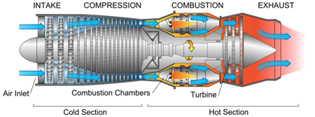
Figure 1. Turbojet engine cross-section, reproduced from the website: https://www.mech4study.co-m/wp-content/uploads/2019/02/LheHE.png?ezimgfmt=ng:webp/ngcb1
This production of thrust is similar to a balloon full of air. A man holds the balloon so the air inside does not go out. At this state, the force at the inner side of the balloon is balanced everywhere, assuming the balloon is a perfect circle. When the man loose hand, which causes the force of the inner side of the balloon to lose balance, the air will expand, be accelerated, and run out of the hole. The force of the airflow gives the balloon a backward force. The force will cause a magnitude equal, opposite direction force that will push the balloon moving to the opposite way of the direction of airflow. This example explains how the jet flow from the nozzle can push the engine and airplane body forward. According to Newton’s second law: The external force on the body is equal to the product of the mass and the acceleration, and the acceleration is in the same direction as the external force.
\( F=M({V_{0}}-V) \) (1)
F is the force exerted on the subject. M is the mass flow rate. V_0 is the air that flows into the engine. V is the air that flows out of the engine [2]. Since this is the interaction force, the magnitude of thrust should be equal to the magnitude of F but in a different direction, which means thrust P is equal to negative F.
\( P=-F=M(V-{V_{0}}) \) (2)
The nozzle is narrow at the outlet, since mass flow rate is equal to density times velocity, and times area, transform this equation into velocity equal to mass flow rate divide the product of density and area [4].
\( \dot{m}= ρ*A*V \) (3)
\( V=\frac{\dot{m}}{ρ*A} \) (4)
M dot is the volumetric flow rate and ρ is the density of the object. A is the area through which mass flows. V is the velocity of the flowing air.
Narrowing the nozzle's outlet area is one solution to achieve a higher outlet speed. The turbojet engine has no outer channel, meaning it has no bypass ratio. The turbojet engine produces thrust by the jet flow, so it needs an extremely high burning temperature to achieve a higher thrust, which means the compressor has to do more work to compress the intake air to achieve a higher temperature and pressure. Furthermore, the drag will rise significantly when the warcraft’s speed approaches the sound speed. To overcome this issue, engineers install an afterburner behind the turbine, injecting extra fuel into the jet flow and been ignited to produce more thrust [5,6]. Thus, the turbojet engine will consume much more fuel than the turbofan engine, which means only the military can afford this high fuel-consuming.
3. Turbofan engine
The turbofan engine works similarly to the turbojet engine. The difference is that there is a big fan in front of the turbofan engine and a low-pressure turbine behind the combustion chamber (Figure 2). The low-pressure channel drives the fan, and the high-pressure channel drives the compressor. According to graph two, the fan, compressor, high-pressure, and low-pressure turbine are on the same shaft. The gearbox separates the fan and low-pressure turbine from the compressor and the high-pressure turbine so that the fan can run at a different speed, saving more energy. The air is sucked in by the big fan and separated into the inner channel and the outer channel. The air passing through the outer channel will be accelerated to achieve a higher thrust. The air passing through the outer channel is much cooler than the air of the inner channel since the inner channel will ignite the mixture of air and fuel. The fan and the outer channel combine to produce most of the turbofan engine thrust. The jet flow of the inner channel is mainly used to drive low-pressure and high-pressure turbines [7,8].
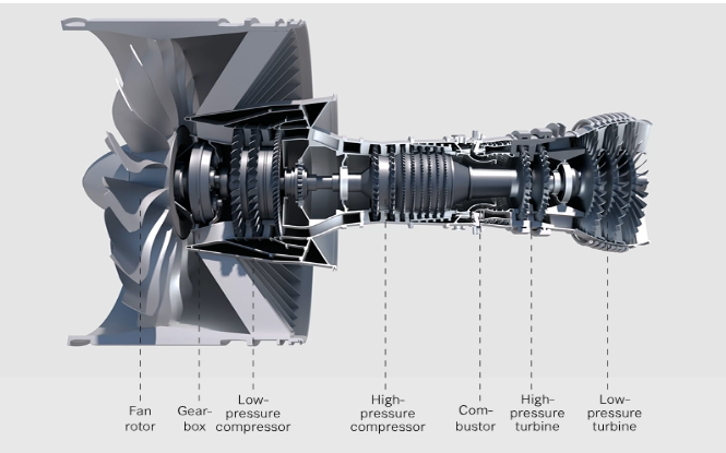
Figure 2. The cross-section of the turbofan engine, reproduced from the website: https://aeroreport.de/en/good-to-know/how-does-a-turbofan-engine-work-the-structure-of-an-engine
The bypass ratio is a very important concept of turbofan engines. The ratio between the air going through the inner and outer channels is called the bypass ratio. The bypass ratio can affect the fuel-consuming and flying speed of an airplane. As this article mentioned, the thrust of a turbojet engine is produced by the jet flow, which is the air after burning. This will cause high fuel consumption and large engine emissions. Rising fuel costs, increasing environmental awareness, and pressure to reduce noise levels around airports finally led to developing the high bypass ratio engines (Figure 3).
Turbofan engine, which has a high bypass ratio, consumes less fuel while doing low-speed flying, but, at the same time, the performance of high-speed flying will be worse since the larger the bypass ratio, the larger the engine volume. Thus, the high bypass ratio turbofan engine is widely applied by public transportation and logistics transportation.
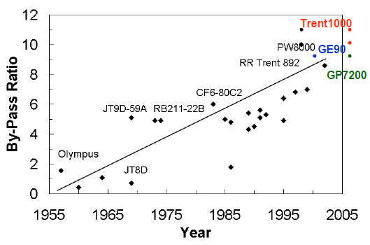
Figure 3. Development of Turbofan Engine Bypass Ratio. Reproduced from the website: https://www.researchgate.net/publication/306082636_Performance_Analysis_of_High_Bypass_Ratio_Turbofan_Aeroengine
Turbofan engine, which has a low bypass ratio, still consumes less fuel than the basic turbojet engine [9]. The lower bypass ratio means less engine volume, allowing the fighter jet to have a smaller fuselage. The smaller fuselage can allow the fighter jet to travel at a higher speed since the smaller fuselage has smaller air resistance. Thus, some fighter planes are low bypass ration turbofan engines serving the military. Furthermore, the modern fighter plane has an afterburner behind the turbine, which will further enhance the maneuverability of the fighter plane and make it more suitable for air combat [9].
4. Future development
Since turbofan engine is widely used in commercial transportation, safety and comfort have become the main development of this engine.
1.1. Comfort
The commercial use of turbofan engines is becoming increasingly quiet (Figure 4). As airplanes develop, the noise produced by the engines is gradually reduced. The turbofan engine noise mainly comes from the big fan and the exhaust (nozzle) [10].
The spinning fan blade will keep pushing the air to hit the stator of the compressor, then generate an unsteady load, and the periodic (since the blade keeps spinning) unsteady load produces a sound wave, which is noise. The engineers tried to analyze the relationship between the number of blades of the fan and the outlet guide vans, which are located after the fan case assembly. Engineers experimented with 55 outlet guide vans and 37 outlet guide vans and found that only one first-order acoustic mode can propagate in the fan duct, meaning 55 vans created less sound (noise) than 37 vans. This experiment is based on the acoustic modal cutoff theory of Tyler and Sofrin [8].
1.2. Safety
There was a case that happened on Jun 24, 1982. A Boeing 747-236B is flown near Mount Kalungung, an active volcano in West Java, Indonesia. The ash from an active volcano is very hard. Ash can scratch a plane's windshield at high speeds, blocking the pilot's view. Volcanic ash damage to engine engines is also very serious. Much ash enters the engine with air. The ash is melted at high temperatures in the combustion chamber and turbine, and it solidifies in the exhaust pipe because of the decrease in temperature, interfering with the engine's airflow. This caused the aircraft engine to stall, but fortunately, no one was injured in the accident. After the accident, ash appeared on satellite weather photos to ensure that aircraft were no longer affected [11].
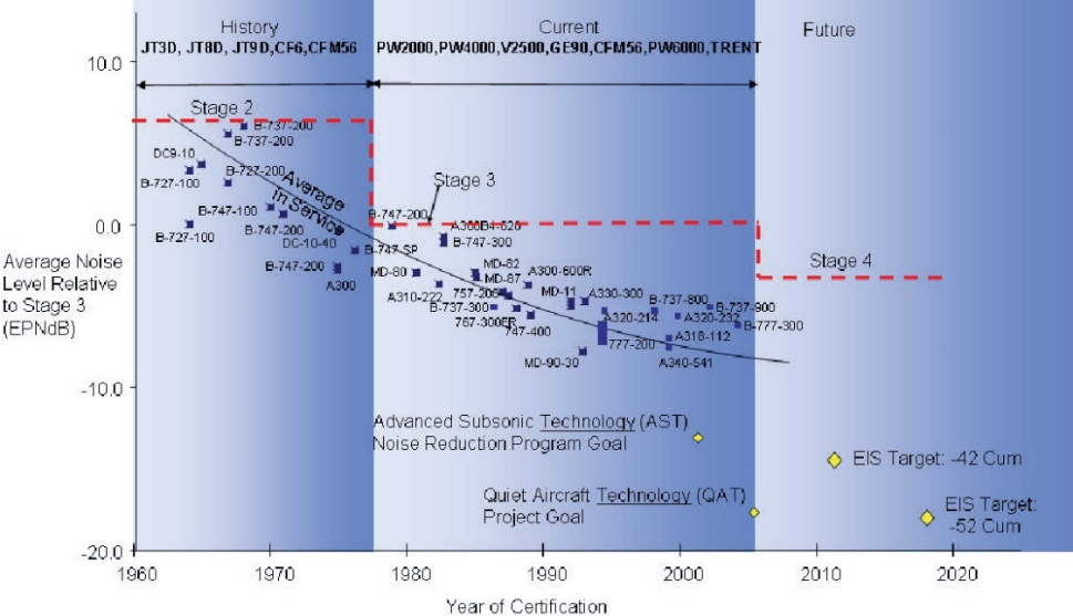
Figure 4. Noise reduction technologies for turbofan engines [10].
2. Conclusion
As this article discussed, the turbofan engine is suitable for commercial use since it has a higher bypass ratio and lower fuel consumption, but a larger engine volume does not allow it to travel at high speeds, such as supersonic speed. Meanwhile, a low bypass ratio turbofan engine can also be military used since it has smaller volume (smaller air resistance) and less fuel consumption. The turbojet engine can travel at a supersonic speed since it has a higher burning temperature and higher pressure, which means the jet flow will be extremely fast, but it consumes much more fuel than the turbofan engine, so the military mainly uses it.
In the future, the engineer would improve the safety and comfort of the turbofan engine, for example, by lowering the engine's noise and preventing the airplane from passing through dangerous zones. Turbofan is the main means of modern commercial use, so various companies and countries will try to develop turbofan engines. With the improvement of people's environmental awareness, turbofans are fuel efficient compared to their aero engines, so to save energy, the development of turbofans is the best choice.
References
[1]. Dr. Robert J. Shaw. How does a jet engine work? May 13, 2021. Retrieved on Jul 9, 2023. Retrieved from: https://www.grc.nasa.gov/www/k-12/UEET/StudentSite/engines.html#
[2]. ICAO. The World of Air Transport in 2021. 2021. Retrieved on Jul 9, 2023. Retrieved from: https://www.icao.int/sustainability/WorldofAirTransport/Pages/the-world-of-air-transport-in-2021.aspx
[3]. Liu D and Chen G 2003 Aeroengine: The heart of the aircraft. Aviation Industry Press. pp 59-104
[4]. Moran M and Shapiro H Fundamentals of engineering thermodynamics McGraw-Hill Book Co p 142
[5]. Ma M, Jin J and Ji H 2008 Aero engine afterburner technology and novel structure scheme Gas Turbine Test and Research 4 55
[6]. Nancy H Afterburning Turbojet. May 13, 2021. Retrieved on Jul 9, 2023. Retrieved from: https://www.grc.nasa.gov/www/k-12/airplane/Animation/turbtyp/etar.html
[7]. Chen J 2018 Overview of the working principle and application of turbofan engines Times Motor 5 115
[8]. Li D and Yang X 2013 Low Noise design of a large bypass ratio turbofan engine Proceedings of the 3rd Shanghai - Xi 'an Acoustical Society Conference 32 157-158
[9]. Nancy Hall. Turbofan engine. May 13, 2021. Retrieved on Jul 9, 2023. Retrieved from:https://www.grc.nasa.gov/www/k-12/airplane/aturbf.html#:~:text=Because%20the%20fuel%20flow%20rate,turbofan%20is%20very%20fuel%20efficient
[10]. Glenn D 2006 Noise Reduction Technologies for Turbofan Engines p 5
[11]. Code 7700. Feb 22, 2018. Retrieved on Jul 9, 2023. Retrieved from: https://code7700.com/case_study_british_airways_9.htm#section1
Cite this article
Wei,K. (2023). Turbofan and turbojet engines: Working process and future development. Theoretical and Natural Science,12,114-119.
Data availability
The datasets used and/or analyzed during the current study will be available from the authors upon reasonable request.
Disclaimer/Publisher's Note
The statements, opinions and data contained in all publications are solely those of the individual author(s) and contributor(s) and not of EWA Publishing and/or the editor(s). EWA Publishing and/or the editor(s) disclaim responsibility for any injury to people or property resulting from any ideas, methods, instructions or products referred to in the content.
About volume
Volume title: Proceedings of the 2023 International Conference on Mathematical Physics and Computational Simulation
© 2024 by the author(s). Licensee EWA Publishing, Oxford, UK. This article is an open access article distributed under the terms and
conditions of the Creative Commons Attribution (CC BY) license. Authors who
publish this series agree to the following terms:
1. Authors retain copyright and grant the series right of first publication with the work simultaneously licensed under a Creative Commons
Attribution License that allows others to share the work with an acknowledgment of the work's authorship and initial publication in this
series.
2. Authors are able to enter into separate, additional contractual arrangements for the non-exclusive distribution of the series's published
version of the work (e.g., post it to an institutional repository or publish it in a book), with an acknowledgment of its initial
publication in this series.
3. Authors are permitted and encouraged to post their work online (e.g., in institutional repositories or on their website) prior to and
during the submission process, as it can lead to productive exchanges, as well as earlier and greater citation of published work (See
Open access policy for details).
References
[1]. Dr. Robert J. Shaw. How does a jet engine work? May 13, 2021. Retrieved on Jul 9, 2023. Retrieved from: https://www.grc.nasa.gov/www/k-12/UEET/StudentSite/engines.html#
[2]. ICAO. The World of Air Transport in 2021. 2021. Retrieved on Jul 9, 2023. Retrieved from: https://www.icao.int/sustainability/WorldofAirTransport/Pages/the-world-of-air-transport-in-2021.aspx
[3]. Liu D and Chen G 2003 Aeroengine: The heart of the aircraft. Aviation Industry Press. pp 59-104
[4]. Moran M and Shapiro H Fundamentals of engineering thermodynamics McGraw-Hill Book Co p 142
[5]. Ma M, Jin J and Ji H 2008 Aero engine afterburner technology and novel structure scheme Gas Turbine Test and Research 4 55
[6]. Nancy H Afterburning Turbojet. May 13, 2021. Retrieved on Jul 9, 2023. Retrieved from: https://www.grc.nasa.gov/www/k-12/airplane/Animation/turbtyp/etar.html
[7]. Chen J 2018 Overview of the working principle and application of turbofan engines Times Motor 5 115
[8]. Li D and Yang X 2013 Low Noise design of a large bypass ratio turbofan engine Proceedings of the 3rd Shanghai - Xi 'an Acoustical Society Conference 32 157-158
[9]. Nancy Hall. Turbofan engine. May 13, 2021. Retrieved on Jul 9, 2023. Retrieved from:https://www.grc.nasa.gov/www/k-12/airplane/aturbf.html#:~:text=Because%20the%20fuel%20flow%20rate,turbofan%20is%20very%20fuel%20efficient
[10]. Glenn D 2006 Noise Reduction Technologies for Turbofan Engines p 5
[11]. Code 7700. Feb 22, 2018. Retrieved on Jul 9, 2023. Retrieved from: https://code7700.com/case_study_british_airways_9.htm#section1