


1. Introduction
In recent years, with the gradual development of the aviation industry, how to make supersonic aircraft truly used in military air defense has become a global problem. In this paper, the wing design of supersonic aircraft will be studied, and a composite wing suitable for supersonic reconnaissance aircraft will be designed. The initial parameters related to wing design will be assumed, including the preliminary estimation of lift drag characteristics, thrust weight ratio and wing load; then the wing parameters will be analyzed in detail, and the geometric parameters of the wing, lift increasing device, aileron, tail and control surface will be selected; finally, the design and analysis of the control system will be carried out, including the aerodynamic characteristics of the wing, the balance and stability of the aircraft and the flight performance. This design may provide a possibility for the wing design of supersonic reconnaissance aircraft in the future.
2. Initial overall parameter design
2.1. Preliminary estimation process of lift and drag characteristics
Composite materials, can be defined as to any material, and they consists of strong fibers either they are continuous or discontinuous and are sticked using weaker matrix. Composite material is preferable to replace other homogeneous metallic because of the low manufacturing cost, high tensile and compressive strength, and light weight. All these features benefit aircraft manufacturing since it will reduce cost of maintenance and fuel consumption [1].
2.1.1. Assume the value of maximum lift coefficient. Generally, the takeoff maximum lift coefficient is about 80% of the landing maximum lift coefficient. According to the typical value table of maximum lift coefficient - the coefficient value range of fighter:
Maximum lift coefficient ( \( {C_{Lmax}} \) ):1.2-1.8, Value 1.6;
Landing maximum lift coefficient ( \( {C_{LmaxL}} \) ):1.6-2.6, Value 2.4;
Takeoff maximum lift coefficient ( \( {C_{LmaxTO}} \) ):1.4-2.0;
\( {C_{LmaxTO}}={C_{LmaxL}}×0.8=1.92 \) (1)
2.1.2. Zero lift drag coefficient. Zero lift resistance formula estimated by equivalent skin friction coefficient method:
\( {C_{do}}={C_{fe}}×(wetted \prime area/refenrence \prime area) \) (2)
\( {C_{fe}} \) : Equivalent skin friction coefficient
Since the design plane area of the aircraft cannot be determined at the estimation stage, the statistical value is used to estimate:
Wetted area/reference area is temporarily taken as 2.4 in the estimation stage
\( {C_{do}}=0.004×2.4=0.0096 \) (3)
2.1.3. Determine the maximum lift drag ratio. Aircraft drag coefficient:
\( {C_{d}}={C_{do}}+{{C_{L}}^{2}}/(π×A×e) \) (4)
A is the aspect ratio of the wing: take 3.25 (the aspect ratio of supersonic fighter is generally 2~4), E is Oswald efficiency factor, which is calculated as follows:
Bentwing
\( e=4.61×(1-0.045×{A^{0.68}}){(cos{J}ILE)^{0.1}}-3.1 \) (5)
ЛLEis the swept angle of the leading edge of the wing: 60°
Hence,
\( e=4.61×(1-0.045×3.2{5^{0.68}}){(cos{6}0°)^{0.1}}-3.1=0.64 \) (6)
Lift drag ratio directly depends on two design factors: wing span and wetted area. At subsonic speed, the formula of the maximum lift drag ratio can be used to estimate the lift drag ratio L/D:
\( {(L/D){(π×A×e/{C_{do}})^{0.5}}_{max}} \) (7)
The relevant data of lift drag ratio are listed in Table 1 below.
Table 1. Lift drag ratio characteristic value table.
\( {C_{LmaxL}} \) | 1.2-1.8 | 1.6 |
\( {C_{LmaxL}} \) | 1.6-2.6 | 2.4 |
\( {C_{LmaxTO}} \) | \( 1.4-2.0(=0.8×{C_{LmaxL}}) \) ) | 1.92 |
Saturation aspect ratio | \( \frac{wing \prime spa{n^{2}}}{wetted \prime area}=\frac{wing \prime aspect \prime ratio}{wetted \prime area} \) | 1.02 |
Infiltration area ratio | Wetted area/Reference area | 2.4 |
Equivalent skin friction coefficient \( {C_{fe}} \) | fleet fighter | 0.004 |
\( {C_{do}} \) | \( {C_{fe}}×(wetted \prime area/refenrence \prime area) \) | 0.0096 |
Aspect ratio A | 2~4 | 3.25 |
Leading edge sweep angle | 60° | 60 |
Oswald efficiency factor | In cruise state, approximately taken as \( e=0.6-0.85 \) | 0.64 |
The maximum lift drag ratio | \( 0.5{(π×A×e/{C_{do}})^{0.5}} \) | 13.025009 |
2.2. Thrust weight ratio and wing load
2.2.1. Thrust weight ratio. The estimated thrust weight ratio (jet fighter) of preliminary calculation T/W=0.90.
The maximum speed is Mach 3, and the thrust weight ratio is calculated according to the speed,
\( T/W=0.648×3=1.944 (engine afterburner)) \) (8)
Cruise l/d is 86.6% of the maximum L/D,
\( (L/D{)_{cr}}=13.025009×86.6\%=11.28 \) (9)
The calculated thrust weight ratio
\( (T/W{)_{cr}}=\frac{1}{(L/D{)_{cr}}}=0.089 \) (10)
Take the angle of 40° when climbing, and G is 0.84
Thrust weight ratio of climbing section:
\( \frac{T}{W}≥G+2\sqrt[]{\frac{{C_{D0}}}{πAe}}=0.91 \) (11)
2.2.2. Wing load. Preliminary estimated wing load (jet fighter) W/S=350N/m2. Requires that the stall speed of the aircraft (total weight less than 5670kg) is less than 113km/h, and the aircraft weight is 6768kg, so the stall speed VS=120km/h.
Determine wing load according to stall speed
\( \frac{W}{S}=ρV_{S}^{2}{C2_{Lmax}} \) (12)
3. Detailed design of wing parameters
3.1. Detailed geometric dimensions of wing
According to the above analysis, the specific geometric dimensions are determined as the values in Table 2.
Table 2. Detailed parameter table of wing plane shape.
Reference area (m2) | 58.01 |
Aspect ratio | 3.25 |
Span (m) | 13.61 |
Leading edge sweep angle | 60° |
Inner wing root tip ratio | 4.98 |
Chord length of inner wing root (m) | 9.88 |
Chord length of inner wing tip (m) | 1.98 |
Installation angle and upper anti angle | 0° |
Torsion angle | 0°, -2°, -2°, -3° |
The top view of the wing is shown in Figure 1, and the cross-sectional view of the wing is shown in Figure 2.
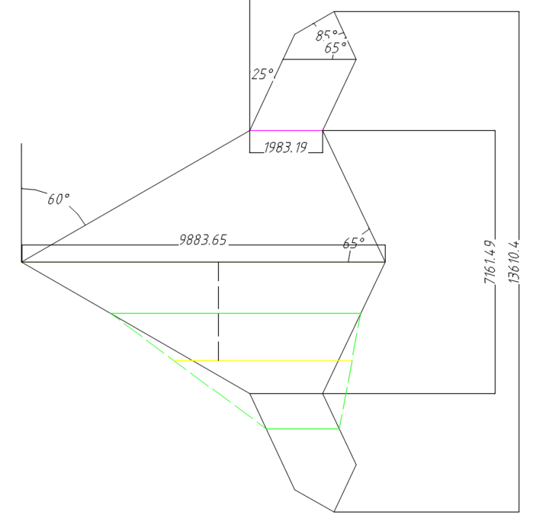
Figure 1. Top view of the wing.
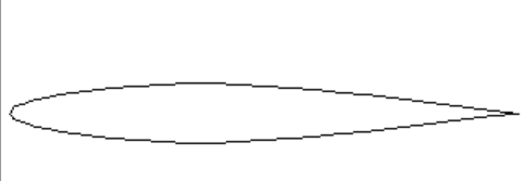
Figure 2. Cross-sectional view of the wing.
3.2. Selection of lifting device, ailerons, flap wings and the control surfaces
3.2.1. Lifting device selection. Five groups of control surfaces to ensure controllability within the flight envelope:
① Inboard elevon, IE
② Outboard elevon, OE
③ Flaperon
④ Leading edge flap, LEF
⑤ All Moving Tip, AMT
The generation of higher lift forces with lower drag is further achieved by increasing the aspect ratio and through the addition of a winglet [2]. Winglet is a small nearly vertical lifting surface that is typically attached to the tip of a wing. The generation of vortices at the wing tip reduces the overall lift generated along the local edges of the wing [3]. Instead of single control surfaces or idealized layouts, a typical aircraft configuration is used with a conventional control surface layout consisting of flaperons and ailerons that is compatible to the current state of the art [4].
3.2.2. Flap parameter selection. Flap parameter selection principle:
There are the following ten principles about the selection of flaps:
① The area of the trailing edge flap is generally 10% - 15% relative to the wing area;
② The best chord length of flap and aileron is generally 20% of the local wing chord length;
③ Flap deflection between 30º and 35º;
④ The chord length of leading edge slats is generally 12% - 16% of the local wing chord length;
⑤ The maximum angle range of the leading edge slat is about 55° ~60°;
⑥ The flap length is limited by the aileron position, and generally cannot exceed 60% of the wing length;
⑦ Flap deflection angle along the airflow generally does not exceed 30º;
⑧ Generally, when taking off and landing, the leading edge is about 10º and the trailing edge is about 30º;
⑨ The front and rear edges are about 5º in cruise state;
⑩ During large maneuvers, the leading edge is 25º ~30º, and the trailing edge is 5º ~10º.
Flap parameter selection
① Root chord length of trailing edge flap: 1.225m;
② Chord length of trailing edge flap tip: 1.483m;
③ Leading edge flap root chord length: 0.702m;
④ Chord length of leading edge flap tip: 0.702m.
3.2.3. Aileron parameter selection. There are the following three principles about the selection of Ailerons:
① The aileron area is generally 5% - 7% relative to the wing area;
② The relative chord length of ailerons is about 20% - 25%;
③general aileron deflection angle δ A not more than 25º.
Aileron parameter selection:
① Aileron area: 2*1.45m2=2.90 m2 (the relative wing area is 5.44%, within the range);
② Chord length of outer aileron wing root: 1.033m;
③ Chord length of wing tip of outboard aileron: 1.033m;
④ Inner aileron: 1.062m*0.728m.
4. Design and analysis of aircraft control system
4.1. Aerodynamic characteristics of wing
4.1.1. Aerodynamic force acting on aircraft wings. (1) Lift and drag. The lift generated by the wing sustains the weight of the aircraft to make flight in the air. Again, from an aerodynamic perspective, the main source of the airplane drag is associated with the wing [5]. The influence of airfoil on the aerodynamic characteristics of aircraft is very obvious. Many parameters of aircraft, such as flight quality, aerodynamic efficiency, cruise speed and so on, are related to airfoil. The lift coefficient of the airfoil needs to reach the lift coefficient corresponding to the maximum lift drag ratio.
The increase of the leading edge radius will affect the increase of the maximum lift coefficient, but the wave resistance at supersonic speed will also increase, so the airfoil with a sharp leading edge is suitable for supersonic aircraft.
The relative thickness of the airfoil has an impact on the aircraft resistance, structural weight, stall characteristics and so on. The relative thickness has little effect on the resistance at subsonic speed, but with the increase of the thickness, the slope of the lift line increases, the resistance increases correspondingly, and the weight of the structure increases. Spanwise lift distribution prediction can be used to predict the structural load, which is important in designing the structural initial sizing and configuration of the wing [6].
The lift and drag of DEP increase in all cases, with the magnitude depending on the angle of attack (AOA) and the relative positions of propellers and wing. When the AOA is less than 16°(stall AOA), the change of lift is not affected by it. By contrast, when the AOA is greater than 16°the L/D (lift-to-drag ratio) increases significantly [7].
The representation of center of pressure for a general family of wing-body configurations (circular cylinder body with no afterbody and plan form made up of straight edges) in a stationary linearized supersonic flow may be considered simply for the limiting cases given by "slender body theory" and "strip theory" [8]. K is also calculated to observe the overall aerodynamic performance [9].
\( Y={C_{y}}\cdot \frac{1}{2}ρ{υ^{2}}\cdot S \) (13)
\( X={C_{x}}\cdot \frac{1}{2}ρ{υ^{2}}\cdot S \) (14)
\( K=\frac{Y}{X}=\frac{{C_{y}}}{{C_{x}}} \) (15)
\( C_{m}^{2}=M/(\frac{1}{2}ρ{υ^{2}}{S_{CR}}) \) (16)
(2) Takeoff speed. The takeoff and landing speed is related to the engine status, takeoff weight, and takeoff angle of attack. Usually, it is also limited by the stall speed of the aircraft and the tail angle, so it is necessary to maintain a certain safety margin. G≈26000kg, F≈5170kg, S≈53.28㎡. When taking off the ground Cy=1.5. Hence, when controlled by stall speed, the aircraft's ground clearance speed is:
\( {υ_{ld}}=1.2{υ_{s}}=1.2×3.6\sqrt[]{\frac{2[G-Fsin{(α+ϕ)}]}{ρS{C_{L,max}}}} \) (17)
Assuming the total weight of the aircraft is 26000kg,
\( {υ_{ld}}=1.2{υ_{s}}=1.2×3.6\sqrt[]{\frac{2[26000×9.8-5170sin{6}0°]}{1.225×53.28×1.5}}=283.57km/h \) (18)
4.1.2. Aerodynamic force of high-speed airflow on the wing. (1) Effect of sweep angle and Wingtip stall. The leading edge sweep angle is the most important plane parameter of the fusion body layout, which plays a decisive role in the longitudinal static stability of the aircraft and the peak distribution of radar cross section. Increasing the leading edge sweep angle is beneficial to high-speed aerodynamic efficiency, drag divergence characteristics and forward stealth, but detrimental to low-speed lift characteristics, torque linearity and stall performance. Small sweep angle is easier to meet the lift and drag performance requirements of takeoff and landing, but it will increase the longitudinal static instability and bring greater difficulty to the longitudinal control.
(2) Influence of aspect ratio Cx. Increasing the chord length of the outer wing can effectively improve the longitudinal static stability, which will bring a large increment of head lowering torque and increase the difficulty of balancing; Secondly, it can effectively weaken the shock wave and suppress the separation, improve the low-speed stall characteristics and high-speed buffeting characteristics, and improve the lift drag ratio at the cruise design point, but the reduction of aspect ratio will reduce the low-speed aerodynamic efficiency. In addition, the increase of the chord length of the outer wing will have an adverse impact on the stealth performance and structural weight. Therefore, on the premise of ensuring the low-speed stall characteristics, the outer wing chord length is selected as small as possible.
(3) Influence of wing plane shape on Cx. The aircraft adopts a double swept back configuration, which can reduce the influence of the leading edge of the wing on the stealth characteristics and effectively block the intake and exhaust ports under the constraints of effectively arranging the intake and exhaust systems. The double sweep configuration can increase the local chord length, improve the loading efficiency, reduce the relative thickness of the section, weaken the upper surface shock wave of the inner wing and improve the aerodynamic efficiency by configuring a larger sweep angle in the inner wing [10].
4.2. Balance of aircraft
4.2.1. Longitudinal balance of aircraft (pitch balance). The longitudinal balance of an aircraft refers to a motion state in which the aircraft moves in a straight line with constant speed in the longitudinal plane and does not rotate around the horizontal axis.
Influencing factors of longitudinal balance:
Generally, the wing produces a downward pitching moment, but when the center of gravity moves backward more and the angle of attack is large, it may produce an upward pitching moment.
In normal flight, the horizontal tail generates negative lift, so the horizontal tail torque is the pitching torque. When the angle of attack is large, the downward bending moment may also occur. The pitching moment produced by the horizontal tail depends on the angle of attack of the wing, the deflection angle of the elevator and the air velocity flowing to the horizontal tail.
The pitching torque can be controlled by increasing or decreasing the throttle, retracting the flaps, retracting the landing gear, and changing the center of gravity.
4.2.2. Heading balance of aircraft (direction balance). The heading balance of an aircraft refers to a state of motion in which the aircraft flies in a straight line at constant speed and does not rotate around the vertical axis.
Influencing factors of heading balance:
The deflection moment produced by the resistance of both wings to the center of gravity. The deflection moment generated by the vertical tail side force on the center of gravity, so the aircraft has no vertical tail, so there will be no such deflection moment. Deflection moment caused by the pull of two or more engines. Steering can be achieved by different thrust of engines on both sides.
4.2.3. Lateral balance of aircraft. The lateral balance of an aircraft refers to a state of motion in which the aircraft flies in a straight line at constant speed and does not rotate around the longitudinal axis.
Influencing factors of lateral balance:
The rolling moment produced by the lift of both wings on the center of gravity. The lateral control torque generated by deflecting ailerons can be used to balance the rolling torque to maintain lateral balance.
4.3. Stability of aircraft
4.3.1. Longitudinal stability of aircraft. Because the fly by wire control system is adopted, the stable flight of the aircraft can be guaranteed with the help of the computer. The focus position is not necessarily behind the center of gravity, so setting the focus position in front of the center becomes a longitudinally unstable aircraft. It can not only improve the maneuverability, but also improve the total lift and reduce the trim resistance.
4.3.2. Heading stability of aircraft. The heading stability torque is generated by the vertical tail when the aircraft skids. The aircraft uses the design of the control surface to compensate for the stability torque.
4.3.3. Lateral stability of aircraft. In the case of the design of the upper anti angle, the angle of attack of the side sliding front wing is larger, and the lift is greater than that of the side sliding rear wing, resulting in the lateral stability moment around the longitudinal axis. In the case of sweepback, the effective partial velocity of the side sliding front wing is large, so the lift is greater than that of the side sliding rear wing, resulting in lateral stability torque.
4.3.4. Coupling of aircraft stability. In order to avoid the flutter, spiral descent and other problems caused by the uncoupled lateral stability and heading stability, the stability of the aircraft in three directions must be coupled as much as possible, and there can be no problem that it is too large or too small somewhere. The stability of aircraft, especially supersonic aircraft, has a certain amount of change, so we should take sufficient measures to adjust the stability to ensure the coupling of stability in three directions.
4.4. Flight performance of aircraft
4.4.1. Thrust required for plane level flight. The speed during level flight is about 660.79m/s, which is converted to Mach number of 1.94Ma, and the P level requirement =46kN.
4.4.2. Maximum level flight speed Vmax and minimum level flight speed Vmin.
\( {υ_{max}}=\sqrt[]{\frac{2{P_{available}}}{{C_{x}}ρS}} \) (19)
\( {υ_{min}}=\sqrt[]{\frac{2G}{ρS{C_{safe}}}} \) (20)
(1) When the aircraft flies horizontally, the thrust P is \( 5170kgf=50.71kN \) , \( Cx=0.0196 \) , the level flight altitude is \( 16km \) , air density is \( ρ=0.1654kg/{m^{3}} \) , \( S=53.28{m^{2}} \)
\( {v_{max}}=\sqrt[]{\frac{2×50710}{0.0196×0.1654×53.28}}=762.18m/s \) (21)
(2) \( {C_{safe}}=1.35 \) , when the angle of attack is \( {8^{∘}} \) , the lift drag ratio has the maximum value, which is the horizontal flight angle of attack, and \( {C_{y}}=0.85 \) ,
\( G=Y={C_{y}}\frac{1}{2}ρ{C^{2}}A=0.85×0.5×0.1654×660.7{9^{2}}×53.28=1635368.30 \) (22)
\( {v_{min}}=\sqrt[]{\frac{2×1635360.30}{0.0196×53.28×1.35}}=524.33m/s \) (23)
4.4.3. Aircraft straightening and ascending performance. (1) fix the rising track angle \( θ \) : \( θ=arcsin\frac{ΔP}{G} \) , depends on the residual thrust.
(2) Straightening rise rate \( {v_{y}} \) : \( {v_{y}}=\frac{ΔPv}{G} \) , depends on the residual thrust.
(3) Static ceiling of aircraft: \( {H_{max}}=18.5km \)
5. Conclusion
In this paper, a swept back symmetrical wing suitable for supersonic reconnaissance aircraft is designed. Its aspect ratio is 3.47, span length is 13.61m, sweep angle is 60°, thrust weight ratio is 0.94, and wing load is 358.4kg/m2. In this paper, the aerodynamic characteristics of the aircraft are analyzed, and on this basis, the inboard electron, outboard electron, flasheron, leading edge flap and all moving tip are designed to ensure the controllability in the flight line, maintain the balance and stability of the aircraft, and make a qualitative analysis of the flight performance of the wing. This paper provides a possibility for the design of supersonic aircraft in the future.
Acknowledgements
I would like to express my gratitude to those who helped me in this paper, especially Professor Eames and Professor Shi, who helped me a lot in the topic selection of this paper. I would also like to thank Professor Yu and Professor Li who gave me a lot of guidance during my college years. I also owe my sincere gratitude to my friends who helped me work out problems during the thesis.
References
[1]. Abdullah Nur Azam; Sulaeman Erwin. Aeroelastic Tailoring of Oscillating Supersonic Wing with External Stores [J]. Applied Mechanics and Materials, 2013.
[2]. Zhonglai Wang, Xiaorong Hu, Yingdong Wu. Energy-efficient wing design for flapping wing micro aerial vehicles [J]. Journal of Mechanical Science and Technology, 2019.
[3]. Z. Siddiqi, J.W. Lee. A computational fluid dynamics investigation of subsonic wing designs for unmanned aerial vehicle application [J]. Proceedings of the Institution of Mechanical Engineers, 2019.
[4]. Binder Simon, Wildschek Andreas, De Breuker Roeland. The interaction between active aeroelastic control and structural tailoring in aeroservoelastic wing design [J]. Aerospace Science and Technology, 2021.
[5]. M. Nazmul Haque; Mohammad Ali; Ismat Ara. Experimental Investigation on the Performance of NACA 4412 Aerofoil with Curved Leading Edge Planform [J]. Procedia Engineering, 2015.
[6]. Faber Y. Silitonga, M. Agoes Moelyadi. Comparative Study of Wing Lift Distribution Analysis for High Altitude Long Endurance (HALE) Unmaned Aerial Vehicle [J]. Journal of Physics: Conference Series, 2018.
[7]. Lei Yao; Wenjie Yang; Yiyong Huang. Aerodynamic performance of distributed electric propulsion with wing interaction [J]. Journal of Zhejiang University-SCIENCE A, 2022.
[8]. G. K. Morikawa; T. F. Coleman. On Supersonic Wing-Body Center of Pressure [J]. Journal of the Aeronautical Sciences, 2012.
[9]. Kale S; Pendharkar E. Effects of wing twist on lift and drag characteristics of blended wing body aircraft [J]. Journal of Physics: Conference Series, 2021.
[10]. Sabri Farhad, Elzaabalawy Assem, Meguid. Aeroelastic behaviour of a flexible morphing wing design for unmanned aerial vehicle [J]. Acta Mechanica, 2022.
Cite this article
Xu,L. (2023). Design of a new sweptback wing for a future supersonic aircraft—Research on lift drag characteristics and aerodynamic analysis. Theoretical and Natural Science,18,1-9.
Data availability
The datasets used and/or analyzed during the current study will be available from the authors upon reasonable request.
Disclaimer/Publisher's Note
The statements, opinions and data contained in all publications are solely those of the individual author(s) and contributor(s) and not of EWA Publishing and/or the editor(s). EWA Publishing and/or the editor(s) disclaim responsibility for any injury to people or property resulting from any ideas, methods, instructions or products referred to in the content.
About volume
Volume title: Proceedings of the 2nd International Conference on Computing Innovation and Applied Physics
© 2024 by the author(s). Licensee EWA Publishing, Oxford, UK. This article is an open access article distributed under the terms and
conditions of the Creative Commons Attribution (CC BY) license. Authors who
publish this series agree to the following terms:
1. Authors retain copyright and grant the series right of first publication with the work simultaneously licensed under a Creative Commons
Attribution License that allows others to share the work with an acknowledgment of the work's authorship and initial publication in this
series.
2. Authors are able to enter into separate, additional contractual arrangements for the non-exclusive distribution of the series's published
version of the work (e.g., post it to an institutional repository or publish it in a book), with an acknowledgment of its initial
publication in this series.
3. Authors are permitted and encouraged to post their work online (e.g., in institutional repositories or on their website) prior to and
during the submission process, as it can lead to productive exchanges, as well as earlier and greater citation of published work (See
Open access policy for details).
References
[1]. Abdullah Nur Azam; Sulaeman Erwin. Aeroelastic Tailoring of Oscillating Supersonic Wing with External Stores [J]. Applied Mechanics and Materials, 2013.
[2]. Zhonglai Wang, Xiaorong Hu, Yingdong Wu. Energy-efficient wing design for flapping wing micro aerial vehicles [J]. Journal of Mechanical Science and Technology, 2019.
[3]. Z. Siddiqi, J.W. Lee. A computational fluid dynamics investigation of subsonic wing designs for unmanned aerial vehicle application [J]. Proceedings of the Institution of Mechanical Engineers, 2019.
[4]. Binder Simon, Wildschek Andreas, De Breuker Roeland. The interaction between active aeroelastic control and structural tailoring in aeroservoelastic wing design [J]. Aerospace Science and Technology, 2021.
[5]. M. Nazmul Haque; Mohammad Ali; Ismat Ara. Experimental Investigation on the Performance of NACA 4412 Aerofoil with Curved Leading Edge Planform [J]. Procedia Engineering, 2015.
[6]. Faber Y. Silitonga, M. Agoes Moelyadi. Comparative Study of Wing Lift Distribution Analysis for High Altitude Long Endurance (HALE) Unmaned Aerial Vehicle [J]. Journal of Physics: Conference Series, 2018.
[7]. Lei Yao; Wenjie Yang; Yiyong Huang. Aerodynamic performance of distributed electric propulsion with wing interaction [J]. Journal of Zhejiang University-SCIENCE A, 2022.
[8]. G. K. Morikawa; T. F. Coleman. On Supersonic Wing-Body Center of Pressure [J]. Journal of the Aeronautical Sciences, 2012.
[9]. Kale S; Pendharkar E. Effects of wing twist on lift and drag characteristics of blended wing body aircraft [J]. Journal of Physics: Conference Series, 2021.
[10]. Sabri Farhad, Elzaabalawy Assem, Meguid. Aeroelastic behaviour of a flexible morphing wing design for unmanned aerial vehicle [J]. Acta Mechanica, 2022.