


1 Introduction
From the early days when man named the stars, mankind has never given up the exploration of the universe. With the majestic development of the world civilization and technology, the countries of the world began to explore towards the stars step by step, and in this process energy became a huge problem. In order to carry out their missions, spacecraft such as satellites need to consume a lot of energy to keep working. The main sources of energy currently used by spacecraft include solar energy, nuclear energy, and the high-pressure gas stored in the launch Pressure vessel high-pressure gases in them, etc. In order to be able to work during the launch phase and during the ground shadow, various batteries are equipped, but within the constraints of limited launch weight, solar cells are the most logical choice in order to meet the long-term operation of high-powered loads. In fact, solar power accounts for the majority of spacecraft in orbit today, reaching 90% of power generation [1]. Solar cells on early spacecraft were set on the surface of the spacecraft and were mainly used on many of the earlier smaller satellites. Such satellites were generally of relatively low power requirements and were spin-stable. Solar panels in this case are poorly utilised and have a maximum power output limit, but such solar panels are relatively simple to deploy and present little or no danger compared to the deployable variety.
With the development of spacecraft, the increase in energy consumption and the demand for greater mass utilisation of satellites, expandable solar panels were developed. This design is also known as a space expandable structure and when the spacecraft is in space we want to make these space expandable results take up as little space as possible and can be released as large as possible once in orbit [2]. Typically, the folding solar panels are distributed on either side of the satellite along the direction of orbital flight and unfolded horizontally when required.
The Miura-ori structure is an origami superstructure [3], which was proposed by the Japanese astrophysicist Koryo Miura at the University of Tokyo. It has a series of excellent properties such as multi-stability and high load-bearing capacity, facilitating a variety of functions such as pre-burial, negative expansion, energy absorption and thermal insulation [4]. The research was originally aimed at solving the problem of folding maps, and was later applied to the antennae and solar panels of satellites. By folding the solar panels, the size of the panels is reduced, thus saving the energy required for the launch of the satellite, and by unfolding a large area after the launch into the intended orbit, the solar panels are able to provide the satellite with the required energy in time.
2 Miura-ori
2.1 Geometry of the Miura-ori
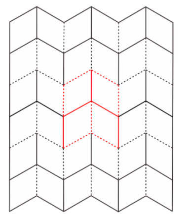
Miura-ori origami is made up of a series of parallelogram units arranged according to certain rules, with the horizontal and vertical folds formed at the joints of each unit, the horizontal folds are straight and the vertical folds are jagged in the fully unfolded state. The angle between the peak and the valley line in the fully unfolded state cannot be a right angle, otherwise the model cannot be unfolded at once by tensioning the diagonal, nor can the angle be too small, otherwise the model will take up too much space in the fully folded state and will not reflect its space-saving advantages [5]. As shown in Figures 1 and 2, the peaks are represented by solid lines, the valleys by dashed lines, and the repeated basic units are marked with red lines. Fold the pattern shown in Fig.1 along the given crease to form the partially folded state in Fig. 1 set \( m \) be the number of peaks in the crease pattern, and \( n \) is the number of valley lines, for the Miura-Ori structure [6], which has four folds per unit structure, i.e.:
\( m+n=4\ \ \ (1) \)
Miura-Ori units also need to meet the requirement of having three peak folds and one valley fold per unit, or three valley folds and one peak fold.
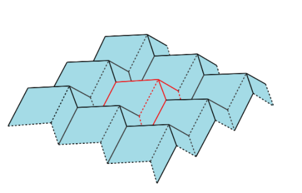
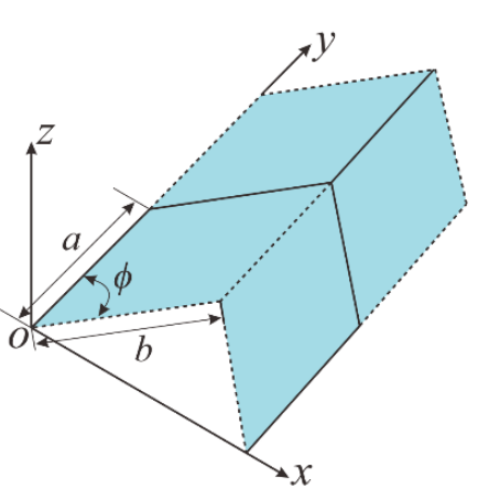
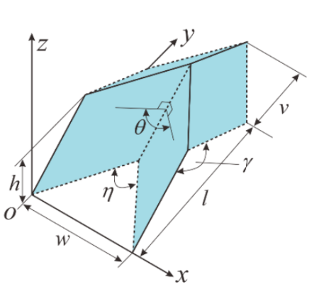
The origami pattern is widely known and used for its excellent and practical mechanical properties such as foldable and expandable planes, single degree of freedom, negative Poisson's ratio and repeatability of the mosaic. The basic unit is shown in Figures 2-3 and 2-4. Figure 2-3 shows the planar state of the basic unit, which is made up of four identical parallelograms stitched together, so its basic shape can be determined by the side length \( a \) , the \( b \) and the angle between \( ϕ∈[0,{90^{∘}}] \) The basic shape can be determined by the lengths of the sides , and the angles. Figure 2-4 shows the semi-folded state of the unit shown in Figure 2-3, at which point its form can be determined by the angle parameter \( η \) , , and \( γ \) , , and \( ϕ \) and the length \( w \) , \( l \) , \( v \) , , and \( h \) are determined, and the following relationships exist for these parameters:
\( (1+cos{η})(1-cos{γ})=4{cos^{2}}{ϕ}\ \ \ (2) \)
\( cos{γ}=\frac{{sin^{2}}{ϕ{cos^{2}}{(\frac{θ}{2})}}-{cos^{2}}{ϕ}}{{sin^{2}}{ϕ{cos^{2}}{(\frac{θ}{2})}}+{cos^{2}}{ϕ}}\ \ \ (3) \)
\( Cos{η}={sin^{2}}{ϕ{cos^{2}}{(\frac{θ}{2})}}+{cos^{2}}{ϕ}\ \ \ (4) \)
\( w=2bsin{(\frac{η}{2})}\ \ \ (5) \)
\( l=2asin{(\frac{γ}{2})}\ \ \ (6) \)
\( v=bcos{(\frac{η}{2})}\ \ \ (7) \)
\( h=acos{(\frac{γ}{2})}\ \ \ (8) \)
It follows that seven mutually independent equations are established between the ten Miura-ori parameters [7], in addition to which the number of peak and valley folds is added \( m \) and \( n \) two parameters make up the Miura-ori. Where the basic shape of the Miura-oir is determined, i.e. the side lengths a, b and the angle of the parallelogram forming the Miura-ori \( θ \) The coefficients of the peak and valley lines are also independent of the folding state and remain constant. The remaining seven parameters are collectively referred to as folding variables because they change when the folding state of the same folding unit is changed. So the seven equations in the unknown, only need to know any one of the remaining parameters can be found out, that is, its space folding form can be by \( θ∈[{0^{∘}},{180^{∘}}] \) , \( η∈[{0^{∘}},2ϕ] \) , and \( γ∈[{180^{∘}}-2ϕ,180] \) , and \( w \) , and \( l \) , and \( v \) , and \( h \) obtained by calculating any one of them, which also directly confirms the previous finding that Miura-ori has a single degree of freedom. Here, we uniformly use the folded dihedral angle \( θ \) as the basis for calculating the remaining parameters when \( θ \) = \( {0^{∘}} \) when the Miura unit is fully collapsed, and when \( θ \) = \( {180^{∘}} \) The Miura-ori plate has identical Miura cells, so that its geometric properties are essentially determined by the Miura cells and are consistent throughout.
|
|
Figure. 1. Miura-ori origami plane state. | Figure.2.Miura-ori origami partially folded state. |
|
|
Figure 3. Miura-ori unit plane state. | Figure 4. Miura-ori unit partially collapsed. |
2.2 Flat foldable condition
For rigid origami, the question of whether an origami pattern can be folded flat has always been a major concern. Planar foldability is interpreted as being both unfoldable into a plane and foldable into a plane. This study is an important branch of mechanics [8] and requires the determination of vertex positions, types of folds, number and distribution of folds, etc. The Miura-ori unit is relatively straightforward, being a simple origami pattern containing only one origin (i.e. all folds compared to the same point) and for which it has only four folds, and its conditions are correspondingly simple.
In traditional origami, we start with a flat sheet of paper, the structure of which contains the spreading condition, and the Miura-Ori unit structure consists of four quadrilateral faces along the crease. The spreading condition constrains the four quads to be in the same plane, and the angle of the four folds around the vertices in the Miura-Ori unitary structure satisfies.
\( {α_{1}}+{β_{1}}+{α_{2}}+{β_{2}}=2π\ \ \ (9) \)
Maekawa's theorem 40: The number of valley lines at the same vertex is denoted M, V respectively, and the difference between the two must only be \( ±2 \) , which can be expressed as [9]:
\( m-n=±2\ \ \ (10) \)
As mentioned above, for the Miura-Ori structure, each cell has four folds and each cell has either three peaks and one valley, or three valleys and one peak.
For zero-thickness origami structures, the flat fold condition means that all planes of the structure are coplanar in the fully folded state.
Kawasaki presented a flat-folding theorem for single-vertex multifold origami. For the four-fold Miura-Ori, it is necessary to Meet [10]:
\( {α_{1}}+{β_{1}}={α_{2}}+{β_{2}}={180^{∘}} {α_{1}}+{α_{2}}≥{β_{1}}+{β_{2}}\ \ \ (11) \)
2.3 The kinematics of Miura-ori
The single vertex Miura-ori structure is extended as shown in Figure 5. The equivalent linkage structure is shown in Figure 6, with joints of the same subscript aligned and combined to give a combination of four spherical 4R mechanisms. Joints a1 and a2 in linkage A overlap with joint b1 in linkage B and joint d2 in linkage D respectively. Joints c3 and c4 in linkage C coincide with joint d3 in linkage D and joint b4 in linkage B respectively. Thus, the joints 12 (or 41) of linkage A and 41 (or 12) of linkage B have the same angle of rotation, and \( θ_{1}^{A}=θ_{1}^{B} \) and, by the same token, we have \( θ_{2}^{A}=θ_{2}^{D}, θ_{4}^{B}=θ_{4}^{C} \) and \( θ_{3}^{C}=θ_{3}^{D} \) .
|
|
Figure 5.The single vertex miura-ori structure. | Figure 6. The equivalent linkage structure. |

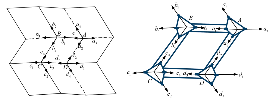
Since the thick plate model has rotational symmetry, only the common folds a1 (b1), a2 (d2 ), b4 (c4 ) and c3 (d3 ) need to be transformed at their respective nodes to obtain the transformation matrix and closure relations as follows:
\( \begin{array}{c} { ^{B}}{T_{A}}=Rot(Z_{1}^{A},π-θ_{4}^{A})Trans(0,0,{l_{AB}})Rot(X_{1}^{B},π) \\ =[\begin{matrix}-cos{θ_{4}^{A}} & -sin{θ_{4}^{A}} & 0 & 0 \\ sin{θ_{4}^{A}} & -cos{θ_{4}^{A}} & 0 & 0 \\ 0 & 0 & 1 & {l_{AB}} \\ 0 & 0 & 0 & 1 \\ \end{matrix}][\begin{matrix}1 & 0 & 0 & 0 \\ 0 & -1 & 0 & 0 \\ 0 & 0 & -1 & 0 \\ 0 & 0 & 0 & 1 \\ \end{matrix}] \\ =[\begin{matrix}cos{θ_{4}^{A}} & sin{θ_{4}^{A}} & 0 & 0 \\ -sin{θ_{4}^{A}} & cos{θ_{4}^{A}} & 0 & 0 \\ 0 & 0 & -1 & {l_{AB}} \\ 0 & 0 & 0 & 1 \\ \end{matrix}] \end{array} \ \ \ (12) \)
\( { ^{B}}T_{A}^{B2}{T_{B1}}{ ^{B3}}{T_{B2}}{ ^{B4}}{T_{B3}}{ ^{C}}{T_{B}}{ ^{C1}}{T_{C4}}{ ^{C2}}{T_{C1}}{ ^{C3}}{T_{C2}}{ ^{D}}{T_{C}}{ ^{D4}}{T_{D3}}{ ^{D1}}{T_{D4}}{ ^{D2}}{T_{D1}}{ ^{A}}{T_{D}}{ ^{A3}}{T_{A2}}{ ^{A4}}{T_{A3}}{ ^{A1}}{T_{A4}}=I \)
(1)
\( {T_{A1}}=[\begin{matrix}cos{{θ_{1}}} & -sin{{θ_{1}}} & 0 & 0 \\ cos{{α_{1,2}}sin{{θ_{1}}}} & cos{{α_{1,2}}cos{{θ_{1}}}} & -sin{{α_{1,2}}} & 0 \\ sin{{α_{1,2}}sin{{θ_{1}}}} & sin{{α_{1,2}}cos{{θ_{1}}}} & cos{{α_{1,2}}} & 0 \\ 0 & 0 & 0 & 1 \\ \end{matrix}]\ \ \ (14) \)
\( {T_{B1}}{ ^{B3}}{T_{B2}}{ ^{B4}}{T_{B3}}={ ^{B1}}{T_{B4}}{ ^{-1}}\ \ \ (15) \)
\( { ^{C1}}{T_{C4}}{ ^{C2}}{T_{C1}}{ ^{C3}}{T_{C2}}={ ^{C4}}{T_{C3}}{ ^{-1}}\ \ \ (16) \)
\( { ^{D4}}{T_{D3}}{ ^{D1}}{T_{D4}}{ ^{D2}}{T_{D1}}={ ^{D3}}{T_{D2}}{ ^{-1}}\ \ \ (17) \)
\( { ^{A3}}{T_{A2}}{ ^{A4}}{T_{A3}}{ ^{A1}}{T_{A4}}={ ^{A2}}{T_{A1}}{ ^{-1}}\ \ \ (18) \)
All coordinate systems form a closed-loop system, and the above equation gives a closed-loop equation for all transformation matrices in Eq.
\( { ^{B}}{T_{A}}{ ^{B1}}{T_{B4}}{ ^{-1C}}{T_{B}}{ ^{C4}}{T_{C3}}{ ^{-1D}}{T_{C}}{ ^{D3}}{T_{D2}}{ ^{-1A}}{T_{D}}{ ^{A2}}{T_{A1}}{ ^{-1}}=I\ \ \ (20) \)
The left-hand side of the above equation is a matrix containing only the variables and the right-hand side of the equation is a unit matrix \( I \) ; by the equality of the elements corresponding to the two ends of the equation, a system of equations equal in number to the number of folds can be obtained. Using \( {θ_{1}} \) as the input angle, the range of variation is \( {0^{∘}}∼{180^{∘}} \) , the curve of change of the fold angle with respect to the input angle can be obtained.
|
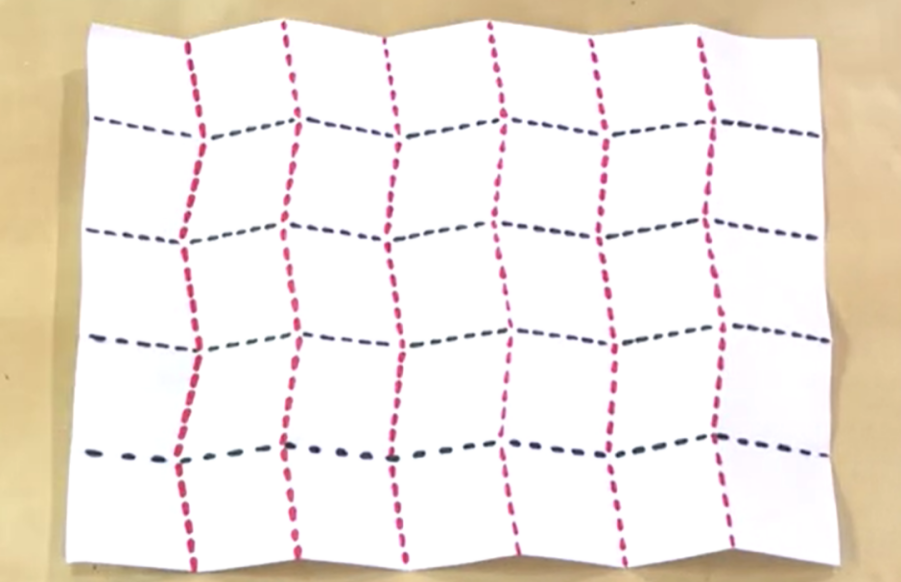
Figure 7. Homemade miura-ori model. |
3 Conclusion
This paper analyses in detail the geometric design and motion analysis of the Miura-ori structure. Firstly, the geometric structure of the basic folding unit is established, seven equations are obtained for the twelve folding variables and the positions of the vertices of the basic folding unit are determined. Based on the basic folding unit, Miura-ori is equated to a simple 4R mechanism or a combination of four spherical 4R mechanisms, and a coordinate system is established by applying the D-H parameter method. \( {0^{∘}}∼{180^{∘}} \) The Miura-ori is shown to be fully foldable with symmetric motion. Finally the solid model is folded.
Miura-ori is characterised by its simple geometry, good mechanical properties and single degree of freedom, as well as a series of excellent properties such as multi-stability and high load-bearing capacity, but it also has some minor drawbacks: firstly, the folding and unfolding process is relatively complex, and the second folding requirement is also high, and the angle must not be too small, otherwise the model will take up too much space in the fully folded state and will not be able to Otherwise, the model would take up too much space in its fully folded state and would not be able to demonstrate its space-saving advantages. The performance of the structure itself will certainly be affected by the surrounding environment and boundary conditions, and Miura-ori still requires considerable consideration in practical applications.
References
[1]. Li QJ, Deng ZC. Research progress on space solar power plants and their dynamics and control[J]. Journal of Harbin Institute of Technology,2018,50(10):1-19.
[2]. Yi Kechu, Li Yi, Sun Chenhua, Nan Chunguo. Recent development and prospect of satellite communication[J]. Journal of Communication,2015,36(06):161-176.
[3]. Cai J, Feng J Analysis of motion process based on origami model column surface shell structure[C]. Proceedings of the 14th Academic Conference on Space Structures,2012:165-170.
[4]. Han Yunlong. Design and analysis of folding plate and shell structure [D]. Jiangsu:Southeast University,2011.
[5]. Abel Z, Cantarella J, Demaine E D, et al. Rigid origami vertices: Conditions and forcing sets[J]. Journal of Computational Geometry, 2016, Vol 7: 171-184 Pages
[6]. Chen Yao, Feng Jian. Symmetric Deployable Structures: Form-finding, Folding and Application Research.Nanjing: Southeast University Press, 2015
[7]. Justin J. Towards a mathematical theory of origami [C]. Origami Science andArt : Proceedings of Second Intemational Meeting of Origami Science andScientific Origami.Otsu. Japan.1994:15-29.
[8]. Wang Zhe. Structural design of Miura origami-based deployable solar concentrator and its concentrating characteristics[D].
[9]. Kawasaki T. On the relation between mountain-creases and valley-creases of a flatorigami [C].Proceedings of First International Meeting of Origami Proceedings of First International Meeting of Origami Science andTechnology, Ferrara, Italy. 1989: 229-237.
[10]. Liu Rongq iang, Shi Chuang,GuoHongwei,et al. Review of space deployable antenna mechanisms.
Cite this article
Fan,R. (2023). Folding solar panels in space: Miura-ori and its kinematic behavior. Theoretical and Natural Science,18,246-251.
Data availability
The datasets used and/or analyzed during the current study will be available from the authors upon reasonable request.
Disclaimer/Publisher's Note
The statements, opinions and data contained in all publications are solely those of the individual author(s) and contributor(s) and not of EWA Publishing and/or the editor(s). EWA Publishing and/or the editor(s) disclaim responsibility for any injury to people or property resulting from any ideas, methods, instructions or products referred to in the content.
About volume
Volume title: Proceedings of the 2nd International Conference on Computing Innovation and Applied Physics
© 2024 by the author(s). Licensee EWA Publishing, Oxford, UK. This article is an open access article distributed under the terms and
conditions of the Creative Commons Attribution (CC BY) license. Authors who
publish this series agree to the following terms:
1. Authors retain copyright and grant the series right of first publication with the work simultaneously licensed under a Creative Commons
Attribution License that allows others to share the work with an acknowledgment of the work's authorship and initial publication in this
series.
2. Authors are able to enter into separate, additional contractual arrangements for the non-exclusive distribution of the series's published
version of the work (e.g., post it to an institutional repository or publish it in a book), with an acknowledgment of its initial
publication in this series.
3. Authors are permitted and encouraged to post their work online (e.g., in institutional repositories or on their website) prior to and
during the submission process, as it can lead to productive exchanges, as well as earlier and greater citation of published work (See
Open access policy for details).
References
[1]. Li QJ, Deng ZC. Research progress on space solar power plants and their dynamics and control[J]. Journal of Harbin Institute of Technology,2018,50(10):1-19.
[2]. Yi Kechu, Li Yi, Sun Chenhua, Nan Chunguo. Recent development and prospect of satellite communication[J]. Journal of Communication,2015,36(06):161-176.
[3]. Cai J, Feng J Analysis of motion process based on origami model column surface shell structure[C]. Proceedings of the 14th Academic Conference on Space Structures,2012:165-170.
[4]. Han Yunlong. Design and analysis of folding plate and shell structure [D]. Jiangsu:Southeast University,2011.
[5]. Abel Z, Cantarella J, Demaine E D, et al. Rigid origami vertices: Conditions and forcing sets[J]. Journal of Computational Geometry, 2016, Vol 7: 171-184 Pages
[6]. Chen Yao, Feng Jian. Symmetric Deployable Structures: Form-finding, Folding and Application Research.Nanjing: Southeast University Press, 2015
[7]. Justin J. Towards a mathematical theory of origami [C]. Origami Science andArt : Proceedings of Second Intemational Meeting of Origami Science andScientific Origami.Otsu. Japan.1994:15-29.
[8]. Wang Zhe. Structural design of Miura origami-based deployable solar concentrator and its concentrating characteristics[D].
[9]. Kawasaki T. On the relation between mountain-creases and valley-creases of a flatorigami [C].Proceedings of First International Meeting of Origami Proceedings of First International Meeting of Origami Science andTechnology, Ferrara, Italy. 1989: 229-237.
[10]. Liu Rongq iang, Shi Chuang,GuoHongwei,et al. Review of space deployable antenna mechanisms.