1. Introduction
Flexible manipulators have been increasingly applied in fields such as aerospace, construction machinery, and medical surgery due to their unique performance advantages [1]. Compared with traditional rigid manipulators, flexible manipulators exhibit notable features such as lightweight structure [2], large working radius, high mobility, high payload-to-weight ratio [3], and low energy consumption. These characteristics make them particularly competitive in tasks that involve complex environments and demand high precision. However, during motion, flexible manipulators inevitably generate elastic vibrations, which significantly impair the positioning accuracy of the end-effector, thereby limiting their applicability in high-precision operations.
In practical applications, the vibration coupling effects among multiple joints of flexible manipulators further increase the complexity of dynamic modeling. Establishing an accurate dynamic model is fundamental to achieving effective control. However, current dynamic modeling methods face significant computational burdens and complexity when dealing with multi-degree-of-freedom flexible manipulators. Moreover, the ability to accurately and promptly measure the vibration states of flexible manipulators is critical for achieving precise control. Yet, existing measurement technologies still fall short in terms of both accuracy and real-time performance. Therefore, the development of efficient measurement techniques and the design of highly robust control algorithms are of great theoretical significance and practical engineering value for enhancing vibration suppression and precise positioning control of flexible manipulators.
2. Modeling of the flexible-link manipulator
2.1. Coordinate system establishment and parameter definition
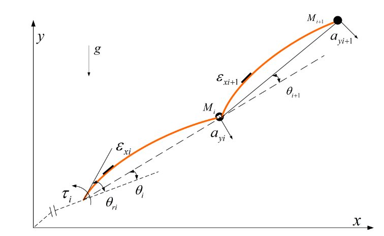
This study focuses on a two-degree-of-freedom flexible manipulator to establish coordinate systems and define the relevant parameters. A fixed coordinate system O is introduced, along with moving coordinate systems O1 and O2, which are rigidly attached to Link 1 and Link 2, respectively. The parameters are defined as follows: θ1nand θ2: joint angles; l1 and l2: lengths of Link 1 and Link 2; m1 and m2: masses of Link 1 and Link 2; J1 and J2: moments of inertia of Joint 1 and Joint 2; ρ1 and ρ2: mass densities per unit volume of Link 1 and Link 2; A1 and A2: cross-sectional areas of Link 1 and Link 2.
E1 and E2: elastic moduli of Link 1 and Link 2; I1 and I2: area moments of inertia of Link 1 and Link 2. The physical meanings of these parameters are illustrated in Figure 1.
2.2. Dynamic modeling
The dynamic model is established using the Lagrangian method, and the resulting dynamic equations are linearized. The dynamic model of the flexible manipulator is thus obtained as follows [4]:
where M is the generalized mass matrix, K is the generalized stiffness matrix, and C represents the system damping, which can be modeled using Rayleigh damping:
α0and α1 are the proportional coefficients of Rayleigh damping.
2.3. Kinematic modeling
Considering that the primary objective of this report is vibration suppression of the flexible manipulator system, the kinematic modeling focuses mainly on the end-effector kinematics. The displacement at the end of the manipulator is primarily caused by the flexible deformation of the links [5], and can be expressed as:
qi(t) is the generalized coordinate of the i-th mode, ϕi(x) is the mode shape function of the i-th mode, and n is the number of modes considered. The time response of the modal coordinate qi(t) can be obtained by solving the dynamic equations. Assuming the system is subjected to an excitation at the initial time, the time response of the modal coordinate can be expressed as:
Ai and Bi are determined by the initial state x0 and the mode shape function ϕi(x), and ωi is the natural frequency of the i-th mode.
3. Controller design
Based on the kinematic and dynamic models of the flexible manipulator established in the previous section, this section focuses on addressing the control design challenges caused by the system’s multivariable strong coupling characteristics and nonlinear dynamic features. Following the principle of progressive comparative design, three control strategies are designed sequentially: PID, LQR, Sliding Mode Control (SMC), and Fast Terminal Sliding Mode Control (FTSMC). Their complexity follows the progressive design principle of "linear compensation → robustness enhancement → fast finite-time convergence" [6].
3.1. Control objective
For the vibration suppression requirements of the dual flexible arms, the practical control objective is that the end-effector displacement of the manipulator along the y-direction equals zero (the radial displacement of the Bernoulli beam in the application scenario can be neglected) [7]. To facilitate controller design, the control objective is further refined as ensuring the vibration variables qi converge to zero.
3.2. PID
In response to the vibration suppression requirements of the dual flexible manipulator system, this subsection develops a solution based on classical PID control [8]. The core element of the control architecture is clarified first: the controlled variable is the end-effector vibration displacement, whose dynamic characteristics can be modeled as [9]:
The actuators selected are the drive motors of Joint 1 and Joint 2, producing output torques τ1 and τ2. To verify their disturbance rejection performance (i.e., vibration suppression capability), a disturbance is designed as an initial vibration caused by a 10 N external force applied at the end-effector. The control system is required to satisfy the following specifications: overshoot less than 5%, settling time less than 2 seconds, and steady-state error approaching zero.
Based on the principle of structural decoupling, a decentralized control strategy is employed to design independent controllers for the two joints. The controller for Joint 1 only handles the state variables and their derivatives related to Joint 1, while the controller for Joint 2 independently processes the state variables associated with Joint 2. The control laws for the two joints are expressed respectively as follows [10]:
Proportional term Kp: provides a “stiffness” restoring force proportional to the vibration displacement; Derivative term Kd: introduces virtual damping to suppress vibration velocity; Integral term Ki: eliminates steady-state error (such as static deformation caused by gravity).
3.3. LQR-based controller design
3.3.1. System model transformation
Assume that the dynamic model of the manipulator can be represented as a linear time-invariant system:
Where x(t) is the system state vector, u(t) is the control input vector, A is the state transition matrix, and B is the input matrix.
3.3.2. Cost function
The objective of LQR is to minimize the following quadratic cost function:
Q is the state weighting matrix, and R is the control input weighting matrix, which are usually chosen as diagonal matrices [10], with Q≥0,R>0.
3.3.3. Controller design
According to LQR theory, the optimal control input u(t) can be expressed as [11]:
Where K is the feedback gain matrix, which can be obtained by solving the Riccati equation:
Solve the above Riccati equation to obtain matrix P, and then compute the gain matrix K:
Typically, Q is chosen as a diagonal matrix, with diagonal elements adjusted according to the importance of the state variables [12]. R is selected as a diagonal matrix, with diagonal elements adjusted based on the cost of control inputs.
3.4. Classical sliding mode control design
3.4.1. Sliding surface definition
With the objective of attenuating elastic modes, the sliding surface is designed as:
Where the sliding surface s1 is a linear combination that relates the elastic modal displacement qi (describing the bending deformation of the link) and its velocity q˙i (describing the rate of change of bending deformation). The parameter λi>0 determines the convergence rate of the sliding surface [13]. When si=0, the system is on the sliding surface, and the following holds:
Elastic vibrations decay exponentially. A larger λi accelerates the decay but may increase the demand for control input. The physical objective of sliding mode control is to drive the system states (elastic vibration modes) onto the sliding surface, i.e., si=0, by means of control torques, thereby suppressing the vibrations [14].
3.4.2. Control law derivation
By decoupling the dynamic equations, we obtain:
3.5. Fast terminal sliding mode control design
To avoid singularity issues in the manipulator system and ensure global finite-time convergence of the system [15], a product form of the sign function and absolute value power is introduced to prevent the emergence of complex terms, thereby overcoming the singularity problem. Accordingly, a nonsingular fast terminal sliding surface function is designed as:
It is evident that when the manipulator system tracking error is near the equilibrium point, the higher-order terms in the sliding surface can be neglected, and the sliding mode system exhibits a relatively fast convergence speed; when the tracking error is far from the equilibrium point, the convergence time of the manipulator system is mainly dominated by the higher-order terms in the derivative of the nonsingular fast terminal sliding surface, and the state variables still have a large convergence rate. These two parts together ensure that the manipulator system can achieve rapid and accurate global convergence within a short time. Based on this, the classical sliding mode controller can be improved, and the fast terminal sliding mode controller is designed as follows:
Where −b1 is used to map the state-space variables to the input space,fi is the feedforward component used to compensate for the nonlinear terms in the system; λpiq+λviq˙i is a typical proportional-integral (PI) component, serving as the nominal part of the feedback control; ηisign(σi)+kisi is the robust sliding mode term, ensuring the system operates on the sliding surface and resists disturbances.
4. Simulation of end-effector vibration suppression and positioning control of flexible manipulator
The linearized dynamic model of the two-degree-of-freedom flexible manipulator can be expressed as:
The specific parameter values used in the simulation experiments are listed in Table 1.
|
flexible arm |
lengthL/m |
Quality m/Kg |
Moment of inertia of the rod cross-section I/m4 |
Elastic modulus E/Pa |
Lumped mass at the joint M/Kg |
|
L1 |
0.475 |
0.374 |
16×10-11 |
2.06×10¹¹ |
2.94 |
|
L2 |
0.435 |
0.29 |
6.75×10⁻¹¹ |
2.06×10¹¹ |
1.343 |
4.1. PID controller
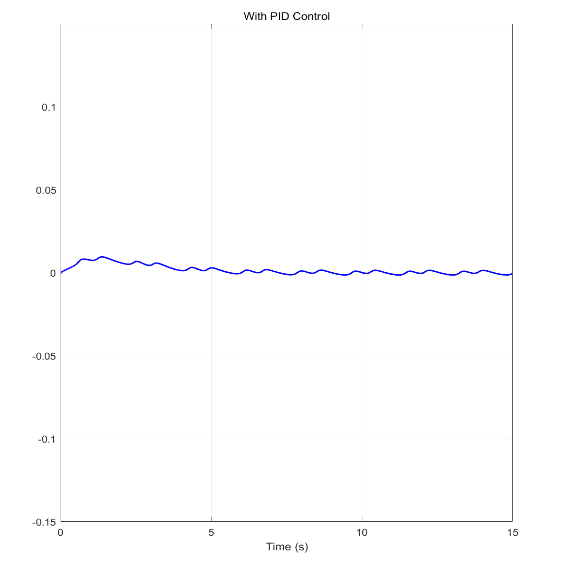
The PID controller achieves a balance between dynamic response speed and stability, with an overshoot of 4.6% and a settling time of 1.374 seconds, making it suitable for scenarios with relatively accurate models, as shown in Figure 2.
4.2. LQR controller
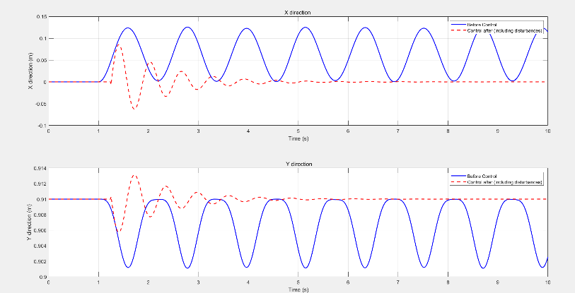
As shown in Figure 3, under LQR control, the flexible manipulator ultimately reaches a stable state, achieving precise end-positioning. The overshoot is 5.7%, and the settling time is 3.426 seconds. The LQR controller is energy-optimal when the model is accurate, but its dynamic performance (overshoot and settling time) is relatively poor.
4.3. Sliding mode control
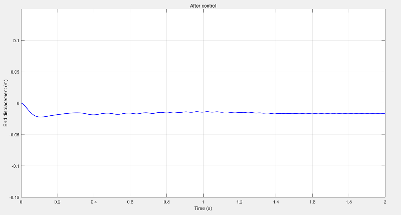
The sliding mode controller exhibits strong robustness and zero overshoot, but has a slower rise time and requires chattering suppression, as shown in Figure 4.
4.4. Fast terminal sliding mode control
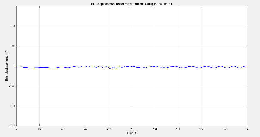
The fast terminal sliding mode controller exhibits strong robustness and zero overshoot, with a faster rise time but requires chattering suppression, as shown in Figure 5.
5. Research summary
In the end-position control of flexible manipulators, the four typical methods each have their applicable scenarios and room for improvement: PID control, with its simple structure and ease of engineering implementation, is suitable for simple industrial scenarios such as agricultural picking that require moderate precision. However, it exhibits weak high-frequency vibration suppression and depends on empirical parameter tuning. Future improvements may be achieved by integrating fuzzy control and neural networks for adaptive optimization. LQR control performs excellently in laboratory environments with accurately known models or in multivariable coupled systems, but it is limited by strong model dependency and high computational complexity. Its practicality needs enhancement through robust control, model order reduction, and nonlinear control techniques. Sliding Mode Control (SMC), due to its strong disturbance rejection and robustness, is widely applied in harsh environments with large load variations and strong uncertainties. However, chattering issues and the deceleration of convergence speed in later stages restrict its performance, which can be improved via higher-order sliding mode design and adaptive laws. Fast Terminal Sliding Mode Control (FTSMC) meets the stringent demands of rapid and precise positioning with finite-time convergence, as required in medical microsurgery. Nevertheless, it faces local convergence limitations and singularity risks, necessitating development toward global nonsingular sliding modes and multimodal hierarchical control. Currently, flexible manipulator control faces common challenges including the complexity of rigid-flexible coupled modeling, multi-objective optimization conflicts, and hardware computational bottlenecks. Future trends focus on intelligent algorithms (e.g., integration of deep learning and control), distributed cooperative control, integration of novel sensors and actuators, and innovative control mechanisms inspired by biomechanics, to promote a deep integration of theoretical research and engineering applications.
References
[1]. Aoustin, Y., Chevallereau, C., Glumineau, A., & Moog, C. H. (1994). Experimental results for the end-effector control of a single flexible robotic arm. IEEE Transactions on Control Systems Technology, 2(4), 371–381.
[2]. Asada, H., Ma, Z.-D., & Tokumaru, H. (1990). Inverse dynamics of flexible robot arms: Modeling and computation for trajectory control. [Unpublished manuscript].
[3]. de Queiroz, M. S., Dawson, D. M., Agarwal, M., & Zhang, F. (2002). Adaptive online AR boundary control of a flexible link robot arm. IEEE Transactions on Robotics and Automation, 15(4), 779–787.
[4]. Etxebarria, V., Sanz, A., & Lizarraga, I. (2005). Control of a lightweight flexible robotic arm using sliding modes. International Journal of Advanced Robotic Systems, 2(2), 11.
[5]. Hillsley, K. L., & Yurkovich, S. (1993). Vibration control of a two-link flexible robot arm. Dynamics and Control, 3(3), 261–280.
[6]. Hu, F. L., & Ulsoy, A. G. (1994). Dynamic modeling of constrained flexible robot arms for controller design. [Unpublished manuscript].
[7]. Jamali, A., & Mat Darus, I. Z. (2020). Intelligent evolutionary controller for flexible robotic arm. Journal of Physics: Conference Series, 1500, 012020. https: //doi.org/10.1088/1742-6596/1500/1/012020
[8]. Kanoh, H., Tzafestas, S., Lee, H. G., & Kalat, J. (1986). Modelling and control of flexible robot arms. In Proceedings of the 25th IEEE Conference on Decision and Control (pp. 1866–1870). IEEE.
[9]. Luo, Z.-H. (1993). Direct strain feedback control of flexible robot arms: New theoretical and experimental results. IEEE Transactions on Automatic Control, 38(11), 1610–1622.
[10]. Luo, Z.-H., Kitamura, N., & Guo, B.-Z. (1995). Shear force feedback control of flexible robot arms. IEEE Transactions on Robotics and Automation, 11(5), 760–765.
[11]. Sakawa, Y., Matsuno, F., & Fukushima, S. (1985). Modeling and feedback control of a flexible arm. Journal of Robotic Systems, 2(4), 453–472.
[12]. Sooraksa, P., & Chen, G. (1998). Mathematical modeling and fuzzy control of a flexible-link robot arm. Mathematical and Computer Modelling, 27(6), 73–93.
[13]. Uchiyama, M., et al. (1994). Contribution to inverse kinematics of flexible robot arms.
[14]. JSME International Journal. Series C, Dynamics, Control, Robotics, Design and Manufacturing, 37(4), 755–764.
[15]. Wang, P. K.-C., & Wei, J.-D. (1987). Vibrations in a moving flexible robot arm. Journal of Sound and Vibration, 116(1), 149–160.
[16]. Wells, R. L., Schueller, J. K., & Tlusty, J. (1990). Feedforward and feedback control of a flexible robotic arm. IEEE Control Systems Magazine, 10(1), 9–15.
Cite this article
Lu,Z.;Lei,C. (2025). Precise End-Position Control of Flexible Manipulators. Theoretical and Natural Science,120,60-69.
Data availability
The datasets used and/or analyzed during the current study will be available from the authors upon reasonable request.
Disclaimer/Publisher's Note
The statements, opinions and data contained in all publications are solely those of the individual author(s) and contributor(s) and not of EWA Publishing and/or the editor(s). EWA Publishing and/or the editor(s) disclaim responsibility for any injury to people or property resulting from any ideas, methods, instructions or products referred to in the content.
About volume
Volume title: Proceedings of CONF-APMM 2025 Symposium: Controlling Robotic Manipulator Using PWM Signals with Microcontrollers
© 2024 by the author(s). Licensee EWA Publishing, Oxford, UK. This article is an open access article distributed under the terms and
conditions of the Creative Commons Attribution (CC BY) license. Authors who
publish this series agree to the following terms:
1. Authors retain copyright and grant the series right of first publication with the work simultaneously licensed under a Creative Commons
Attribution License that allows others to share the work with an acknowledgment of the work's authorship and initial publication in this
series.
2. Authors are able to enter into separate, additional contractual arrangements for the non-exclusive distribution of the series's published
version of the work (e.g., post it to an institutional repository or publish it in a book), with an acknowledgment of its initial
publication in this series.
3. Authors are permitted and encouraged to post their work online (e.g., in institutional repositories or on their website) prior to and
during the submission process, as it can lead to productive exchanges, as well as earlier and greater citation of published work (See
Open access policy for details).
References
[1]. Aoustin, Y., Chevallereau, C., Glumineau, A., & Moog, C. H. (1994). Experimental results for the end-effector control of a single flexible robotic arm. IEEE Transactions on Control Systems Technology, 2(4), 371–381.
[2]. Asada, H., Ma, Z.-D., & Tokumaru, H. (1990). Inverse dynamics of flexible robot arms: Modeling and computation for trajectory control. [Unpublished manuscript].
[3]. de Queiroz, M. S., Dawson, D. M., Agarwal, M., & Zhang, F. (2002). Adaptive online AR boundary control of a flexible link robot arm. IEEE Transactions on Robotics and Automation, 15(4), 779–787.
[4]. Etxebarria, V., Sanz, A., & Lizarraga, I. (2005). Control of a lightweight flexible robotic arm using sliding modes. International Journal of Advanced Robotic Systems, 2(2), 11.
[5]. Hillsley, K. L., & Yurkovich, S. (1993). Vibration control of a two-link flexible robot arm. Dynamics and Control, 3(3), 261–280.
[6]. Hu, F. L., & Ulsoy, A. G. (1994). Dynamic modeling of constrained flexible robot arms for controller design. [Unpublished manuscript].
[7]. Jamali, A., & Mat Darus, I. Z. (2020). Intelligent evolutionary controller for flexible robotic arm. Journal of Physics: Conference Series, 1500, 012020. https: //doi.org/10.1088/1742-6596/1500/1/012020
[8]. Kanoh, H., Tzafestas, S., Lee, H. G., & Kalat, J. (1986). Modelling and control of flexible robot arms. In Proceedings of the 25th IEEE Conference on Decision and Control (pp. 1866–1870). IEEE.
[9]. Luo, Z.-H. (1993). Direct strain feedback control of flexible robot arms: New theoretical and experimental results. IEEE Transactions on Automatic Control, 38(11), 1610–1622.
[10]. Luo, Z.-H., Kitamura, N., & Guo, B.-Z. (1995). Shear force feedback control of flexible robot arms. IEEE Transactions on Robotics and Automation, 11(5), 760–765.
[11]. Sakawa, Y., Matsuno, F., & Fukushima, S. (1985). Modeling and feedback control of a flexible arm. Journal of Robotic Systems, 2(4), 453–472.
[12]. Sooraksa, P., & Chen, G. (1998). Mathematical modeling and fuzzy control of a flexible-link robot arm. Mathematical and Computer Modelling, 27(6), 73–93.
[13]. Uchiyama, M., et al. (1994). Contribution to inverse kinematics of flexible robot arms.
[14]. JSME International Journal. Series C, Dynamics, Control, Robotics, Design and Manufacturing, 37(4), 755–764.
[15]. Wang, P. K.-C., & Wei, J.-D. (1987). Vibrations in a moving flexible robot arm. Journal of Sound and Vibration, 116(1), 149–160.
[16]. Wells, R. L., Schueller, J. K., & Tlusty, J. (1990). Feedforward and feedback control of a flexible robotic arm. IEEE Control Systems Magazine, 10(1), 9–15.


